CN214196106U - Self-powered electric magnetic-driven hollow glass built-in shutter - Google Patents
Self-powered electric magnetic-driven hollow glass built-in shutter Download PDFInfo
- Publication number
- CN214196106U CN214196106U CN202023018645.8U CN202023018645U CN214196106U CN 214196106 U CN214196106 U CN 214196106U CN 202023018645 U CN202023018645 U CN 202023018645U CN 214196106 U CN214196106 U CN 214196106U
- Authority
- CN
- China
- Prior art keywords
- cavity
- magnetic column
- blind
- external
- rope
- Prior art date
- Legal status (The legal status is an assumption and is not a legal conclusion. Google has not performed a legal analysis and makes no representation as to the accuracy of the status listed.)
- Active
Links
Images


Abstract
A self-powered electric magnetic-driven hollow glass built-in shutter belongs to the field of sun-shading hollow glass products. The window comprises an inner frame body, inner glass and outer glass; the shutter lifting and shutter turning actuating mechanism is arranged in the cavity of the upper cross frame bar, and the shutter is arranged in the shutter cavity; the method is characterized in that: the external magnetic column driving transmission mechanism is arranged on one side of the inner glass, which is back to the outer glass, and corresponds to the internal magnetic column driven transmission mechanism, the external driving motor is connected with the external magnetic column driving transmission mechanism, the internal torque increasing mechanism is arranged in the cavity of the upper cross frame strip, the hanging frame is matched with the external magnetic column driving transmission mechanism, and the remote control operation mechanism comprises a signal receiver and a signal transmitter. The operation is light and labor-saving; the slideway is omitted; abnormal play is avoided; energy is saved.
Description
Technical Field
The utility model belongs to the technical field of sunshade cavity glassware, concretely relates to self-powered electronic magnetism driven cavity glass embeds shutter.
Background
The hollow glass built-in blind described above mainly refers to, but is not absolutely limited to, a double-layer hollow glass built-in blind (hereinafter the same), for example, there are also a plurality of layers such as three-glass two-chamber hollow glass built-in blind as in chinese patents CN105041268B and CN 10504169B. The hollow glass built-in shutter has the following advantages: the heat insulation performance is good, so that the energy conservation of the building can be embodied; excellent sound insulation performance to avoid the disturbance of external noise; the condensation and frost prevention can ensure sufficient indoor light and show expected bright effect; the required indoor lighting requirement is obtained and the privacy is protected by adjusting the deflection angle, namely the turning angle, of the curtain sheet of the blind; the shutter curtain sheet (the habit is called as the 'curtain sheet' for short) is prevented from being polluted by dust, so that the excellent cleaning-free effect is embodied; the decorative board has ideal decorative property for buildings so as to improve the grade of the buildings; strong impact resistance, good safety and long service life, thereby meeting the installation requirements of high-rise buildings and the extremely long-term use and maintenance-free requirements, and the like.
Technical information on a hollow glass built-in louver is not disclosed in the published Chinese and foreign patent documents, such as CN2564620Y (hollow glass with built-in louver), CN2666624Y (louver in hollow glass), CN2666625Y (louver in hollow glass with improved structure), CN2656696Y (louver in hollow glass), CN2232968Y (integral door and window sash with transverse louver in double glass), CN2296952Y (magnetically driven laminated retractable curtain), CN2326618Y (fully enclosed louver), CN100535368C (louver in hollow glass with improved structure), CN102444362A (a built-in sun-shading hollow louver), CN105064896B (single-control double-layer hollow glass built-in louver), CN105041168B (energy-saving multilayer hollow glass louver with simplified structure), CN105041160B (non-magnet driven double-layer hollow glass built-in louver), CN105041162B (bead chain double-layer hollow glass built-in louver), CN109538096A (double-control hollow glass built-in louver with louver cavity balanced with external pressure), CN109538097A (blind anti-slipping device for hollow glass built-in blind), CN109441323A (single-control hollow glass built-in blind capable of preventing blind slipping down) and CN109488189A (single-control hollow glass built-in blind capable of preventing inner absorption of glass), foreign patents such as US20021896681A, 1US2004211528A, US2015159431a1, GB661685A, EP2369121a2, EP1542054a1 and W003061082A, and the like.
Common features of the hollow glass built-in blind, not limited to the above examples, are: the turnover of the curtain sheet and the lifting of the blind are realized by hand driving operation, namely, the turnover of the curtain sheet and the lifting of the blind are realized by manual operation of a manual operation mechanism. The components of the structural system of the manual operating mechanism comprise an inner manipulator and an outer manipulator, the outer manipulator which is arranged on one side of the inner glass back to the outer glass in a vertically moving mode is magnetically attracted together with the inner manipulator arranged between the inner glass and the outer glass through the inner glass, a turnover shaft driving device corresponding to the upper part of the inner manipulator is connected with a turnover shaft of the structural system of the curtain turnover and shutter lifting actuating mechanism, a curtain turnover traction rope is connected with a rope winding wheel of the structural system of the inner manipulator and the turnover shaft driving device and a curtain turnover traction rope tensioning device corresponding to the lower part of the inner manipulator, so that when a user moves the outer manipulator upwards or downwards, the outer manipulator drives the inner manipulator to correspondingly move upwards and downwards, the inner manipulator drives the curtain turnover traction rope, and the curtain turnover traction rope drives the rope winding wheel of the structural system of the turnover shaft driving device, because the turning shaft is fixedly inserted with the rope winding wheel, the rope winding wheel drives the curtain piece to turn and the shutter lifting actuating mechanism to move, so that the curtain piece can be turned as required or the shutter can be lifted as required.
From the above description, it can be seen that: if the blind slats are turned over a certain angle to meet the lighting requirement in a room and the blind slats are raised or lowered as required, the blind slats must be raised or lowered by a user by dialing up or down the aforementioned external controller, and the operation mode of the structure becomes a mode generally acquiescent and accepted by a large number of users, but the operation mode has at least the following technical problems objectively: first, if the aforementioned inner and outer manipulators are mismatched with each other in terms of attraction force for attracting each other across the inner glass and the mass (weight) of the blind between the inner and outer glasses, for example, the attraction force is too small, abnormal sliding occurs and the blind cannot be reliably maintained at the desired raised position, whereas the operation is laborious and the cost of the inner and outer manipulators is increased blindly, since increasing the number of permanent magnets, which are relatively expensive, and/or increasing the volume of the permanent magnets inevitably increases the cost significantly; secondly, as long as the situation that the outer controller is manually moved is existed, the manual operation is relatively laborious, especially, the larger the breadth width of the blind is, the heavier the whole weight of the blind is, the stronger the magnetic attraction force of the mutual attraction of the inner controller and the outer controller is, which is very embarrassing or called as difficult for the weak such as minors and old people; thirdly, once the inner manipulator has the situation of affecting sliding such as displacement, deformation and clamping stagnation, the repair is quite troublesome, the inner manipulator needs to be repaired by a manufacturer or an original installer or a professional, the repair usually needs to remove the inner glass, the work load is large, the time is long, the payment cost is high, and in consideration of the factors, a user is usually unwilling to maintain and use the inner manipulator, so that the inner manipulator is placed and even burdensome; fourthly, since a sliding channel needs to be provided for the inner manipulator, the lighting area is affected to a certain extent.
The 'electric rotary magnetic transmission built-in sunshade hollow glass' recommended by the Chinese invention patent application publication No. CN110513023A can make up for the above-mentioned deficiencies of the applicant to a certain extent due to the adoption of an external magnetic transmission electric manipulator and a driven magnetic transmission piece in a cavity, but the patent application still has the following disadvantages: firstly, since this patent teaches in paragraph 0029 that the motor is provided with special positioning grooves and ribs to position the motor in the housing (referred to as "housing seat"), the structure of the motor is relatively complicated, which is troublesome for the manufacturer of the motor and the manufacturer of the hollow built-in louver, and the complexity of the structure of the motor increases the cost of the motor; secondly, because no suggestion is given on how to reasonably fix the housing with the inner glass of the hollow glass built-in shutter in the using state (namely, the housing is mounted with the motor, the non-metal isolator, the magnetic column and the like inside the housing), the magnetic attraction of the magnetic column (namely, the outer magnetic column) of the external magnetic electric controller on the magnetic column (namely, the inner magnetic column) of the structural system corresponding to the driven magnetic transmission element in the cavity is not perfect enough, for example, once the external magnetic controller is deviated or even falls off due to the impact or collision of abnormal external factors, the re-matching effect of the external magnetic electric controller and the driven magnetic transmission element can be influenced, and especially for users, the problem of taking measures is often generated. Third, although the patent in paragraph 0028 mentions the content of the power line connecting the power source, it also does not give any hint how to make the motor work, such as how to supply power to the motor, i.e. what kind of power source the motor depends on, how to operate the motor, how to operate the indispensable components of the motor, how to arrange the motor in the housing, etc. along with the motor. It should be noted that if the motor is supported by a modulated, e.g., voltage regulated, ac power supply, the desired energy saving effect cannot be achieved.
Besides the above disadvantages, the hollow glass built-in blind of the prior art has the following technical problems which are puzzled in the industry: due to the relatively large size of modern windows, such as the width, and the trend of increasing the size of windows and the width (also called "width") of blinds associated with windows, the motor volume and the power of the magnetic-driven electric controller structure system as described in the above-mentioned CN110513023A are necessarily increased, and in the case of increasing the motor and the power, the diameter and the number of the magnetic columns are also increased and increased at the same time, so that on one hand, the volume of the whole external magnetic-driven electric controller is increased, and on the other hand, the manufacturing cost is significantly increased, and the economic performance is lost. In view of the foregoing, there is a need for improvement, and the solutions described below are made in this context.
SUMMERY OF THE UTILITY MODEL
The utility model aims to provide a non-contact remote control operation mode which is favorable for replacing the original operation mode of the traditional direct up-and-down shifting controller, so as to embody the light and labor-saving operation and have no choice on the physical ability of an operator, and is favorable for leading an external magnetic column driving transmission mechanism and a built-in magnetic column driven transmission mechanism to rotate at the original position without up-and-down or left-and-right movement during the work so as to save a slideway in a cavity and avoid extruding and occupying the lighting area, thus being beneficial to reliably installing and positioning a motor under the premise of simplifying the structure of the motor so as to embody the convenient effect of manufacturing and assembling, the self-powered electric magnetic driven hollow glass built-in shutter is convenient for stably limiting the shell, the motor and the driving magnetic column device which are arranged in the shell as well as the driven magnetic column device so as to avoid abnormal displacement, and is convenient for supporting the motor to work without using an alternating current power supply or a dry battery so as to embody energy saving.
The utility model is provided with a self-powered electric magnetic driven hollow glass built-in shutter, which comprises a window body, the window body comprises an inner frame body, inner glass and outer glass, wherein the inner glass and the outer glass are respectively arranged at the front side and the rear side of the inner frame body in a mutually facing state, the peripheral edge parts of the inner glass and the outer glass extend out of the surface of one side, facing outwards, of the inner frame body to form a rubber strip cavity, the peripheral edge parts of one opposite side of the inner glass and the outer glass and the surface of one side, facing outwards, of the periphery of the inner frame body are adhered together in the rubber strip cavity by rubber strips, a blind cavity is formed between the inner glass and the outer glass and corresponds to a hollow area enclosed by the inner frame body, the inner frame body is provided with an upper cross frame strip, the upper transverse frame strip is positioned at the top of the blind cavity, and an upper transverse frame strip cavity with a cavity opening facing the inner glass is formed in the length direction of the upper transverse frame strip; the blind lifting and turning actuating mechanism is arranged in the upper cross frame bar cavity, the blind is arranged in the blind cavity, and a blind lifting traction rope and a blind turning ladder rope of the blind are introduced into the upper cross frame bar cavity and are connected with the blind lifting and turning actuating mechanism; is characterized in that: the external magnetic column driving transmission mechanism is arranged on one side of the inner glass opposite to the outer glass, corresponds to the internal magnetic column driven transmission mechanism arranged in the cavity of the upper transverse frame strip and is mutually magnetically attracted by the inner glass, the external driving motor is connected with the external magnetic column driving transmission mechanism, the internal torque increasing mechanism is arranged in the cavity of the upper transverse frame strip and is connected with the internal magnetic column driven transmission mechanism, the hanging frame is matched with the external magnetic column driving transmission mechanism, the remote control operation mechanism comprises a signal receiver and a signal transmitter, the signal receiver is arranged on the inner glass and electrically connected with the external driving motor, the signal transmitter is wirelessly connected with the signal receiver and arranged along with the window body, the autonomous power supply mechanism is arranged at the upper part of one side of the outer glass, which is back to the inner glass, and is electrically connected with the signal receiver, and the blind lifting and blind overturning actuating mechanism is connected with the built-in torque increasing mechanism.
In a specific embodiment of the present invention, the external magnetic pillar active transmission mechanism includes an external front housing, an external rear housing, an active magnetic pillar device, a housing upper connecting plate, a housing lower connecting plate, and an external shield, the active magnetic pillar device is rotatably disposed between the external front housing and the external rear housing, and the upper portion of the external front housing and the external rear housing in the length direction is in inserting fit with the length direction of the side of the housing upper connecting plate facing downward, while the lower portion of the external front housing and the external rear housing in the length direction is in inserting fit with the length direction of the side of the housing lower connecting plate facing upward, and the housing upper connecting plate and the housing lower connecting plate are disposed in the external shield cavity of the external shield together with the external front housing, the external rear housing, and the active magnetic pillar device in an inserting fit manner; the driving magnetic column device is magnetically attracted with the built-in magnetic column driven transmission mechanism arranged in the cavity of the upper cross frame strip through the inner glass, and the built-in torque increasing mechanism is driven by the built-in magnetic column driven transmission mechanism when the driving magnetic column device drives the built-in magnetic column driven transmission mechanism to rotate; the external driving motor is connected with the left end of the driving magnetic column device and arranged between the external front shell and the left end of the external rear shell; the hanging frame is matched with the rear side of the shell in the length direction of the connecting plate; the signal receiver of the remote control operation mechanism is electrically connected with the external driving motor at a position corresponding to the left end of the outer shield; the position of the blind lifting and curtain sheet overturning actuating mechanism in the upper transverse frame strip cavity is positioned in the middle of the length direction of the upper transverse frame strip cavity, and the upper ends of a blind lifting traction rope and a curtain sheet overturning ladder rope of the blind are led into the upper transverse frame strip cavity from bottom to top through the cavity bottom wall of the upper transverse frame strip cavity; the autonomous power supply mechanism electrically connected with the signal receiver is arranged at the position of the upper left corner of one side, back to the inner glass, of the outer glass.
In another specific embodiment of the present invention, the external front housing has front housing-mortise holes at an upper portion of the length direction and a lower portion of the length direction, respectively, facing the external rear housing, at intervals, and the length direction of the upward side of the external front housing has a front housing-inserting convex strip, and the length direction of the downward side of the external front housing has a front housing-inserting convex strip; rear housing tenons are formed at the upper part of the external rear housing in the length direction and the lower part of the external rear housing in the length direction, and at positions corresponding to the front housing mortise at intervals, the rear housing tenons are in mortise-and-tenon fit with the front housing mortise, a rear housing upper inserting convex strip is formed in the length direction of the upward side of the external rear housing, and a rear housing lower inserting convex strip is formed in the length direction of the downward side of the external rear housing; the front shell upper inserting and embedding convex strip and the rear shell upper inserting and embedding convex strip are matched with each other and are in inserting and embedding matching with one downward side of the shell upper connecting plate, and the front shell lower inserting and embedding convex strip and the rear shell lower inserting and embedding convex strip are matched with each other and are in inserting and embedding matching with one upward side of the shell lower connecting plate; the active magnetic column device is rotationally arranged in a cavity formed by matching a front shell magnetic column cavity formed at the right end of the external front shell with a rear shell magnetic column cavity formed at the right end of the external rear shell; the external driving motor is arranged in a cavity formed by matching a front shell motor cavity formed at the left end of the external front shell with a rear shell motor cavity formed at the left end of the external rear shell; the rear side of the external rear shell corresponds to the built-in magnetic column driven transmission mechanism which drives the built-in torque increasing mechanism to act through the inner glass; the cross section of the hanging rack is in an inverted L shape; a positioner is arranged on the blind lifting and curtain turning actuating mechanism for driving the blind lifting traction rope and the curtain turning rope of the blind to act, a power supply for supporting the signal receiver of the remote control operating mechanism to work is provided by the autonomous power supply mechanism, and the positioner is electrically connected with the signal receiver by a circuit.
In another specific embodiment of the present invention, an upper insertion-fitting protrusion fitting groove is formed in a length direction of a downward facing side of the upper case connecting plate, and a lower insertion-fitting protrusion fitting groove is formed in a length direction of an upward facing side of the lower case connecting plate, the upper insertion-fitting protrusion of the front case and the upper insertion-fitting protrusion of the rear case are in insertion-fitting engagement with the upper insertion-fitting protrusion fitting groove in a state of engagement with each other, and the lower insertion-fitting protrusion of the front case and the lower insertion-fitting protrusion of the rear case are in insertion-fitting engagement with the lower insertion-fitting protrusion fitting groove in a state of engagement with each other; the cross section of the front shell upper inserting and embedding convex strip and the rear shell upper inserting and embedding convex strip matched with each other is in a dovetail shape, the cross section of the front shell lower inserting and embedding convex strip and the rear shell lower inserting and embedding convex strip matched with each other is in a dovetail shape, and the cross sections of the upper inserting and embedding convex strip matching groove and the lower inserting and embedding convex strip matching groove are also in a dovetail shape; a shell upper connecting plate positioning clamping strip protruding from the upper surface of the shell upper connecting plate is formed in the length direction of the upward side of the shell upper connecting plate, a shell lower connecting plate positioning clamping strip protruding from the lower surface of the shell lower connecting plate is formed in the length direction of the downward side of the shell lower connecting plate, a shell upper connecting plate positioning clamping strip groove is formed in the top wall of the outer protecting cover cavity of the outer protecting cover along the length direction of the top wall, a shell lower connecting plate positioning clamping strip groove is formed in the bottom wall of the outer protecting cover cavity along the length direction of the bottom wall, the shell upper connecting plate positioning clamping strip is in clamping fit with the shell upper connecting plate positioning clamping strip groove, and the shell lower connecting plate positioning clamping strip is in clamping fit with the shell lower connecting plate positioning clamping strip groove; the rear side of the length direction of the connecting plate on the shell is provided with a hanging rack inserting groove, and the lower part of the hanging rack is provided with a hanging rack convex strip along the length direction of the hanging rack, and the hanging rack convex strip is inserted and matched with the hanging rack inserting groove.
In another specific embodiment of the present invention, a front housing right supporting bearing cavity is formed at a right end portion of the front housing magnetic pole cavity of the front external housing, and a rear housing right supporting bearing cavity is formed at a right end portion of the rear housing magnetic pole cavity of the rear external housing, the front housing right supporting bearing cavity and the rear housing right supporting bearing cavity corresponding to each other; a front shell left supporting bearing cavity is formed at the left end of the front shell magnetic column cavity of the external front shell, a rear shell left supporting bearing cavity is formed at the left end of the rear shell magnetic column cavity of the external rear shell, and the front shell left supporting bearing cavity and the rear shell left supporting bearing cavity correspond to each other; a front shell motor lead abdicating cavity is formed at the rear side of the left end face of the external front shell, a rear shell motor lead abdicating cavity is formed at the front side of the left end face of the external rear shell and at the position corresponding to the front shell motor lead abdicating cavity, and the front shell motor lead abdicating cavity and the rear shell motor lead abdicating cavity are matched together to form a motor power lead-in hole; the external driving motor arranged in a cavity formed by matching the front shell motor cavity and the rear shell motor cavity is electrically connected with the signal receiver through a motor power line; a motor power line abdicating cavity of the outer shield is arranged at the left end of the outer shield and at the position corresponding to the motor power line lead-in hole; the built-in magnetic column driven transmission mechanism comprises a driven magnetic column device mounting frame and a driven magnetic column device, the driven magnetic column device mounting frame is arranged in the hollow glass built-in shutter at a position corresponding to the external rear shell, the driven magnetic column device is arranged on the driven magnetic column device mounting frame, the built-in torque increasing mechanism is arranged between the right end of the shutter lifting and shutter turning executing mechanism and the left end of the driven magnetic column device and is connected with the driven magnetic column device, and the built-in torque increasing mechanism drives the shutter lifting and shutter turning executing mechanism to drive the shutter lifting traction rope and the shutter turning ladder rope of the shutter; the positioner is positioned in the middle of the shutter lifting and shutter piece overturning actuating mechanism; the bottom wall of the upper transverse bar cavity of the upper transverse frame bar is provided with a turnover shaft supporting seat inserting groove, and the shutter lifting and shutter turning actuating mechanism is fixedly inserted in the turnover shaft supporting seat inserting groove; the autonomous power supply mechanism comprises a solar photovoltaic power generation device and a hanging plate, the solar photovoltaic power generation device faces away from one side of the outer glass, the hanging plate and the solar photovoltaic power generation device are hung on the upper left corner of one side of the outer glass, which faces away from the inner glass, and the solar photovoltaic power generation device is electrically connected with the signal receiver through a conducting wire.
In yet another specific embodiment of the present invention, the structure of the driven magnetic column device disposed on the driven magnetic column device mounting frame is the same as the structure of the driving magnetic column device; the built-in torque increasing mechanism is connected with the driven magnetic column device at a position corresponding to the left end of the mounting frame of the driven magnetic column device; the external driving motor is a motor with a positive and negative rotation function, and the external driving motor shaft of the external driving motor faces to the right and is connected with the driving magnetic column device; the active magnetic column device comprises a magnetic column sleeve, a left magnetic column, a right magnetic column, a left magnetic column limiting seat, a right magnetic column limiting seat and a magnetic column non-magnetic separation disc, wherein the magnetic column sleeve is made of magnetic conductive materials and is arranged in a cavity formed by matching the front magnetic column cavity and the rear magnetic column cavity together, a magnetic column sleeve tensioning groove used for enabling the magnetic column sleeve cavity of the magnetic column sleeve to be communicated with the outside is formed in the length direction of one side of the magnetic column sleeve, a magnetic column positioning flange sunken towards the direction of the magnetic column sleeve cavity is formed in the length direction of the other side of the magnetic column sleeve, the left magnetic column, the magnetic column non-magnetic separation disc and the right magnetic column are sequentially arranged in the magnetic column sleeve cavity from left to right, a left magnetic column positioning flange matching groove is formed in the left magnetic column along the length direction of the left magnetic column, and a right magnetic column positioning flange matching groove is also formed in the right magnetic column along the length direction of the right magnetic column, the left magnetic column positioning flange matching groove and the right magnetic column positioning flange matching groove correspond to and are matched with the magnetic column positioning flange, the right end of the left magnetic column limiting seat is inserted and embedded and fixed with the position of the left cavity opening of the magnetic column sleeve cavity at the position corresponding to the left end of the left magnetic column, the left end of the left magnetic column limiting seat extends out of the left end face of the magnetic column sleeve and forms a left supporting bearing seat, a left supporting bearing is arranged on the left supporting bearing seat, a left magnetic column limiting seat convex strip is formed on the left magnetic column limiting seat and at the position corresponding to the magnetic column sleeve tensioning groove, the left end of the right magnetic column limiting seat is inserted and embedded and fixed with the position of the right cavity opening of the magnetic column sleeve cavity at the position corresponding to the right end of the right magnetic column, the right end of the right magnetic column limiting seat extends out of the right end face of the magnetic column sleeve and forms a right supporting bearing seat, a right supporting bearing seat is arranged on the right supporting bearing seat, a right magnetic column limiting seat convex strip is formed on the right magnetic column limiting seat and at a position corresponding to the magnetic column sleeve tensioning groove, and the left magnetic column limiting seat convex strip and the right magnetic column limiting seat convex strip are matched with the magnetic column sleeve tensioning groove; the left support bearing is supported in a bearing cavity formed by the cooperation of the front shell left support bearing cavity and the rear shell left support bearing cavity, and the right support bearing is supported in a bearing cavity formed by the cooperation of the front shell right support bearing cavity and the rear shell right support bearing cavity; an external driving motor shaft of the external driving motor is connected with the left supporting bearing seat or the right supporting bearing seat; and an upper transverse frame strip cavity sealing sheet which is used for shielding the built-in torque increasing mechanism, a blind lifting traction rope for driving a blind, a blind lifting and turning executing mechanism of a blind turning ladder rope and a positioner is arranged in the length direction of one side of the upper transverse frame strip cavity facing the inner glass.
In a more specific embodiment of the present invention, a left support bearing seat motor shaft connecting hole is formed at an axial center position of the left support bearing seat, and a right support bearing seat motor shaft connecting hole is formed at an axial center position of the right support bearing seat, a non-rotating bearing outer race of the left support bearing is positioned in a bearing cavity formed by the front housing left support bearing cavity and the rear housing left support bearing cavity cooperating together, and a non-rotating bearing outer race of the right support bearing is positioned in a bearing cavity formed by the front housing right support bearing cavity and the rear housing right support bearing cavity cooperating together; an external drive motor shaft of the external drive motor is inserted into the motor shaft connecting hole of the left supporting bearing seat to be connected with the left supporting bearing seat or inserted into the motor shaft connecting hole of the right supporting bearing seat to be connected with the right supporting bearing seat; the right end of the left magnetic column limiting seat is provided with a left magnetic column limiting seat matching groove which corresponds to and is matched with the position of the magnetic column positioning flange, and the left end of the right magnetic column limiting seat is provided with a right magnetic column limiting seat matching groove which corresponds to and is matched with the position of the magnetic column positioning flange; the deflection angles of the magnetic pole directions of the left magnetic pole and the right magnetic pole are different from the deflection angle of the magnetic pole direction of the driven magnetic pole device.
In yet another specific embodiment of the present invention, a magnetic opening communicating with the cavity of the driven magnetic column apparatus mounting rack is formed in the length direction of the driven magnetic column apparatus mounting rack toward the external rear housing, a mounting rack abdicating hole is formed at the left end of the driven magnetic column apparatus mounting rack, and a window upper cross frame strip fixing foot is formed on the upper surface of the driven magnetic column apparatus mounting rack and at the left end and the right end; the built-in torque increasing mechanism corresponds to the left side of the mounting rack abdicating hole and comprises a gear box, a gear box cover, a main gear, a first transition gear I, a second transition gear II and a driven gear, wherein a first supporting bearing cavity I of the gear box is formed on the left box wall of the gear box, a second supporting bearing cavity II of the gear box is formed on the right box wall of the gear box, the gear box cover is matched with the front side of the gear box, the main gear is formed on a main gear shaft and is positioned in the gear box cavity of the gear box, the right end of the main gear shaft is inserted and embedded with the left end of the driven magnetic column device at the position corresponding to the abdicating hole of the mounting rack, the first transition gear I and the second transition gear II are coaxially formed on a transition gear shaft, the first transition gear I is meshed with the main gear, the second transition gear II is positioned at the left side of the first transition gear I and is meshed with the driven gear, the central position of the right end of the driven gear is sleeved on the left end of the main gear shaft in an empty way, the central position of the left end of the driven gear is provided with a driven gear shaft head, the axial central position of the driven gear shaft head is provided with a turnover shaft connecting hole, a left bearing is sleeved on the driven gear shaft head and supported in a first bearing cavity I of the gear box, a right bearing is arranged on the main gear shaft and positioned on the right side of the main gear and supported in a second bearing cavity II of the gear box, and the left end and the right end of the transition gear shaft are respectively and rotatably supported in a transition gear shaft pivoting hole on the left cavity wall and the right cavity wall provided with the gear box cavity; the shutter lifting and shutter piece overturning actuating mechanism is connected with the overturning shaft connecting hole.
The utility model discloses a still more specific embodiment, venetian blind goes up and down and curtain piece upset actuating mechanism includes a trip shaft, a pair of trip shaft bearing, a pair of upset rope sheave and a pair of ropewinder, and a pair of trip shaft bearing sets up go up the horizontal frame strip intracavity of last horizontal frame strip and with set up on the chamber bottom wall in last horizontal frame strip chamber trip shaft bearing is inserted and is inlayed fixedly in the caulking groove, and a pair of ropewinder overlaps respectively in the both ends of trip shaft with unsettled state in last horizontal frame strip chamber roof and diapire in last horizontal frame strip chamber and this pair of ropewinder supports on a pair of trip shaft bearing rotatably respectively towards the one end of a pair of trip shaft bearing, and the right-hand member of trip shaft passes behind the ropewinder that is located the right side in a pair of ropewinder with the connection is inserted and joined in marriage to the trip shaft connecting hole, and the left end of trip shaft passes in proper order from right to left side behind the ropewinder that locator and a ropewinder that lie in a pair of ropewinder rotate the ground and support rotatably behind the ropewinder that a pair of trip shaft bearing On a turnover shaft supporting seat on the left side in the supporting seats, a pair of turnover rope wheels are respectively and directly formed on a pair of rope winders at the positions corresponding to the pair of turnover shaft supporting seats; the upper ends of the blind lifting traction ropes are respectively led to a pair of rope rolling devices and are wound on the pair of rope rolling devices in a spiral state and then are respectively fixed with one ends of the pair of rope rolling devices, which are far away from the pair of turnover shaft supporting seats, and the upper ends of the blind turnover ladder ropes are led to a pair of turnover rope wheels and are wound on the turnover rope wheels for one to two circles.
In yet another specific embodiment of the present invention, a pair of turning shaft supporting seats are respectively formed at the lower portions of the pair of turning shaft supporting seats with a turning shaft supporting seat caulking groove, the turning shaft supporting seat caulking groove is fitted with the turning shaft supporting seat caulking groove on the cavity bottom wall of the upper horizontal frame bar cavity, a supporting seat traction rope abdicating hole is formed at the middle position of the lower portions of the pair of turning shaft supporting seats, a turning rope pulley cavity is respectively formed at the upper portions of the pair of turning shaft supporting seats, the pair of turning rope pulleys are respectively and directly formed on the pair of rope winders at the positions corresponding to the turning rope pulley cavity, a bearing is respectively arranged on the pair of turning shaft supporting seats, a rope winder rotation supporting seat is respectively extended at one end of the pair of rope winders facing the pair of turning shaft supporting seats, and the rope winder rotation supporting seat is in rotation fit with the bearing hole of the bearing; the upper ends of the pair of blind curtain lifting traction ropes penetrate through the support seat traction rope abdicating holes from bottom to top, and the upper ends of the pair of blind curtain turnover ladder ropes are upwards led to the turnover rope pulley cavities at positions corresponding to turnover ladder rope grooves formed in the front side and the rear side of the pair of turnover shaft support seats and then sleeved on the pair of turnover rope pulleys; one end of each rope winder, which is far away from the corresponding overturning shaft supporting seat, is provided with a lifting traction rope clamping seat, the lifting traction rope clamping seat is provided with a blind lifting traction rope clamping groove, the lifting traction rope clamping seat is also provided with a clamping seat locking hole, a clamping seat locking screw is arranged at a position corresponding to the clamping seat locking hole, the upper end parts of the pair of blind lifting traction ropes are clamped in the blind lifting traction rope clamping grooves, and the clamping seat locking screw is locked with the overturning shaft; the outer walls of the pair of rope winders are provided with a pair of claw grooves at intervals in the circumferential direction around the pair of rope winders, and the lifting traction rope clamping seat is provided with claws at intervals in the circumferential direction around the lifting traction rope clamping seat, the positions of the claws correspond to the claw grooves, and the claws are matched with the claw grooves; the positioner is embedded and fixed with the upper transverse frame strip cavity.
The technical scheme provided by the utility model the technical effect lie in: the signal emitter sends a signal to the signal receiver to control whether the external driving motor works or not, and the original operation mode of directly shifting the controller up and down by an operator in the prior art is abandoned, so that the portable and labor-saving operation is embodied, and the physical ability of the operator is not selected; because the driving magnetic column device of the external magnetic column driving transmission mechanism and the driven magnetic column device of the built-in magnetic column driven transmission mechanism only show that the driving magnetic column device rotates at the original position without moving up and down or left and right during working, a slide way of a hollow glass built-in shutter is omitted, and the daylighting area is prevented from being occupied by the driving magnetic column device and the driven magnetic column device; the external driving motor is connected with the external magnetic column driving transmission mechanism and can be reliably limited, so that the convenient effect of manufacturing and assembling can be embodied, and the abnormal movement of the external driving motor can be avoided; because the solar-powered autonomous power supply mechanism is adopted, a good energy-saving effect can be embodied; the torque of the built-in magnetic column driven transmission mechanism can be increased by the built-in torque increasing mechanism, so that the power of the external driving motor can be reduced, the external magnetic column driving transmission mechanism, the built-in magnetic column driven transmission volume and the number of the magnetic columns do not need to be correspondingly increased along with the increase of the width and the increase of the weight of the wide-width shutter curtain, the adaptability of the wide-width shutter curtain can be improved, and good economical efficiency can be embodied.
Drawings
Fig. 1 is a schematic view of an embodiment of the present invention.
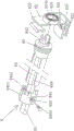
Fig. 2 is a detailed structure diagram of the external magnetic column driving transmission mechanism and the internal magnetic column driven transmission mechanism shown in fig. 1.
Fig. 3 is a detailed structural view of the active magnetic pillar device shown in fig. 2.
Fig. 4 is an exploded perspective view of the internal torque multiplier mechanism shown in fig. 1 and 2.
FIG. 5 is a schematic view of the blind lifting and shade turning actuator shown in FIG. 1.
Fig. 6 is a detailed structural view of the blind lifting and lowering and flap turning actuator shown in fig. 5.
Detailed Description
In order to make the technical essence and advantages of the present invention more clear, the applicant below describes in detail the embodiments, but the description of the embodiments is not a limitation of the present invention, and any equivalent changes made according to the inventive concept, which are only formal and not essential, should be considered as the technical scope of the present invention.
In the following description, all the concepts related to the directions or orientations of up, down, left, right, front and rear are based on the position state of fig. 1 and 2, and thus, they should not be construed as particularly limiting the technical solution provided by the present invention.
Referring to fig. 1 and 2, there is shown a window 6, the window 6 includes an inner frame 61, an inner glass 62 and an outer glass 63, the inner glass 62 and the outer glass 63 are respectively disposed at front and rear sides of the inner frame 61 in a facing state, peripheral edge portions of the inner glass 62 and the outer glass 63 protrude out of a side surface of the inner frame 61 facing outward to form a strip cavity, the strip cavity adheres the peripheral edge portions of the facing sides of the inner glass 62 and the outer glass 63 together with the side surface of the inner frame 61 facing outward in the strip cavity, a louver cavity 64 is formed between the inner glass 62 and the outer glass 63 and corresponding to a hollow region enclosed by the inner frame 61, the inner frame 61 has an upper cross frame 611, the upper cross frame 611 is disposed at a top of the louver cavity 64, an upper cross 6111 having a cavity opening facing the inner glass 62 is formed in a length direction of the upper cross frame 611, since the structure and function of the aforementioned window 6 are well known in the art, the applicant will not be further described below; a blind lifting and turning actuator 8 and a blind 10 are shown, the blind lifting and turning actuator 8 is disposed in the above-mentioned horizontal frame bar cavity 6111, the blind 10 is disposed in the above-mentioned blind cavity 64, and the blind lifting traction rope 101 and the blind turning rope 102 of the blind 10 are led into the upper horizontal frame bar cavity 6111 to be connected with the blind lifting and turning actuator 8.
As the technical scheme provided by the utility model: the self-powered electric magnetic driven hollow glass built-in shutter structure system also comprises an external magnetic column driving transmission mechanism 1, a built-in magnetic column driven transmission mechanism 2, an external driving motor 3, a built-in torque increasing mechanism 4, a hanging frame 5, a remote control operation mechanism 7 and an automatic power supply mechanism 20, wherein the external magnetic column driving transmission mechanism 1 is arranged at one side of the inner glass 62 opposite to the outer glass 63, the external magnetic column driving transmission mechanism 1 corresponds to the built-in magnetic column driven transmission mechanism 2 arranged in the upper transverse frame strip cavity 6111 and is mutually magnetically attracted by the inner glass 62, the external driving motor 3 is connected with the external magnetic column driving transmission mechanism 1, the built-in torque increasing mechanism 4 is arranged in the upper transverse frame strip cavity 6111 and is connected with the built-in magnetic column driven transmission mechanism 2, the hanging frame 5 is matched with the external magnetic column driving transmission mechanism 1 and is hung on the inner glass 62; the remote control operating mechanism 7 comprises a signal receiver 71 and a signal transmitter 72, the signal receiver 71 is preferably arranged on the inner glass 62 in a cementing manner and is electrically connected with the external driving motor 3, the signal transmitter 72 is wirelessly connected with the signal receiver 71 and is arranged along with the window 6, such as on a windowsill beside the window 6, or on a fixed seat fixed with a wall body for inserting the signal transmitter 72, and the like, the autonomous power supply mechanism 20 is arranged on the upper part of one side of the outer glass 63 opposite to the inner glass 62 and is electrically connected with the signal receiver 71, and the blind lifting and blind overturning actuating mechanism 8 is connected with the built-in torque increasing mechanism 4.
From the illustration of fig. 1 it can be determined that: in the present embodiment, as a preferable mode, the external magnetic column driving transmission mechanism 1 is installed on the side facing the building interior at the upper right corner of the inner glass 62 by hanging the rack 5 and preferably additionally adhering an adhesive, and the internal magnetic column driven transmission mechanism 2 is installed between the upper right corners of the inner and outer glasses 62 and 63, that is, at the right end of the upper horizontal frame cavity 6111, however, the applicant should explain that: relative to the setting position shown in fig. 1, if the external magnetic pillar driving transmission mechanism 1 is transferred to the upper left corner of the inner glass 62, and simultaneously the internal magnetic pillar driven transmission mechanism 2 is transferred to the left end of the upper horizontal frame bar cavity 6111, and the internal torque increasing mechanism 4 is transferred to the right end of the internal magnetic pillar driven transmission mechanism 2 and is set in the upper horizontal frame bar cavity 6111, and the self-powered mechanism 20 is transferred to the upper right corner of the rear glass 63, then it should be regarded as an equivalent technical means and still belong to the technical scope of the present invention.
Referring to fig. 2 in conjunction with fig. 1, the external magnetic pole active transmission mechanism 1 includes an external front housing 11, an external rear housing 12, an active magnetic pole device 13, an upper housing connecting plate 14, a lower housing connecting plate 15 and an external shield 16, the active magnetic pole device 13 is rotatably disposed between the external front housing 11 and the external rear housing 12, the upper portions of the front external case 11 and the rear external case 12 in the longitudinal direction are fitted to the upper case coupling plate 14 in the longitudinal direction facing downward, the lower parts of the external front casing 11 and the external rear casing 12 in the length direction are in inserting fit with the length direction of the upward side of the casing lower connecting plate 15, and the casing upper connecting plate 14 and the casing lower connecting plate 15, together with the external front casing 11, the external rear casing 12 and the active magnetic column device 13, are arranged in the outer shield cavity 161 of the outer shield 16 in an inserting fit manner; the driving magnetic column device 13 magnetically attracts the built-in magnetic column driven transmission mechanism 2 disposed in the upper cross frame bar cavity 6111 of the upper cross frame bar 611 through the inner glass 62, and the built-in torque amplification mechanism 4 is driven by the built-in magnetic column driven transmission mechanism 2 when the built-in magnetic column driven transmission mechanism 2 is driven to rotate; the external driving motor 3 is connected to the left end of the active magnetic column device 13, and the external driving motor 3 is disposed between the external front housing 11 and the left end of the external rear housing 12; the hanging rack 5 is matched with the rear side of the shell upper connecting plate 14 in the length direction; the signal receiver 71 of the remote control mechanism 7 is electrically connected to the external drive motor 3 at a position corresponding to the left end of the outer cover 16; the position of the blind lifting and curtain sheet overturning actuating mechanism 8 in the upper transverse frame bar cavity 6111 is located in the middle of the upper transverse frame bar cavity 6111 in the length direction, and the upper ends of the blind lifting traction ropes 101 and the curtain sheet overturning ladder ropes 102 of the blind 10 are guided into the upper transverse frame bar cavity 6111 from bottom to top through the cavity bottom wall of the upper transverse frame bar cavity 6111; the autonomous power supply mechanism 20 electrically connected to the signal receiver 71 is provided at the upper left corner of the side of the outer glass 63 facing away from the inner glass 62.
In the present embodiment, the front external housing 11 and the rear external housing 12 are preferably molded by using a plastic material.
As shown in fig. 2, front housing bosses 111 are formed at intervals in the upper portion and the lower portion in the longitudinal direction of the front external housing 11 on the side facing the rear external housing 12, a front housing upper insertion protrusion 112 is formed in the longitudinal direction of the upper side of the front external housing 11, and a front housing lower insertion protrusion 113 is formed in the longitudinal direction of the lower side of the front external housing 11; rear case tenons 121 are formed at positions corresponding to the front case mortise 111 at upper and lower longitudinal portions of the rear external case 12 facing the front external case 11, respectively, at intervals, the rear case tenons 121 being in mortise-and-tenon engagement with the front case mortise 111, a rear case upper insertion protrusion 122 being formed in a longitudinal direction of an upward facing side of the rear external case 12, and a rear case lower insertion protrusion 123 being formed in a longitudinal direction of a downward facing side of the rear external case 12; the front housing upper fitting projection 112 and the rear housing upper fitting projection 122 are fitted to each other and fitted to the downward side of the housing upper link plate 14, and the front housing lower fitting projection 113 and the rear housing lower fitting projection 123 are fitted to each other and fitted to the upward side of the housing lower link plate 15; the active magnetic pole device 13 is rotatably disposed in a cavity formed by the cooperation of the front shell magnetic pole cavity 114 formed at the right end of the front external shell 11 and the rear shell magnetic pole cavity 124 formed at the right end of the rear external shell 12; the external driving motor 3 is arranged in a cavity formed by matching a front shell motor cavity 116 formed at the left end of the external front shell 11 and a rear shell motor cavity 126 formed at the left end of the external rear shell 12; the rear side of the external rear shell 12 corresponds to the internal magnetic column driven transmission mechanism 2 which drives the internal torque increasing mechanism 4 to act through the internal glass 62; the cross section of the hanging rack 5 is in an inverted L shape; a positioner 9 is provided in the blind lifting/lowering/inverting actuator 8 for actuating the blind lifting/lowering rope 101 and the blind inverting rope 102 of the blind 10, a power source for operating the signal receiver 71 of the remote control unit 7 is supplied from the autonomous power supply unit 20, and the positioner 9 is electrically connected to the signal receiver 71 by a line.
Since the positioner 9 is disposed on the blind lifting and shade turning actuator 8 as an embodiment, the external driving motor 3 can be controlled by the positioner 9 via the signal receiver 71 via a circuit. The applicant does not describe the function of the positioner in detail, since it belongs to the prior art, for example, see CN111395932A (manual-automatic hollow glass built-in shutter).
Continuing to refer to fig. 2, an upper insertion projection engagement groove 141 is formed in the longitudinal direction of the downward side of the case upper coupling plate 14, and a lower insertion projection engagement groove 151 is formed in the longitudinal direction of the upward side of the case lower coupling plate 15, the front case upper insertion projection 112 and the rear case upper insertion projection 122 are engaged with the upper insertion projection engagement groove 141 in a state of being engaged with each other, and the front case lower insertion projection 113 and the rear case lower insertion projection 123 are engaged with the lower insertion projection engagement groove 151 in a state of being engaged with each other; the cross-sectional shape of the front housing upper-fitting protrusion 112 and the rear housing upper-fitting protrusion 122 after fitting each other is dovetail-shaped, the cross-sectional shape of the front housing lower-fitting protrusion 113 and the rear housing lower-fitting protrusion 123 after fitting each other is dovetail-shaped, and the cross-sectional shapes of the upper-fitting protrusion engaging groove 141 and the lower-fitting protrusion engaging groove 151 are likewise dovetail-shaped.
The applicant needs to state that: the dovetail shape mentioned above is only a preferred example and does not imply that this shape is necessary.
Continuing to refer to fig. 2, a housing upper connecting plate positioning clip strip 142 protruding from the upper surface of the housing upper connecting plate 14 is formed in the length direction of the upward side of the housing upper connecting plate 14, a housing lower connecting plate positioning clip strip 152 protruding from the lower surface of the housing lower connecting plate 15 is formed in the length direction of the downward side of the housing lower connecting plate 15, a housing upper connecting plate positioning clip strip groove 1611 is formed in the top wall of the outer shield cavity 161 of the outer shield 16 along the length direction of the top wall, a housing lower connecting plate positioning clip strip groove 1612 is formed in the bottom wall of the outer shield cavity 161 along the length direction of the bottom wall, the housing upper connecting plate positioning clip strip 142 is engaged with the housing upper connecting plate positioning clip strip groove 1611, and the housing lower connecting plate positioning clip strip 152 is engaged with the housing lower connecting plate positioning clip strip groove 1612; a hanging rack insertion groove 143 is formed on the rear side of the housing upper connecting plate 14 in the longitudinal direction, a hanging rack protrusion 51 is formed on the lower portion of the hanging rack 5 along the longitudinal direction of the hanging rack 5, the hanging rack protrusion 51 is fitted into the hanging rack insertion groove 143, the upper portion of the hanging rack 5 is hooked on the inner glass 62 (shown in fig. 1), and the cross-sectional shape of the hanging rack 5 is L-shaped as shown in fig. 1 and 2.
Continuing to refer to fig. 2, a front housing right support bearing cavity 1141 is formed at a right end portion of the front housing magnetic pillar cavity 114 of the front external housing 11, and a rear housing right support bearing cavity 1241 is formed at a right end portion of the rear housing magnetic pillar cavity 124 of the rear external housing 12, the front housing right support bearing cavity 1141 and the rear housing right support bearing cavity 1241 corresponding to each other; a front housing left support bearing cavity 1142 is formed at the left end of the front housing magnetic stud cavity 114 of the front exterior housing 11, and a rear housing left support bearing cavity 1242 is formed at the left end of the rear housing magnetic stud cavity 124 of the rear exterior housing 12, the front housing left support bearing cavity 1142 and the rear housing left support bearing cavity 1242 corresponding to each other; a front casing motor lead-wire abdicating cavity 117 is formed at the rear side of the left end surface of the external front casing 11, a rear casing motor lead-wire abdicating cavity 127 is formed at the front side of the left end surface of the external rear casing 12 and at the position corresponding to the front casing motor lead-wire abdicating cavity 117, the front casing motor lead-wire abdicating cavity 117 and the rear casing motor lead-wire abdicating cavity 127 are matched together to form a motor power lead-in hole; the external driving motor 3 arranged in the cavity formed by the cooperation of the front shell motor cavity 116 and the rear shell motor cavity 126 is electrically connected with the signal receiver 71 through a motor power line 31; a sheath motor power line abdicating cavity 162 is formed at the left end of the sheath 16 and at a position corresponding to the motor power line inlet; the built-in magnetic column driven transmission mechanism 2 comprises a driven magnetic column device mounting rack 21 and a driven magnetic column device 22, the driven magnetic column device mounting rack 21 is arranged in the hollow glass built-in shutter at a position corresponding to the external rear shell 12, the driven magnetic column device 22 is arranged on the driven magnetic column device mounting rack 21, the built-in torque increasing mechanism 4 is arranged between the right end of the shutter lifting and shutter turning executing mechanism 8 and the left end of the driven magnetic column device 22 and is connected with the driven magnetic column device 22, and the built-in torque increasing mechanism 4 drives the shutter lifting and shutter turning executing mechanism 8 to enable the shutter lifting and shutter turning executing mechanism 8 to drive the shutter lifting traction rope 101 and the shutter turning rope 102 of the shutter 10; the positioner 9 is positioned in the middle of the shutter lifting and shutter turning actuating mechanism 8; a turnover shaft supporting seat inserting groove 61112 is formed in the bottom wall of the upper transverse bar cavity 6111 of the upper transverse frame bar 611, and the blind lifting and curtain piece turnover actuating mechanism 8 is fixedly inserted into the turnover shaft supporting seat inserting groove 61112; the autonomous power supply mechanism 20 includes a solar photovoltaic power generation device 201 and a hanging plate 202, the solar photovoltaic power generation device 201 faces away from one side of the outer glass 63, the hanging plate 202 and the solar photovoltaic power generation device 201 are hung at the upper left corner of one side of the outer glass 63 facing away from the inner glass 62, and the solar photovoltaic power generation device 201 is electrically connected with the signal receiver 71 through a conducting wire.
Referring to fig. 3 in conjunction with fig. 2, the structure of the driven magnetic pillar device 22 disposed on the driven magnetic pillar device mounting bracket 21 is the same as that of the driving magnetic pillar device 13; the built-in torque amplification mechanism 4 is connected with the driven magnetic column device 22 at a position corresponding to the left end of the driven magnetic column device mounting frame 21; the external driving motor 3 is a motor with a forward and reverse rotation function, and an external driving motor shaft 32 of the external driving motor 3 faces to the right and is connected with the driving magnetic column device 13; the active magnetic column device 13 comprises a magnetic column sleeve 131, a left magnetic column 132, a right magnetic column 133, a left magnetic column limiting seat 134, a right magnetic column limiting seat 135 and a magnetic column non-magnetic separation disc 136, the magnetic column sleeve 131 is made of magnetic conductive material and the magnetic column sleeve 131 is arranged in a cavity formed by the cooperation of the front housing magnetic column cavity 114 and the rear housing magnetic column cavity 124, a magnetic column sleeve groove 1312 for communicating the magnetic column sleeve cavity 1311 of the magnetic column sleeve 131 with the outside is formed in the length direction of one side of the magnetic column sleeve 131, a magnetic column positioning flange 1313 recessed towards the magnetic column sleeve cavity 1311 is formed in the length direction of the other side of the magnetic column sleeve 131, the left magnetic column 132, the magnetic column non-magnetic separation disc 136 and the right magnetic column 133 are sequentially arranged in the magnetic column sleeve cavity 1311 from left to right, and a left magnetic column positioning flange fitting groove 1321 is formed on the left magnetic column 132 along the length direction of the left magnetic column 132, a right column positioning flange matching groove 1331 is also formed on the right magnetic column 133 along the length direction of the right magnetic column 133, a left column positioning flange matching groove 1321 and a right column positioning flange matching groove 1331 correspond to and match the magnetic column positioning flange 1313, the right end of the left column limiting seat 134 is inserted and fixed with the left opening of the magnetic column sleeve cavity 1311 at a position corresponding to the left end of the left magnetic column 132, the left end of the left column limiting seat 134 protrudes out of the left end face of the magnetic column sleeve 131 and is formed with a left supporting bearing seat 1341, a left supporting bearing 13411 is arranged on the left supporting bearing 1341, a left column limiting seat protruding strip 1342 is formed on the left column limiting seat 134 and at a position corresponding to the magnetic column sleeve tensioning groove 1312, the left end of the right column limiting seat 135 is fixedly inserted and fixed with the right opening of the magnetic column sleeve cavity 1311 at a position corresponding to the right end of the right magnetic column 133, the right end of the right pillar retainer 135 protrudes out of the right end surface of the pillar sleeve 131 and forms a right supporting bearing seat 1351, a right supporting bearing 13511 is disposed on the right supporting bearing seat 1351, a right pillar retainer protrusion 1353 is disposed on the right pillar retainer 135 and at a position corresponding to the pillar sleeve tensioning groove 1312, and the left pillar retainer protrusion 1342 and the right pillar retainer protrusion 1353 are engaged with the pillar sleeve tensioning groove 1312; the left support bearing 13411 is supported in a bearing chamber formed by the front housing left support bearing chamber 1142 and the rear housing left support bearing chamber 1242 being engaged with each other, and the right support bearing 13511 is supported in a bearing chamber formed by the front housing right support bearing chamber 1141 and the rear housing right support bearing chamber 1241 being engaged with each other; an external driving motor shaft 32 of the external driving motor 3 is connected with the left supporting bearing seat 1341 or the right supporting bearing seat 1351; an upper horizontal frame strip cavity sealing sheet 61111 is arranged in the length direction corresponding to one side of the upper horizontal frame strip cavity 6111 facing the inner glass 62 and used for shielding the built-in torque increasing mechanism 4, the blind lifting traction rope 101 for driving the blind 10 and the blind lifting and blind overturning actuating mechanism 8 of the blind overturning ladder rope 102 and the positioner 9.
Continuing with FIG. 3, a left support bearing housing motor shaft connection aperture 13412 is formed at an axially central location on said left support bearing housing 1341 and a right support bearing housing motor shaft connection aperture 13512 is formed at an axially central location on said right support bearing housing 1351, the non-rotating bearing cup of said left support bearing 13411 being positioned within the bearing cavity formed by the cooperation of said front housing left support bearing cavity 1142 and said rear housing left support bearing cavity 1242, the non-rotating bearing cup of said right support bearing 13511 being positioned within the bearing cavity formed by the cooperation of said front housing right support bearing cavity 1141 and said rear housing right support bearing cavity 1241; the external driving motor shaft 32 of the external driving motor 3 is inserted into the left supporting bearing block motor shaft connecting hole 13412 to be connected with the left supporting bearing block 1341 or inserted into the right supporting bearing block motor shaft connecting hole 13512 to be connected with the right supporting bearing block 1351; a left magnetic pillar stopper fitting groove corresponding to and fitting with the position of the magnetic pillar positioning flange 1313 is formed at the right end of the left magnetic pillar stopper 134, and a right magnetic pillar stopper fitting groove 1352 corresponding to and fitting with the position of the magnetic pillar positioning flange 1313 is formed at the left end of the right magnetic pillar stopper 135; the angle of deflection of the magnetic pole direction of the left magnetic pole 132 and the right magnetic pole 133 is different from the angle of deflection of the magnetic pole direction of the driven magnetic pole device 22.
If the active magnetic cylinder assembly 13 shown in fig. 2 is rotated 180, the external drive motor shaft 32 is inserted into the right support bearing housing motor shaft connection hole 13512 to connect to the right support bearing housing 1351.
As shown in fig. 2, a magnetic opening 212 communicating with the cavity 211 of the driven magnetic column device mounting bracket is formed in the length direction of the driven magnetic column device mounting bracket 21 toward the external rear housing 12, a mounting bracket offset hole 213 is formed at the left end of the driven magnetic column device mounting bracket 21, and a window upper cross frame strip fixing leg 214 for cooperating with the upper cross frame strip 611 shown in fig. 5 is formed on the upper surface of the driven magnetic column device mounting bracket 21 and at the left and right ends thereof.
Referring to fig. 4 in conjunction with fig. 1 and 2, the built-in torque amplifying mechanism 4 corresponds to the left side of the mount recess 213, the built-in torque amplifying mechanism 4 includes a gear case 41, a gear case cover 42, a main gear 43, a first transition gear i 44, a second transition gear ii 45 and a driven gear 46, a first bearing cavity i 411 of the gear case is formed on the left wall of the gear case 41, a second bearing cavity ii 412 of the gear case is formed on the right wall of the gear case 41, the gear case cover 42 is fitted to the front side of the gear case 41, the main gear 43 is formed on the main gear shaft 431 and is located in the gear case cavity 413 of the gear case 41, the right end of the main gear shaft 431 is inserted and connected to the left end of the driven magnetic column device 22 at a position corresponding to the mount recess 213, the first transition gear i 44 and the second transition gear ii 45 are coaxially formed on the transition gear shaft 47, and the first transition gear i 44 is engaged with the aforementioned main gear 43, the second transition gear ii 45 is positioned to the left of the first transition gear i 44 and engaged with the driven gear 46, the center position of the right end of the driven gear 46 is fitted over the left end of the aforementioned main gear shaft 431, and a driven gear shaft head 461 is formed at the center position of the left end of the driven gear 46, a reverse shaft coupling hole 462 is formed at the axial center position of the driven gear shaft head 461, a left bearing 463 is further fitted over the driven gear shaft head 461, the left bearing 463 is supported in the aforementioned gear case first support bearing chamber i 411, a right bearing 4311 is provided on the aforementioned main gear shaft 431 and positioned to the right of the main gear 43, the right bearing 4311 is supported in the aforementioned gear case second support bearing chamber ii 412, the left end and the right end of the aforementioned transition gear shaft 47 are respectively rotatably supported in the transition gear shaft pivotal mounting holes 48 provided in the left and right chamber walls of the gear case chamber 413, the shutter lifting and flap turning actuator 8 is connected to the turning shaft connecting hole 462.
Also shown in fig. 4 are gearbox cover snap-fit cavities 414 above and below the cavity walls of the left and right side walls of the aforementioned gearbox 4, namely the gearbox housing cavity 413, while gearbox cover snap-fit feet 421 extend on the gearbox cover 42 and at positions corresponding to the gearbox cover snap-fit cavities 414, the gearbox cover snap-fit feet 421 snap-fit with the gearbox cover snap-fit cavities 414, so that the gearbox cover 42 securely fits with the gearbox 41.
Referring to fig. 5 and 6 and continuing to combine with fig. 1, the actuating mechanism 8 for lifting and turning blind slats includes a turning shaft 81, a pair of turning shaft supporting seats 82, a pair of turning rope wheels 83 and a pair of rope rolling devices 84, the pair of turning shaft supporting seats 82 are disposed in the upper cross frame bar cavity 6111 of the upper cross frame bar 611 and are fixedly inserted into the turning shaft supporting seat insertion slot 61112 formed in the bottom wall of the upper cross frame bar cavity 6111, the pair of rope rolling devices 84 are respectively sleeved on the two ends of the turning shaft 81 in a state of being suspended on the top wall and the bottom wall of the upper cross frame bar cavity 6111, the pair of rope rolling devices 84 are respectively and rotatably supported on the pair of turning shaft supporting seats 82 towards one end of the pair of turning shaft supporting seats 82, the right end of the turning shaft 81 passes through the right rope rolling device of the pair of rope rolling devices 84 and is then inserted into the turning shaft connecting hole 462, the left end of the turning shaft 81 sequentially passes through the right positioner 9 and the left rope rolling device 84 from left One rope winder on the side is rotatably supported on the left turnover shaft supporting seat in the pair of turnover shaft supporting seats 82, and the pair of turnover rope wheels 83 are respectively and directly formed on the pair of rope winders 84 at the positions corresponding to the pair of turnover shaft supporting seats 82; the blind lifting/lowering rope 101 and the slat overturning rope 102 of the blind 10 are paired, the upper ends of the pair of blind lifting/lowering ropes 101 are respectively led to the pair of rope winders 84 and spirally wound around the pair of rope winders 84, and then fixed to the ends of the pair of rope winders 84 away from the pair of overturning shaft supporting seats 82, and the upper ends of the pair of slat overturning ropes 102 are led to the pair of overturning sheaves 83 and wound around the overturning sheaves 83 for one to two turns.
Continuing to refer to fig. 5 and 6, a trip shaft support nest 821 is formed in the lower portion of each of the pair of trip shaft supports 82, the inserting groove 821 of the turning shaft supporting seat is inserted into the inserting groove 61112 of the upper cross frame strip cavity 6111 (i.e. "inserting and fixing"), and a support seat traction rope abdicating hole 822 is arranged at the central position of the lower parts of the pair of turnover shaft support seats 82, a turning sheave chamber 823 is formed in the upper part of each of the pair of turning shaft support bases 82, the pair of turning sheaves 83 are formed directly in the pair of rope winders 84 at positions corresponding to the turning sheave chambers 823, and a bearing 824 is provided in each of the pair of turning shaft support bases 82, a rope winder rotation support 843 extends from each of the pair of rope winders 84 toward one end of the pair of spool support 82, the rope winder rotation support 843 is in rotation fit with a bearing hole 8241 of the bearing 824; the upper ends of the pair of blind lifting traction ropes 101 penetrate through the supporting seat traction rope abdicating holes 822 from bottom to top, and the upper ends of the pair of blind turnover rope ropes 102 are guided upwards to the turnover rope pulley cavities 823 at positions corresponding to the turnover rope grooves 825 formed in the front and rear sides of the pair of turnover shaft supporting seats 82 and then sleeved on the pair of turnover rope pulleys 83; one end of each of the pair of rope winders 84, which is far away from the pair of turning shaft supporting seats 82, is provided with a lifting traction rope clamping seat 841, the lifting traction rope clamping seat 841 is provided with a blind lifting traction rope clamping groove 8411, the lifting traction rope clamping seat 841 is also provided with a clamping seat locking hole 842, a clamping seat locking screw 8421 is arranged at a position corresponding to the clamping seat locking hole 842, the upper end parts of the pair of blind lifting traction ropes 101 are clamped in the blind lifting traction rope clamping groove 8411, and the clamping seat locking screw 8421 is locked with the turning shaft 81; claw grooves 844 are formed on the outer walls of the pair of rope reels 84 at intervals in the circumferential direction around the pair of rope reels 84, claws 8412 corresponding to the claw grooves 844 are formed on the elevating traction rope holder 841 at intervals in the circumferential direction around the elevating traction rope holder 841, and the claws 8412 are engaged with the claw grooves 844; the positioner 9 is embedded in the upper cross frame strip cavity 6111.
When the blind of the venetian blind 10 is to be turned over, the signal transmitter 72 is operated by the operator, the signal transmitter 72 transmits a signal to the signal receiver 71, the external driving motor 3 is operated by the signal receiver 71, the external driving motor shaft 32 of the external driving motor 3 drives the left supporting bearing 1341, since the right end of the left magnetic pillar defining seat 134 is inserted into the magnetic pillar sleeve 131 and the left magnetic pillar defining seat protruding strip 1342 thereof is engaged with the magnetic pillar sleeve 131 at a position corresponding to the magnetic pillar sleeve tensioning groove 1312, and the right end of the left magnetic pillar defining seat 134 is engaged with the magnetic pillar positioning flange 1313 of the magnetic pillar sleeve 131 by the left magnetic pillar defining seat engaging groove, the entire driving magnetic pillar means 13 is rotated by the external driving motor shaft 32 driving the left magnetic pillar defining seat 134 and the driven magnetic pillar means 22 of the built-in magnetic pillar driven transmission mechanism 2 is driven by the left end of the driven magnetic pillar means 22 through the main gear 43, a first transition gear I44 is driven by a main gear 43, and a driven gear 46 is driven by a second transition gear II 45 via a transition gear shaft 47. Since the right end of the turning shaft 81 is connected (inserted and embedded) to the turning shaft connection hole 462 of the driven gear 46, the driven gear 46 drives the turning shaft 81 to rotate through an angle, and the turning shaft 81 drives the shutter lifting and turning member of the shutter turning actuator 8, such as the turning rope pulley 83; if the blind 10 is to be raised, the blind lifting/lowering cord 101 is wound around the cord winder 84 of the structural system of the blind lifting/lowering and slat-inverting actuator 8, similarly as described above. The slats of the blind 10 are flipped inward or outward (also referred to as "flipped downward or upward") and the blind 10 is raised or lowered depending on the mode of operation of the signal emitter 72 by the operator.
In the above process, if the blind 10 is lifted up or lowered down to the limit extent, but the operator's finger is still not away from the upward touching arrow or the downward touching arrow on the signal transmitter 72, the external driving motor 3 is stopped by the positioner 9, i.e. the positioner 9 cuts off the working power of the external driving motor 3 through the signal receiver 71, because the positioner 9 functions to control the number of the forward and reverse rotation turns of the external driving motor 3 to achieve the purpose of accurately controlling the blind 10 to ascend or descend to the limit position, so as to control the external driving motor 3 and protect the external driving motor 3.
Preferably, the cross-sectional shape of the reversing shaft 81 is a regular hexagon, and the left bearing housing motor shaft connection hole 13412, the right bearing housing motor shaft connection hole 13512, the master gear shaft 431, and the left end hole of the driven magnetic column device 22 are all regular hexagons.
To sum up, the technical solution provided by the present invention remedies the defects in the prior art, successfully completes the invention task, and faithfully embodies the technical effects mentioned in the above technical effect column by the applicant.
Claims (10)
1. A self-powered electromagnetic driven hollow glass built-in shutter comprises a window body (6), wherein the window body (6) comprises an inner frame body (61), inner glass (62) and outer glass (63), the inner glass (62) and the outer glass (63) are respectively arranged on the front side and the rear side of the inner frame body (61) in a face-to-face state, the peripheral edge parts of the inner glass (62) and the outer glass (63) extend out of one side surface of the inner frame body (61) facing outwards to form a rubber strip cavity, the peripheral edge parts of one opposite side of the inner glass (62) and the outer glass (63) and one side surface of the periphery of the inner frame body (61) facing outwards are adhered together by rubber strips in the rubber strip cavity, a blind cavity (64) is formed between the inner glass (62) and the outer glass (63) and corresponds to a hollow area enclosed by the inner frame body (61), the inner frame body (61) is provided with an upper cross frame strip (611), the upper transverse frame strip (611) is positioned at the top of the blind cavity (64), and an upper transverse frame strip cavity (6111) with a cavity opening facing the inner glass (62) is formed in the length direction of the upper transverse frame strip (611); the blind lifting and curtain sheet overturning actuating mechanism (8) and the blind (10) are arranged, the blind lifting and curtain sheet overturning actuating mechanism (8) is arranged in the upper transverse frame bar cavity (6111), the blind (10) is arranged in the blind cavity (64), and a blind lifting traction rope (101) and a blind sheet overturning ladder rope (102) of the blind (10) are introduced into the upper transverse frame bar cavity (6111) and connected with the blind lifting and curtain sheet overturning actuating mechanism (8); the method is characterized in that: the device also comprises an external magnetic column driving transmission mechanism (1), an internal magnetic column driven transmission mechanism (2), an external driving motor (3), an internal torque increasing mechanism (4), a hanging frame (5), a remote control operation mechanism (7) and an automatic power supply mechanism (20), wherein the external magnetic column driving transmission mechanism (1) is arranged on one side of the inner glass (62) opposite to the outer glass (63), the external magnetic column driving transmission mechanism (1) corresponds to the internal magnetic column driven transmission mechanism (2) arranged in the upper transverse frame strip cavity (6111) and is mutually magnetically attracted by the inner glass (62), the external driving motor (3) is connected with the external magnetic column driving transmission mechanism (1), the internal torque increasing mechanism (4) is arranged in the upper transverse frame strip cavity (6111) and is connected with the internal magnetic column driven transmission mechanism (2), the hanging frame (5) is matched with the external magnetic column driving transmission mechanism (1), the remote control operation mechanism (7) comprises a signal receiver (71) and a signal transmitter (72), the signal receiver (71) is arranged on the inner glass (62) and is electrically connected with the external driving motor (3), the signal transmitter (72) is wirelessly connected with the signal receiver (71) and is arranged along with the window body (6), the autonomous power supply mechanism (20) is arranged at the upper part of one side of the outer glass (63) back to the inner glass (62) and is electrically connected with the signal receiver (71), and the shutter lifting and shutter turning actuating mechanism (8) is connected with the built-in torque increasing mechanism (4).
2. The self-powered electrically-driven magnetically-actuated venetian blind as claimed in claim 1, wherein the external magnetic pole driving transmission mechanism (1) comprises an external front housing (11), an external rear housing (12), a driving magnetic pole unit (13), an upper housing coupling plate (14), a lower housing coupling plate (15) and an outer shield (16), the driving magnetic pole unit (13) is rotatably disposed between the external front housing (11) and the external rear housing (12), and the upper portions of the external front housing (11) and the external rear housing (12) in the longitudinal direction are in insertion-fit with the longitudinal direction of the side of the upper housing coupling plate (14) facing downward, and the lower portions of the external front housing (11) and the external rear housing (12) in the longitudinal direction are in insertion-fit with the side of the lower housing coupling plate (15) facing upward, the upper shell connecting plate (14) and the lower shell connecting plate (15) are arranged in an outer shield cavity (161) of an outer shield (16) in an inserting manner together with the external front shell (11), the external rear shell (12) and the active magnetic column device (13); the driving magnetic column device (13) is separated from the inner glass (62) and the built-in magnetic column driven transmission mechanism (2) arranged in the upper transverse frame bar cavity (6111) of the upper transverse frame bar (611) to be mutually magnetically attracted, and the built-in torque increasing mechanism (4) is driven by the built-in magnetic column driven transmission mechanism (2) when the built-in magnetic column driven transmission mechanism (2) is driven to rotate; the external driving motor (3) is connected with the left end of the active magnetic column device (13), and the external driving motor (3) is arranged between the left ends of the external front shell (11) and the external rear shell (12); the hanging frame (5) is matched with the rear side of the shell upper connecting plate (14) in the length direction; the signal receiver (71) of the remote control operation mechanism (7) is electrically connected with the external driving motor (3) at a position corresponding to the left end of the outer shield (16); the position of the blind lifting and curtain sheet overturning actuating mechanism (8) in the upper transverse frame cavity (6111) is positioned in the middle of the length direction of the upper transverse frame cavity (6111), and the upper ends of a blind lifting traction rope (101) and a curtain sheet overturning ladder rope (102) of the blind (10) pass through the cavity bottom wall of the upper transverse frame cavity (6111) and are led into the upper transverse frame cavity (6111) from bottom to top; the autonomous power supply mechanism (20) electrically connected to the signal receiver (71) is disposed at the upper left corner of the side of the outer glass (63) facing away from the inner glass (62).
3. The self-powered electrically and magnetically driven hollow glass built-in blind according to claim 2, wherein the front housing-in mortise (111) is formed at an upper portion of the front housing-outside (11) facing the rear housing-outside (12) in the longitudinal direction and at a lower portion thereof in the longitudinal direction at intervals, and a front housing-in insertion projection (112) is formed at a side of the front housing-outside (11) facing upward in the longitudinal direction and a front housing-in insertion projection (113) is formed at a side of the front housing-outside (11) facing downward in the longitudinal direction; rear case tenons (121) are formed at the upper part and the lower part of the length direction of the side of the external rear case (12) facing the external front case (11) and at the positions corresponding to the front case mortise (111) respectively in an interval state, the rear case tenons (121) are in mortise-tenon joint fit with the front case mortise (111), a rear case upper inserting convex strip (122) is formed at the length direction of the side of the external rear case (12) facing upwards, and a rear case lower inserting convex strip (123) is formed at the length direction of the side of the external rear case (12) facing downwards; the front housing upper insert-fit convex line (112) and the rear housing upper insert-fit convex line (122) are fitted with each other and with one side of the housing upper coupling plate (14) facing downward, and the front housing lower insert-fit convex line (113) and the rear housing lower insert-fit convex line (123) are fitted with each other and with one side of the housing lower coupling plate (15) facing upward; the active magnetic column device (13) is rotationally arranged in a cavity formed by matching a front shell magnetic column cavity (114) formed at the right end of the external front shell (11) with a rear shell magnetic column cavity (124) formed at the right end of the external rear shell (12); the external driving motor (3) is arranged in a cavity formed by matching a front shell motor cavity (116) formed at the left end of the external front shell (11) with a rear shell motor cavity (126) formed at the left end of the external rear shell (12); the rear side of the external rear shell (12) corresponds to the built-in magnetic column driven transmission mechanism (2) which drives the built-in torque increasing mechanism (4) to act through the inner glass (62); the cross section of the hanging rack (5) is in an inverted L shape; a positioner (9) is arranged on the blind lifting and turning actuating mechanism (8) for driving a blind lifting traction rope (101) and a blind turning rope (102) of the blind (10) to act, a power supply for supporting the work of a signal receiver (71) of the remote control operating mechanism (7) is provided by the self-powered mechanism (20), and the positioner (9) is electrically connected with the signal receiver (71) by a line.
4. A self-powered electrically and magnetically driven hollow glass built-in blind as claimed in claim 3, wherein an upper insertion projection engaging groove (141) is formed in a longitudinal direction of a downward facing side of said housing upper coupling plate (14), and a lower insertion projection engaging groove (151) is formed in a longitudinal direction of an upward facing side of said housing lower coupling plate (15), said front housing upper insertion projection (112) and said rear housing upper insertion projection (122) are in insertion engagement with said upper insertion projection engaging groove (141) in a state of engagement with each other, and said front housing lower insertion projection (113) and said rear housing lower insertion projection (123) are in insertion engagement with said lower insertion projection engaging groove (151) in a state of engagement with each other; the cross section of the front shell upper inserting and embedding convex strip (112) and the rear shell upper inserting and embedding convex strip (122) matched with each other is in a dovetail shape, the cross section of the front shell lower inserting and embedding convex strip (113) and the rear shell lower inserting and embedding convex strip (123) matched with each other is in a dovetail shape, and the cross sections of the upper inserting and embedding convex strip matching groove (141) and the lower inserting and embedding convex strip matching groove (151) are also in a dovetail shape; a positioning clamping strip (142) of the upper connecting plate of the shell, which is protruded on the upper surface of the upper connecting plate (14) of the shell, is formed in the length direction of the upward side of the upper connecting plate (14) of the shell, a positioning clamping strip (152) of the lower shell connecting plate protruding from the lower surface of the lower shell connecting plate (15) is formed in the length direction of the downward side of the lower shell connecting plate (15), a shell upper connecting plate positioning clamping strip groove (1611) is formed on the top wall of the outer shield cavity (161) of the outer shield (16) along the length direction of the top wall, a positioning clamping strip groove (1612) of the shell lower connecting plate is formed on the bottom wall of the outer shield cavity (161) along the length direction of the bottom wall, the shell upper connecting plate positioning clamping strip (142) is clamped and matched with the shell upper connecting plate positioning clamping strip groove (1611), the shell lower connecting plate positioning clamping strip (152) is clamped and matched with the shell lower connecting plate positioning clamping strip groove (1612); a hanging rack insertion groove (143) is formed on the rear side of the shell upper connecting plate (14) in the length direction, a hanging rack convex strip (51) is formed on the lower portion of the hanging rack (5) along the length direction of the hanging rack (5), and the hanging rack convex strip (51) is inserted and matched with the hanging rack insertion groove (143).
5. A self-powered electrically-powered magnetically-actuated hollow glass internal louver according to claim 3, wherein a front housing right support bearing cavity (1141) is formed at a right end portion of the front housing magnetic cylinder cavity (114) of said external front housing (11), and a rear housing right support bearing cavity (1241) is formed at a right end portion of the rear housing magnetic cylinder cavity (124) of said external rear housing (12), the front housing right support bearing cavity (1141) and the rear housing right support bearing cavity (1241) corresponding to each other; a front housing left support bearing cavity (1142) is formed at the left end of the front housing magnetic pole cavity (114) of the external front housing (11), a rear housing left support bearing cavity (1242) is formed at the left end of the rear housing magnetic pole cavity (124) of the external rear housing (12), and the front housing left support bearing cavity (1142) and the rear housing left support bearing cavity (1242) correspond to each other; a front shell motor lead yielding cavity (117) is formed on the rear side of the left end face of the external front shell (11), a rear shell motor lead yielding cavity (127) is formed on the front side of the left end face of the external rear shell (12) and at a position corresponding to the front shell motor lead yielding cavity (117), and the front shell motor lead yielding cavity (117) and the rear shell motor lead yielding cavity (127) are matched together to form a motor power lead inlet; the external driving motor (3) arranged in a cavity formed by the cooperation of the front shell motor cavity (116) and the rear shell motor cavity (126) is electrically connected with the signal receiver (71) through a motor power line (31); a protective cover motor power line abdicating cavity (162) is arranged at the left end of the protective cover (16) and at the position corresponding to the motor power line lead-in hole; the built-in magnetic column driven transmission mechanism (2) comprises a driven magnetic column device mounting rack (21) and a driven magnetic column device (22), the driven magnetic column device mounting rack (21) is arranged in the hollow glass built-in shutter at a position corresponding to the external rear shell (12), the driven magnetic column device (22) is arranged on the driven magnetic column device mounting rack (21), the built-in torque increasing mechanism (4) is arranged between the right end of the blind lifting and curtain sheet overturning executing mechanism (8) and the left end of the driven magnetic column device (22) and is connected with the driven magnetic column device (22), and the built-in torque increasing mechanism (4) drives the blind lifting and curtain sheet overturning executing mechanism (8) to enable the blind lifting and curtain sheet overturning executing mechanism (8) to drive a blind lifting traction rope (101) and a blind sheet overturning ladder rope (102) of the blind (10); the positioner (9) is positioned in the middle of the blind lifting and curtain sheet overturning actuating mechanism (8); a turnover shaft supporting seat inserting and embedding groove (61112) is formed in the cavity bottom wall of an upper transverse bar cavity (6111) of the upper transverse frame bar (611), and the blind lifting and curtain piece turnover actuating mechanism (8) is fixedly inserted and embedded in the turnover shaft supporting seat inserting and embedding groove (61112); the automatic power supply mechanism (20) comprises a solar photovoltaic power generation device (201) and a hanging plate (202), the solar photovoltaic power generation device (201) faces away from one side of the outer glass (63), the hanging plate (202) and the solar photovoltaic power generation device (201) are hung on the upper left corner of one side, back to the inner glass (62), of the outer glass (63), and the solar photovoltaic power generation device (201) is electrically connected with the signal receiver (71) through a conducting wire.
6. A self-powered electrically-powered magnetically-actuated insulated glass internal blind according to claim 5, characterized in that the structure of said driven magnetic cylinder means (22) provided on said driven magnetic cylinder means mounting bracket (21) is identical to the structure of said driving magnetic cylinder means (13); the built-in torque increasing mechanism (4) is connected with the driven magnetic column device (22) at a position corresponding to the left end of the driven magnetic column device mounting frame (21); the external driving motor (3) has a positive and negative rotation function, and an external driving motor shaft (32) of the external driving motor (3) faces to the right and is connected with the driving magnetic column device (13); the active magnetic column device (13) comprises a magnetic column sleeve (131), a left magnetic column (132), a right magnetic column (133), a left magnetic column limiting seat (134), a right magnetic column limiting seat (135) and a magnetic column non-magnetic separation disc (136), the magnetic column sleeve (131) is made of magnetic conductive materials, the magnetic column sleeve (131) is arranged in a cavity formed by matching the front shell magnetic column cavity (114) and the rear shell magnetic column cavity (124), a magnetic column sleeve tensioning groove (1312) used for enabling the magnetic column sleeve cavity (1311) of the magnetic column sleeve (131) to be communicated with the outside is formed in the length direction of one side of the magnetic column sleeve (131), a magnetic column positioning flange (1313) sunken towards the direction of the magnetic column sleeve cavity (1311) is formed in the length direction of the other side of the magnetic column sleeve (131), the left magnetic column (132), the magnetic column non-magnetic separation disc (136) and the right magnetic column (133) are sequentially arranged in the magnetic column sleeve cavity (1311) from left to right, a left magnetic column positioning flange matching groove (1321) is formed on the left magnetic column (132) along the length direction of the left magnetic column (132), a right magnetic column positioning flange matching groove (1331) is also formed on the right magnetic column (133) along the length direction of the right magnetic column (133), the left magnetic column positioning flange matching groove (1321) and the right magnetic column positioning flange matching groove (1331) correspond to and are matched with the magnetic column positioning flange (1313), the right end of the left magnetic column limiting seat (134) is inserted and fixed with the part of the left cavity opening of the magnetic column sleeve cavity (1311) at the position corresponding to the left end of the left magnetic column (132), the left end of the left magnetic column limiting seat (134) extends out of the left end face of the magnetic column sleeve (131) and is formed with a left supporting bearing seat (1341), a left supporting bearing (13411) is arranged on the left supporting bearing seat (1341), the left magnetic column limiting seat (134) is sleeved with a left tensioning groove (1312) at the position corresponding to the magnetic column positioning flange matching groove (1313), and is formed with a left supporting bearing seat (891) A column limiting seat convex strip (1342), the left end of the right magnetic column limiting seat (135) is inserted and embedded and fixed with the position of the right cavity opening of the magnetic column sleeve cavity (1311) at the position corresponding to the right end of the right magnetic column (133), the right end of the right magnetic column limiting seat (135) extends out of the right end surface of the magnetic column sleeve (131) and forms a right supporting bearing seat (1351), a right supporting bearing (13511) is arranged on the right supporting bearing seat (1351), a right magnetic column limiting seat convex strip (1353) is formed on the right magnetic column limiting seat (135) and at the position corresponding to the magnetic column sleeve tensioning groove (1312), and the left magnetic column limiting seat convex strip (1342) and the right magnetic column limiting seat convex strip (1353) are matched with the magnetic column sleeve tensioning groove (1312); the left support bearing (13411) is supported in a bearing cavity formed by the cooperation of the front housing left support bearing cavity (1142) and the rear housing left support bearing cavity (1242), and the right support bearing (13511) is supported in a bearing cavity formed by the cooperation of the front housing right support bearing cavity (1141) and the rear housing right support bearing cavity (1241); an external driving motor shaft (32) of the external driving motor (3) is connected with the left supporting bearing seat (1341) or the right supporting bearing seat (1351); and an upper transverse frame strip cavity sealing sheet (61111) which is used for shielding the built-in torque increasing mechanism (4), a blind lifting traction rope (101) for driving the blind (10), a blind lifting and turning actuating mechanism (8) of a blind turning ladder rope (102) and a positioner (9) is arranged in the length direction of one side, facing the inner glass (62), of the upper transverse frame strip cavity (6111).
7. A self-powered electrically-magnetically-actuated hollow glass internal shutter as claimed in claim 6, wherein a left support bearing housing motor shaft connection hole (13412) is formed at an axially central location of said left support bearing housing (1341) and a right support bearing housing motor shaft connection hole (13512) is formed at an axially central location of said right support bearing housing (1351), a non-rotating bearing outer race of said left support bearing (13411) being positioned within a bearing cavity formed by said front housing left support bearing cavity (1142) cooperating with said rear housing left support bearing cavity (1242), a non-rotating bearing outer race of said right support bearing (13511) being positioned within a bearing cavity formed by said front housing right support bearing cavity (1141) cooperating with said rear housing right support bearing cavity (1241); an external driving motor shaft (32) of the external driving motor (3) is inserted into the left supporting bearing seat motor shaft connecting hole (13412) to be connected with the left supporting bearing seat (1341) or inserted into the right supporting bearing seat motor shaft connecting hole (13512) to be connected with the right supporting bearing seat (1351); a left magnetic column limiting seat matching groove corresponding to and matched with the position of the magnetic column positioning flange (1313) is formed in the right end of the left magnetic column limiting seat (134), and a right magnetic column limiting seat matching groove (1352) corresponding to and matched with the position of the magnetic column positioning flange (1313) is formed in the left end of the right magnetic column limiting seat (135); the deflection angle of the magnetic pole direction of the left magnetic pole (132) and the right magnetic pole (133) is different from the deflection angle of the magnetic pole direction of the driven magnetic pole device (22).
8. The self-powered electrically-driven magnetically-driven hollow glass built-in blind as claimed in claim 6, wherein a magnetic opening (212) communicating with the cavity (211) of the driven magnetic column device mounting bracket is formed in a length direction of a side of the driven magnetic column device mounting bracket (21) facing the external rear housing (12), a mounting bracket abdicating hole (213) is formed at a left end of the driven magnetic column device mounting bracket (21), and a window upper cross frame strip fixing leg (214) is formed on an upper surface of the driven magnetic column device mounting bracket (21) and positioned at each of the left and right ends; the built-in torque increasing mechanism (4) corresponds to the left side of the mounting rack abdicating hole (213), the built-in torque increasing mechanism (4) comprises a gear box (41), a gear box cover (42), a main gear (43), a first transition gear I (44), a second transition gear II (45) and a driven gear (46), a first bearing cavity I (411) of the gear box is formed on the left wall of the gear box (41), a second bearing cavity II (412) of the gear box is formed on the right wall of the gear box (41), the gear box cover (42) is matched with the front side of the gear box (41), the main gear (43) is formed on a main gear shaft (431) and is positioned in a gear box cavity (413) of the gear box (41), the right end of the main gear shaft (431) is inserted and embedded with the left end of the driven magnetic column device (22) at the position corresponding to the mounting rack abdicating hole (213), a first transition gear I (44) and a second transition gear II (45) are coaxially formed on a transition gear shaft (47), and the first transition gear I (44) is engaged with the main gear (43), and the second transition gear II (45) is positioned to the left of the first transition gear I (44) and is engaged with a driven gear (46), a central position of a right end of the driven gear (46) is idly fitted on a left end of the main gear shaft (431), and a driven gear shaft head (461) is formed at a central position of a left end of the driven gear (46), a reverse shaft coupling hole (462) is formed at an axially central position of the driven gear shaft head (461), a left bearing (463) is further fitted on the driven gear shaft head (461), the left bearing (463) is supported in the gear case first support bearing cavity I (411), a right bearing (4311) is provided on the main gear shaft (431) and on a right side of the main gear shaft (43), the right bearing (4311) is supported in a second supporting bearing cavity II (412) of the gear box, and the left end and the right end of the transition gear shaft (47) are respectively and rotatably supported in a transition gear shaft pivot hole (48) on the left cavity wall and the right cavity wall of the gear box cavity (413); the shutter curtain lifting and curtain sheet overturning actuating mechanism (8) is connected with the overturning shaft connecting hole (462).
9. The self-powered electric and magnetic driven hollow glass built-in blind according to claim 8 is characterized in that the blind lifting and blind turning actuator (8) comprises a turning shaft (81), a pair of turning shaft supporting seats (82), a pair of turning rope wheels (83) and a pair of rope winders (84), the pair of turning shaft supporting seats (82) are arranged in the upper transverse frame bar cavity (6111) of the upper transverse frame bar (611) and are fixedly inserted into the turning shaft supporting seat inserting groove (61112) formed in the bottom wall of the upper transverse frame bar cavity (6111), the pair of rope winders (84) are respectively sleeved at two ends of the turning shaft (81) in a state of being suspended on the top wall and the bottom wall of the upper transverse frame bar cavity (6111), and the pair of rope winders (84) are respectively and rotatably supported on the pair of turning shaft supporting seats (82) towards one end of the pair of turning shaft supporting seats (82), the right end of the turning shaft (81) penetrates through one rope winder positioned on the right side in the pair of rope winders (84) and then is inserted and connected with the turning shaft connecting hole (462), the left end of the turning shaft (81) sequentially penetrates through the positioner (9) and one rope winder positioned on the left side in the pair of rope winders (84) from right to left and then is rotatably supported on one turning shaft supporting seat on the left side in the pair of turning shaft supporting seats (82), and the pair of turning rope wheels (83) are respectively and directly formed on the pair of rope winders (84) at positions corresponding to the pair of turning shaft supporting seats (82); the upper ends of the blind lifting traction ropes (101) and the blind overturning traction ropes (102) of the blind (10) are respectively led to a pair of rope winders (84) and are wound on the pair of rope winders (84) in a spiral state and then are respectively fixed with one ends of the pair of rope winders (84) far away from the pair of overturning shaft supporting seats (82), and the upper ends of the blind overturning traction ropes (102) are led to a pair of overturning rope wheels (83) and are wound on the overturning rope wheels (83) for one to two circles.
10. The self-powered electric and magnetic driven hollow glass built-in blind according to claim 9, characterized in that a turning shaft support embedding groove (821) is formed at the lower part of each of the pair of turning shaft support seats (82), the turning shaft support embedding groove (821) is embedded with the turning shaft support embedding groove (61112) on the bottom wall of the upper horizontal frame bar cavity (6111), a support rope carrying abdicating hole (822) is formed at the central position of the lower part of each of the pair of turning shaft support seats (82), a turning rope wheel cavity (823) is formed at the upper part of each of the pair of turning shaft support seats (82), the pair of turning rope wheels (83) are respectively and directly formed on the pair of rope winders (84) at the position corresponding to the turning rope wheel cavity (823), a bearing (824) is respectively arranged on each of the pair of turning shaft support seats (82), and a rope winding is respectively extended from one end of the pair of rope winders (84) facing the pair of turning shaft support seats (82) A rope winder rotation supporting seat (843), wherein the rope winder rotation supporting seat (843) is in rotation fit with a bearing hole (8241) of the bearing (824); the upper ends of the pair of blind curtain lifting traction ropes (101) penetrate through the supporting seat traction rope abdicating holes (822) from bottom to top, and the upper ends of the pair of blind curtain overturning ladder ropes (102) are upwards led to overturning rope pulley cavities (823) at positions corresponding to overturning ladder rope grooves (825) formed in the front side and the rear side of the pair of overturning shaft supporting seats (82) and then sleeved on the pair of overturning rope pulleys (83); one end of each of the pair of rope winders (84) far away from the pair of turnover shaft supporting seats (82) is provided with a lifting traction rope clamping seat (841), the lifting traction rope clamping seat (841) is provided with a blind lifting traction rope clamping groove (8411), the lifting traction rope clamping seat (841) is also provided with a clamping seat locking hole (842), a clamping seat locking screw (8421) is arranged at a position corresponding to the clamping seat locking hole (842), the upper end parts of the pair of blind lifting traction ropes (101) are clamped in the blind lifting traction rope clamping groove (8411), and the clamping seat locking screw (8421) is locked with the turnover shaft (81); claw grooves (844) are formed on the outer walls of the pair of rope winders (84) at intervals in the circumferential direction of the pair of rope winders (84), claws (8412) corresponding to the claw grooves (844) are formed on the lifting traction rope clamping seat (841) at intervals in the circumferential direction of the lifting traction rope clamping seat (841), and the claws (8412) are matched with the claw grooves (844); the positioner (9) is embedded and fixed with the upper transverse frame strip cavity (6111).
Priority Applications (1)
| Application Number | Priority Date | Filing Date | Title |
|---|---|---|---|
| CN202023018645.8U CN214196106U (en) | 2020-12-14 | 2020-12-14 | Self-powered electric magnetic-driven hollow glass built-in shutter |
Applications Claiming Priority (1)
| Application Number | Priority Date | Filing Date | Title |
|---|---|---|---|
| CN202023018645.8U CN214196106U (en) | 2020-12-14 | 2020-12-14 | Self-powered electric magnetic-driven hollow glass built-in shutter |
Publications (1)
| Publication Number | Publication Date |
|---|---|
| CN214196106U true CN214196106U (en) | 2021-09-14 |
Family
ID=77653437
Family Applications (1)
| Application Number | Title | Priority Date | Filing Date |
|---|---|---|---|
| CN202023018645.8U Active CN214196106U (en) | 2020-12-14 | 2020-12-14 | Self-powered electric magnetic-driven hollow glass built-in shutter |
Country Status (1)
| Country | Link |
|---|---|
| CN (1) | CN214196106U (en) |
Cited By (1)
| Publication number | Priority date | Publication date | Assignee | Title |
|---|---|---|---|---|
| CN117605393A (en) * | 2023-11-21 | 2024-02-27 | 金鹏节能科技有限公司 | Sunshade system for energy-saving doors and windows |
-
2020
- 2020-12-14 CN CN202023018645.8U patent/CN214196106U/en active Active
Cited By (1)
| Publication number | Priority date | Publication date | Assignee | Title |
|---|---|---|---|---|
| CN117605393A (en) * | 2023-11-21 | 2024-02-27 | 金鹏节能科技有限公司 | Sunshade system for energy-saving doors and windows |
Similar Documents
| Publication | Publication Date | Title |
|---|---|---|
| CN109057675B (en) | Single-side control hollow glass built-in shutter | |
| CN214196106U (en) | Self-powered electric magnetic-driven hollow glass built-in shutter | |
| CN213869637U (en) | Manual magnetic drive hollow glass built-in shutter | |
| CN112081516A (en) | Magnetic transmission driving device for hollow glass built-in shutter | |
| CN214196104U (en) | Electric magnetic driven hollow glass built-in shutter | |
| CN111535729A (en) | Use solar energy self-powered wireless control cavity shutter | |
| CN213869638U (en) | Magnetic drive hollow glass built-in shutter | |
| CN214997324U (en) | Improved magnetic drive hollow glass built-in shutter | |
| CN214196103U (en) | Autonomous power supply electric magnetic drive hollow glass built-in shutter with improved structure | |
| CN213869639U (en) | Improved magnetic transmission driving device for hollow glass built-in shutter | |
| CN214196105U (en) | Electric magnetic drive hollow glass built-in shutter with improved structure | |
| CN112081515A (en) | Self-powered electromagnetic drive hollow glass built-in shutter | |
| CN112081517A (en) | Remote control type magnetic drive hollow glass built-in shutter | |
| CN214196107U (en) | Manual magnetic drive's built-in shutter of cavity glass | |
| CN212454191U (en) | Self-powered manual-automatic integrated hollow glass built-in shutter | |
| CN212454193U (en) | Manual-automatic integrated hollow glass built-in shutter | |
| CN111395932B (en) | Manual-automatic integrated hollow glass built-in shutter | |
| CN214835981U (en) | Double-control hollow glass built-in shutter with shutter lifting balance function | |
| CN214091645U (en) | Magnetic driving device for hollow glass built-in shutter | |
| CN213627377U (en) | Magnetic transmission driving device for hollow glass built-in shutter | |
| CN213869640U (en) | Manual magnetic drive hollow glass built-in shutter | |
| CN213627376U (en) | Self-powered magnetic drive hollow glass built-in shutter | |
| CN213683872U (en) | Rechargeable magnetic drive hollow glass built-in shutter | |
| CN213710930U (en) | Remote control type magnetic drive hollow glass built-in shutter | |
| CN214145314U (en) | Manual magnetic driving device of hollow glass built-in shutter |
Legal Events
| Date | Code | Title | Description |
|---|---|---|---|
| GR01 | Patent grant | ||
| GR01 | Patent grant | ||
| CP01 | Change in the name or title of a patent holder | ||
| CP01 | Change in the name or title of a patent holder |
Address after: 225002 No.1 Huangchong Road, Yangzhou environmental protection science and Technology Industrial Park, Yangzhou City, Jiangsu Province Patentee after: Jiangsu keruiaite Building Materials Technology Group Co.,Ltd. Address before: 225002 No.1 Huangchong Road, Yangzhou environmental protection science and Technology Industrial Park, Yangzhou City, Jiangsu Province Patentee before: Jiangsu Zhongcheng shutter Manufacturing Co.,Ltd. |