CN214195678U - Installation mechanism is used in construction of portable barracks - Google Patents
Installation mechanism is used in construction of portable barracks Download PDFInfo
- Publication number
- CN214195678U CN214195678U CN202023193202.2U CN202023193202U CN214195678U CN 214195678 U CN214195678 U CN 214195678U CN 202023193202 U CN202023193202 U CN 202023193202U CN 214195678 U CN214195678 U CN 214195678U
- Authority
- CN
- China
- Prior art keywords
- barracks
- base
- fixedly connected
- wall
- construction
- Prior art date
- Legal status (The legal status is an assumption and is not a legal conclusion. Google has not performed a legal analysis and makes no representation as to the accuracy of the status listed.)
- Active
Links
Images


Abstract
The utility model discloses a movable mounting mechanism for barracks construction, relating to the field of mounting mechanisms for construction, the installation mechanism for the mobile barracks construction realizes the detachable function of the mobile barracks by arranging the fixed mount, the roller, the base and the barracks plate, the barracks can be disassembled according to the requirement after the whole barracks are installed, the working safety of a transport driver is increased in the process of moving and transporting, the movement is convenient, the mounting mechanism for the mobile barracks construction realizes the function of lifting or lowering the barracks as a whole by arranging the screw rod, the supporting rod, the ball bearing, the big gear, the small gear and the chain, when leading to the water level to rise in the face of rainwater weather, the user can rise the base through rotatory handle, and the height of the portable barracks base of lifting prevents to be flooded by water, and the portable barracks of protection does not receive the damage, has reduced user's use cost.
Description
Technical Field
The utility model relates to an installation mechanism technical field is used in the construction, specifically is an installation mechanism is used in construction of portable barracks.
Background
The barracks refer to soldier houses used as a protection, the generalized barracks can refer to a larger range, the movable barracks refer to barracks with a function of convenient movement, most of the existing movable barracks do not need to be disassembled and moved after the whole barracks are installed, and the danger of the work of transport drivers is increased in the process of moving and transporting, and the movement is inconvenient.
In addition, when the water level rises in the face of rain weather, the bottom of the mobile barracks can be soaked in water, certain damage can be caused to the mobile barracks, and the use cost of a user is increased, so that the installation mechanism for mobile barracks construction is urgently needed.
SUMMERY OF THE UTILITY MODEL
Technical problem to be solved
Not enough to prior art, the utility model discloses a portable barracks construction is with installation mechanism to solve the problem that proposes in the above-mentioned background art.
(II) technical scheme
In order to achieve the above purpose, the utility model discloses a following technical scheme realizes: the mounting mechanism comprises a base, wherein a rectangular hole is formed in the outer surface of the left side of the base, a round hole is formed in the outer surface of the left side of the base and is located above the rectangular hole, supporting rods are fixedly connected to the surface of the inner cavity of the base, the bottoms of the supporting rods are uniformly distributed at the four corners of the base, ball bearings are fixedly connected to the tops of the supporting rods and are divided into an inner ring and an outer ring, a rotating shaft is fixedly connected to the inner wall of the inner ring of each ball bearing, a large gear is fixedly connected to one end of the rotating shaft, a small gear is fixedly connected to the other end of the rotating shaft, a chain is clamped to the outer surface of the small gear, an intermediate gear is clamped to the inner wall of the chain, a rotating rod is fixedly connected to one end of the intermediate gear, an outer pipe is fixedly connected to the other end of the intermediate gear, which is far away from the rotating rod, the inner tube has been cup jointed to the inner wall of outer tube, the inner wall that the outer tube passed the rectangular hole outwards extends, the upper surface threaded connection of inner tube has the handle, the inner chamber lower fixed surface of base is connected with the screw rod, the bottom evenly distributed of screw rod is in the four corners department of base, the last fixed surface of base is connected with the mount, the mount divide into two parts from top to bottom, the lower part inner wall fixedly connected with gyro wheel of mount, the inner wall joint of mount has the room board.
Preferably, the centers of the big gear and the small gear correspond to each other.
Preferably, the distribution length of the circular holes is equal to the hole length of the rectangular holes.
Preferably, the pinion and the intermediate gear are in the same horizontal line and have the same size.
Preferably, the upper part and the lower part of the handle are provided with threads, and one end of the right side of the handle is provided with an orifice.
Preferably, a cross rod is arranged at one end of the right side of the inner pipe, a cross groove is formed in the inner wall of the outer pipe, and the cross rod of the inner pipe is clamped in the cross groove of the outer pipe.
The utility model discloses an installation mechanism is used in construction of portable barracks, its beneficial effect who possesses as follows:
1. this installation mechanism is used in construction of portable barracks has realized that portable barracks has the detachable function through setting up mount, gyro wheel, base and room board, can dismantle the barracks as required after the unit mount is good, has increased transport driver's work security in removing the transportation, the convenient removal.
2. This installation mechanism is used in construction of portable barracks through setting up screw rod, branch, ball bearing, gear wheel, pinion, handle and chain, has realized rising or the function that reduces to barracks whole, when leading to the water level to rise in the face of rainwater weather, the user can rise the base through rotatory handle, and the height of the portable barracks base of lifting prevents to be flooded, and the protection portable barracks does not receive the damage, has reduced user's use cost.
Drawings
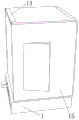
Fig. 1 is a schematic view of the overall structure of the present invention;
FIG. 2 is a schematic view of the lifting structure of the present invention;
FIG. 3 is a schematic view of the base of the present invention;
fig. 4 is a schematic view of the split of the fixing frame of the present invention.
In the figure: 1. a base; 2. a rectangular hole; 3. a circular hole; 4. a screw; 5. a strut; 501. a ball bearing; 502. a rotating shaft; 6. a bull gear; 7. a pinion gear; 8. a rotating rod; 9. an intermediate gear; 901. a chain; 10. an outer tube; 11. an inner tube; 12. a handle; 13. a roller; 14. a fixed mount; 15. a house plate.
Detailed Description
The technical solutions in the embodiments of the present invention will be described clearly and completely with reference to the accompanying drawings in the embodiments of the present invention, and it is obvious that the described embodiments are only some embodiments of the present invention, not all embodiments. Based on the embodiments in the present invention, all other embodiments obtained by a person skilled in the art without creative work belong to the protection scope of the present invention.
Referring to fig. 1-4, an installation mechanism for mobile barracks construction comprises a base 1, a rectangular hole 2 is formed on the left outer surface of the base 1, a round hole 3 is formed on the left outer surface of the base 1, the round hole 3 is located above the rectangular hole 2, a support rod 5 is fixedly connected to the lower surface of the inner cavity of the base 1, the bottoms of the support rods 5 are uniformly distributed at the four corners of the base 1, a ball bearing 501 is fixedly connected to the top of the support rod 5, the ball bearing 501 is divided into an inner ring and an outer ring, a rotating shaft 502 is fixedly connected to the inner ring inner wall of the ball bearing 501, a large gear 6 is fixedly connected to one end of the rotating shaft 502, a small gear 7 is fixedly connected to the other end of the rotating shaft 502, a chain 901 is clamped to the outer surface of the small gear 7, an intermediate gear 9 is clamped to the inner wall of the chain 901, a rotating rod 8 is fixedly connected to one end of the intermediate gear 9, and an outer tube 10 is fixedly connected to the other end of the intermediate gear 9 far away from the rotating rod 8, inner tube 11 has been cup jointed to the inner wall of outer tube 10, the inner wall that outer tube 10 passed rectangular hole 2 outwards extends, the upper surface threaded connection of inner tube 11 has handle 12, fixed surface is connected with screw rod 4 under the inner chamber of base 1, the bottom evenly distributed of screw rod 4 is in the four corners department of base 1, the fixed surface is connected with mount 14 of base 1, mount 14 divides into upper and lower two parts, the lower part inner wall fixedly connected with gyro wheel 13 of mount 14, the inner wall joint of mount 14 has room board 15.
As a technical optimization scheme of the utility model, gear wheel 6 and 7 centre of a circle departments of pinion are corresponding, can realize rotating simultaneously, and is even to 1 application of force of base, the portable barracks holistic height of lifting.
As a technical optimization scheme of the utility model, the distribution length of round hole 3 equals the hole length of rectangular hole 2, and convenient fixed handle 12 fixes the whole height in portable barracks.
As a technical optimization scheme of the utility model, pinion 7 and intermediate gear 9 are in same water flat line, and the size is the same, make things convenient for intermediate gear 9 to drive pinion 7 at both ends and carry out synchronous motion at the inner wall of chain 901.
As a technical optimization scheme of the utility model, the upper and lower two parts of handle 12 are seted up threadedly, and the drill way has been seted up to the right side one end of handle 12, adjusts the distance between handle 12 and the round hole 3 through outer tube 10 and inner tube 11, conveniently fixes handle 12 at the inner wall of round hole 3.
As a technical optimization scheme of the utility model, the right side one end of inner tube 11 is provided with the cross rod, and the cross recess has been seted up to the inner wall of outer tube 10, and the cross rod joint of inner tube 11 prevents to take place to slide between inner tube 11 and the outer tube 10 when rotatory handle 12 in the cross recess of outer tube 10, guarantees the lift effect in portable barracks.
When the utility model is used, when a user needs to install a mobile barracks and adjust the height, firstly, the house plate 15 is sequentially clamped on the inner wall of the fixing frame 14, the house plate 15 can smoothly enter the fixing frame 14 through the roller 13 of the inner wall of the fixing frame 14, after the house plate 15 is fixed, the house plate 15 and the fixing frame 14 are fixed by screws, after the house plate 15 is fixed, the whole barracks height is lifted, the lower part of the handle 12 is rotated to ensure that the orifice of the handle 12 is separated from the inner wall of the round hole 3, then the inner tube 11 is pulled to the left side, when the required length is adjusted, the handle 12 is held to rotate, the handle 12 can drive the intermediate gear 9 to carry out synchronous motion, the intermediate gear 9 drives the rotating rod 8 and the chain 901 to rotate, the pinion 7 clamped on the inner wall of the chain 901 can also carry out equidirectional motion, the ball bearings 501 are arranged between the pinion 7 and the gear 6, the bull gear 6 can rotate, and there is the meshing relation between screw rod 4 and the bull gear 6, when bull gear 6 rotated, screw rod 4 can carry out the rising motion, can realize the installation and the removal of portable barracks this moment.
For those skilled in the art, the installation mechanism for mobile barracks construction realizes the detachable function of the mobile barracks by arranging the fixed frame 14, the roller 13, the base 1 and the room plate 15, the barracks can be disassembled according to the requirement after the whole barracks are installed, the working safety of a transport driver is increased in the process of moving and transporting, the movement is convenient, the installation mechanism for the mobile barracks construction realizes the function of lifting or lowering the barracks as a whole by arranging the screw rod 4, the support rod 5, the ball bearing 501, the big gear 6, the small gear 7, the handle 12 and the chain 901, when leading to the water level to rise in the face of rainwater weather, the user can rise the base through rotatory handle 12, and the height of portable barracks base 1 of lifting prevents to be flooded by water, and the protection portable barracks does not receive the damage, has reduced user's use cost.
Furthermore, it should be understood that although the present description refers to embodiments, not every embodiment may contain only a single embodiment, and such description is for clarity only, and those skilled in the art should integrate the description, and the embodiments may be combined as appropriate to form other embodiments understood by those skilled in the art.
Claims (6)
1. The utility model provides a portable installation mechanism for barracks construction, includes base (1), its characterized in that: the outer surface of the left side of the base (1) is provided with a rectangular hole (2), the outer surface of the left side of the base (1) is provided with a round hole (3), the round hole (3) is positioned above the rectangular hole (2), a support rod (5) is fixedly connected to the lower surface of an inner cavity of the base (1), the bottoms of the support rods (5) are uniformly distributed at four corners of the base (1), a ball bearing (501) is fixedly connected to the top of the support rod (5), the ball bearing (501) is divided into an inner ring and an outer ring, a rotating shaft (502) is fixedly connected to the inner wall of the inner ring of the ball bearing (501), a large gear (6) is fixedly connected to one end of the rotating shaft (502), a small gear (7) is fixedly connected to the other end of the rotating shaft (502), a chain (901) is clamped to the outer surface of the small gear (7), and an intermediate gear (9) is clamped to the inner wall of the chain (901), one end fixedly connected with bull stick (8) of intermediate gear (9), the other end fixedly connected with outer tube (10) of bull stick (8) is kept away from in intermediate gear (9), inner tube (11) have been cup jointed to the inner wall of outer tube (10), the inner wall that rectangular hole (2) was passed in outer tube (10) outwards extends, the upper surface threaded connection of inner tube (11) has handle (12), the inner chamber lower fixed surface of base (1) is connected with screw rod (4), the bottom evenly distributed of screw rod (4) is in the four corners department of base (1), the last fixed surface of base (1) is connected with mount (14), mount (14) divide into upper and lower two parts, the lower part inner wall fixedly connected with gyro wheel (13) of mount (14), the inner wall joint of mount (14) has room board (15).
2. The mounting mechanism for mobile barracks construction according to claim 1, wherein: the circle centers of the big gear (6) and the small gear (7) are corresponding.
3. The mounting mechanism for mobile barracks construction according to claim 1, wherein: the distribution length of the round holes (3) is equal to the hole length of the rectangular holes (2).
4. The mounting mechanism for mobile barracks construction according to claim 1, wherein: the pinion (7) and the intermediate gear (9) are in the same horizontal line and are the same in size.
5. The mounting mechanism for mobile barracks construction according to claim 1, wherein: the upper part and the lower part of the handle (12) are provided with threads, and one end of the right side of the handle (12) is provided with an orifice.
6. The mounting mechanism for mobile barracks construction according to claim 1, wherein: the cross rod is arranged at one end of the right side of the inner pipe (11), a cross groove is formed in the inner wall of the outer pipe (10), and the cross rod of the inner pipe (11) is clamped in the cross groove of the outer pipe (10).
Priority Applications (1)
| Application Number | Priority Date | Filing Date | Title |
|---|---|---|---|
| CN202023193202.2U CN214195678U (en) | 2020-12-27 | 2020-12-27 | Installation mechanism is used in construction of portable barracks |
Applications Claiming Priority (1)
| Application Number | Priority Date | Filing Date | Title |
|---|---|---|---|
| CN202023193202.2U CN214195678U (en) | 2020-12-27 | 2020-12-27 | Installation mechanism is used in construction of portable barracks |
Publications (1)
| Publication Number | Publication Date |
|---|---|
| CN214195678U true CN214195678U (en) | 2021-09-14 |
Family
ID=77657130
Family Applications (1)
| Application Number | Title | Priority Date | Filing Date |
|---|---|---|---|
| CN202023193202.2U Active CN214195678U (en) | 2020-12-27 | 2020-12-27 | Installation mechanism is used in construction of portable barracks |
Country Status (1)
| Country | Link |
|---|---|
| CN (1) | CN214195678U (en) |
-
2020
- 2020-12-27 CN CN202023193202.2U patent/CN214195678U/en active Active
Similar Documents
| Publication | Publication Date | Title |
|---|---|---|
| CN214195678U (en) | Installation mechanism is used in construction of portable barracks | |
| CN214879850U (en) | Assembled interior decoration material mobile device | |
| CN214423921U (en) | Supporting structure for building engineering construction | |
| CN213629736U (en) | Stable camera support for news dissemination | |
| CN210777170U (en) | Traffic safety is with portable interim signal lamp | |
| CN111852044A (en) | Intelligent construction system for glass heat-insulation greenhouse | |
| CN213332799U (en) | Water pipe arrangement frame convenient to adjust | |
| CN219936537U (en) | Solar signal lamp convenient to assemble for traffic control | |
| CN213683139U (en) | Modular rising rack is used in top surface installation | |
| CN216619579U (en) | Liftable formula place of sports lamps and lanterns | |
| CN214530230U (en) | Externally-hung bridge construction platform | |
| CN220599080U (en) | Building construction frame | |
| CN212208780U (en) | Big screen device of wisdom building site display based on building information model | |
| CN219113466U (en) | Clamp for cutting | |
| CN217130807U (en) | Portable land mapping device | |
| CN220848967U (en) | Support frame with extending structure | |
| CN211952546U (en) | Street lamp device capable of automatically lifting | |
| CN214138621U (en) | High jacking equipment for civil engineering of security | |
| CN219931542U (en) | City building climbing rack | |
| CN211574662U (en) | Surveying and mapping device for construction | |
| CN218264836U (en) | Construction support | |
| CN219270514U (en) | Adjustable type picture hanging frame for vocational education | |
| CN220100807U (en) | Supporting device convenient to detach for installing prefabricated stairway | |
| CN218968717U (en) | Tower crane attaches wall structure | |
| CN212201213U (en) | Novel scaffold for building installation |
Legal Events
| Date | Code | Title | Description |
|---|---|---|---|
| GR01 | Patent grant | ||
| GR01 | Patent grant |