CN214189555U - Fuse box assembly and vehicle - Google Patents
Fuse box assembly and vehicle Download PDFInfo
- Publication number
- CN214189555U CN214189555U CN202022936762.6U CN202022936762U CN214189555U CN 214189555 U CN214189555 U CN 214189555U CN 202022936762 U CN202022936762 U CN 202022936762U CN 214189555 U CN214189555 U CN 214189555U
- Authority
- CN
- China
- Prior art keywords
- fuse box
- fuse
- assembly
- bracket
- main
- Prior art date
- Legal status (The legal status is an assumption and is not a legal conclusion. Google has not performed a legal analysis and makes no representation as to the accuracy of the status listed.)
- Active
Links
Images


Landscapes
- Fuses (AREA)
Abstract
The utility model provides a fuse box assembly and vehicle. The fuse box assembly can be assembled at a vehicle body of a vehicle and is used for power distribution and loop protection of a whole vehicle, wherein the fuse box assembly is provided with a main fuse box, an auxiliary fuse box, a main fuse box upper cover, an auxiliary fuse box upper cover and a bracket, wherein the main fuse box and the auxiliary fuse box are assembled on the bracket, the main fuse box upper cover and the auxiliary fuse box upper cover are respectively constructed on the main fuse box and the auxiliary fuse box to play a shielding role, a first bus bar and a second bus bar for power input are constructed in the main fuse box, and the first bus bar and the second bus bar are mutually electrically insulated and respectively led to the auxiliary fuse box.
Description
Technical Field
The utility model relates to an automobile parts technical field particularly, relates to a fuse box assembly and vehicle, especially relates to an engine compartment fuse box among vehicle power supply and the signal distribution system or automobile engine compartment electrical apparatus box.
Background
A vehicle typically has a plurality of fuse boxes, each of which is located at a different location on the vehicle. The engine compartment fuse box is a main vehicle power distribution unit of the vehicle, and completes power distribution and loop protection of the whole vehicle together with the instrument fuse box, the rear compartment fuse box and the storage battery fuse box. With the development of automobile electronic technology, vehicles integrate more and more electrical appliances, and the distribution demand of a whole automobile electronic system for a fuse box to the power supply of the electrical appliances is more and more.
At present, electrical equipment for taking electricity from an engine compartment fuse box is increasing, and when a power supply application scene requiring high reliability such as intelligent driving appears, more reliable power supply is needed.
CN1848349B provides a fuse block having an insertion port into which a dark current fuse is inserted and which is adapted to hold the dark current fuse in a mounted position, the fuse block including a guide face and an arm, the guide face being formed within the insertion port in such a manner as to be continuous from the mounted position of the dark current fuse to be in contact with the dark current fuse; the arm is formed at a position laterally of the dark current fuse in such a manner as to face the insertion port, so that the arm can hold the dark current fuse therein when the dark current fuse is in contact with the guide surface.
SUMMERY OF THE UTILITY MODEL
The utility model aims to realize the input of two solitary tunnel power, realize the power redundancy, improve electronic system's reliability.
Furthermore, the present invention also aims to solve or alleviate other technical problems existing in the prior art.
The utility model discloses a fuse box assembly and vehicle solve above-mentioned problem, particularly, according to the utility model discloses an aspect provides:
a fuse box assembly, fuse box assembly can assemble in the automobile body department of vehicle and be used for the power distribution and the return circuit protection of whole car, wherein, fuse box assembly has main fuse box, vice fuse box, main fuse box upper cover, vice fuse box upper cover and support, wherein, main fuse box with vice fuse box all assembles on the support, main fuse box upper cover with vice fuse box upper cover construct respectively on main fuse box with vice fuse box to play the effect of shielding,
first and second busbars for the supply of electrical energy are formed in the main fuse box, which are electrically insulated from one another and each lead to the secondary fuse box.
Optionally, according to an embodiment of the present invention, a water leakage hole is configured on the bottom side of the support, the water leakage hole communicates with the inner space of the support to be used for draining water, a surrounding shielding structure is arranged around the water leakage hole, the shielding structure is configured to shield the water leakage hole in a side direction and extend outwards beyond the water leakage hole.
Optionally, according to an embodiment of the present invention, a sealing flange is configured on the periphery of the main fuse box on the side connected to the support, the support is configured with a corresponding groove, and the sealing flange is connected to the groove in a shape-fitting manner.
Optionally, according to an embodiment of the present invention, one side of the main fuse box, which is connected to the bracket, is configured with a bolt extending in the direction of the bracket, the bracket is configured with a corresponding nut, the inner side of the nut is configured with a threaded hole, and the bolt is matched with the threaded hole for fixing.
Optionally, according to an embodiment of the present invention, the bolt has a flange plate and a threaded rod connected to each other, the threaded rod is configured with a thread thereon, the threaded rod is closer to the bracket than the flange plate, the flange plate and the threaded rod are configured with a protruding structure between the threads, the protruding structure extends outward beyond the threaded rod.
Optionally, according to an embodiment of the present invention, the first busbar and the second busbar are respectively configured as a copper bar.
Optionally, according to the utility model discloses an embodiment, main fuse box upper cover with vice insurance silk box upper cover respectively through buckle structure with main fuse box with vice insurance silk box is connected.
Alternatively, according to an embodiment of the present invention, the water leakage hole and the shielding structure are configured in concentric rings.
Optionally, in accordance with an embodiment of the present invention, the fuse block assembly is used in an engine compartment of a vehicle.
According to another aspect of the present invention, the utility model provides a vehicle, wherein, the vehicle has any kind of fuse box assembly of the aforesaid.
The fuse box assembly and vehicle provided benefits include: 1, the double-busbar design can support two paths of power supply input; 2, designing a water-proof structure of the water leakage hole; and 3, designing the torque attenuation prevention mechanical connection of the fuse box.
Drawings
The above and other features of the present invention will become apparent with reference to the accompanying drawings, in which,
FIG. 1 shows an overall schematic view of a fuse box assembly according to the present invention;
fig. 2 shows a schematic view of an upper cover of a secondary fuse box according to the present invention;
FIG. 3 illustrates a schematic view of a main fuse box upper cover according to the present invention;
figures 4 and 5 show schematic views of a primary fuse box and a secondary fuse box according to the present invention, respectively, from the front;
FIG. 6 shows a schematic view of a primary fuse box and a secondary fuse box according to the present invention from the bottom;
fig. 7 shows a schematic view of a stand according to the invention from the front;
fig. 8 shows a schematic view of a support according to the invention from the bottom.
Detailed Description
It is easily understood that, according to the technical solution of the present invention, a plurality of alternative structural modes and implementation modes can be proposed by those skilled in the art without changing the spirit of the present invention. Therefore, the following detailed description and the accompanying drawings are merely illustrative of the technical solutions of the present invention, and should not be considered as limiting or restricting the technical solutions of the present invention in their entirety or in any other way.
The terms of orientation of up, down, left, right, front, back, top, bottom, and the like referred to or may be referred to in this specification are defined relative to the configuration shown in the drawings, and are relative terms, and thus may be changed correspondingly according to the position and the use state of the device. Therefore, these and other directional terms should not be construed as limiting terms. Furthermore, the terms "first," "second," "third," and the like are used for descriptive and descriptive purposes only and not for purposes of indication or implication as to the relative importance of the respective components.
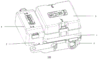
Referring to fig. 1, there is shown an overall schematic view of a fuse box assembly 100 according to the present invention.
It should be understood that the fuse box refers to a box with a fuse installed therein, and may have performance characteristics of water resistance, dust resistance, high temperature resistance, etc., and the fuse (e.g., current fuse) mainly plays a role of overload protection. Under the condition that the fuse is correctly arranged in the circuit, the fuse can be fused to cut off the current when the current is abnormally increased to a certain height and heat, and the circuit is protected from running safely. Fuses are typically in the form of a strip or sheet.
In addition, the expressions "primary" and "secondary" in the primary fuse box 1 and the secondary fuse box 2 are used only for the purpose of distinction between components, and do not represent differences in what status or importance the components referred to have between them. The main fuse box 1 and the auxiliary fuse box 2 together provide power distribution and loop protection functions of the whole vehicle. The split design of the main fuse box 1 and the auxiliary fuse box 2 can ensure that the whole fuse box assembly 100 has good heat dissipation performance. The main fuse box 1 and the auxiliary fuse box 2 can optionally have a housing made of plastic, and have the advantages of light weight, chemical stability, no corrosion, good impact resistance, good abrasion resistance, good insulation, low thermal conductivity, low processing cost and the like.
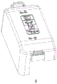
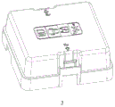
Referring to fig. 2 and 3, there are shown a schematic view of a secondary fuse box upper cover 4 according to the present invention and a schematic view of a primary fuse box upper cover 3 according to the present invention, respectively.
As can be seen from the figures, the upper sides of the two fuse box upper covers are drawn with marks, for example, to remind relevant personnel of the installation or removal direction of the corresponding upper cover, warning signs, prompts for explaining the use occasions, and the like.
Specifically, the main fuse block upper cover 3 and the sub fuse block upper cover 4 are each connected to the main fuse block 1 and the sub fuse block 2 by a snap structure. The buckle connection has the biggest characteristic that the buckle connection is convenient to mount and dismount and can be dismounted without tools, so that the assembling efficiency is high, the assembling process of the buckle position is simple, generally only one inserted action is needed, the action of rotating motion or positioning a product before assembly is not needed, and a simple and rapid assembling effect is achieved. Of course, other means of attachment, such as a threaded connection, are also optional.
For example, the latching means of the two covers can each be arranged on one side of the associated cover, while the other side is designed with a hinge, so that the two covers can each be folded or unfolded on the associated fuse box without having to be completely detached from the fuse box. The hinge structure can be realized, for example, by a hook assembly.
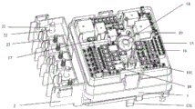
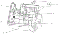
Referring to fig. 4 and 5, there are shown schematic views of a main fuse box 1 and a sub fuse box 2 according to the present invention from the front, respectively.
A first busbar 11 and a second busbar 12 for power supply input are formed in the main fuse box 1, the first busbar 11 and the second busbar 12 being electrically insulated from one another and each leading to the secondary fuse box 2.
Busbars in the electrical field, also known as busbars, etc., are used to connect a plurality of electrical lines, and are products for transmitting electrical energy, having the ability to collect and distribute electrical power. Through the design of the double busbars, two paths of power supply input can be supported. In the prior art, the fuse box is generally integrated with a bus bar to realize single power supply input, the fuse box of the application is provided with the bus bars which are double independent and mutually insulated, so that two independent power supply inputs can be realized, the power supply redundancy can be realized, and the reliability of an electronic system is improved. The first bus bar 11 and the second bus bar 12 may be arranged symmetrically to each other and respectively guided to different positions of the sub fuse box 2.
Furthermore, the first busbar 11 and the second busbar 12 can be configured as a copper bar, respectively. The copper busbar is also called as a copper busbar, and has high mechanical properties, good electrical conductivity, thermal conductivity, excellent corrosion resistance, electroplating property, brazing property, good forming processability and the like. And meanwhile, the cost is lower.
Illustratively, the fuse box is further assembled and combined by a heat dissipation fin, a two-pin fuse 15, a three-pin fuse 16, a Mcase + fuse 17, a LP Jcase fuse 18, a relay 19, a fuse plug 101, a combined fuse 21, a printed circuit board assembly 102, an M8 bolt 22, an M6 bolt 23, a fuse clip, a terminal stabilizer, and the like. The first bus bar 11 and the second bus bar 12 are integrated on the pcb assembly 102, and the two-way bus bar realizes two-way power input. The harness terminal at the sub fuse box 2 is connected with the combination fuse 21 through a fastener. It can be seen that the bolt includes two specifications, M8 and M6, corresponding to the MEGA and MIDI fuses of the combination fuse, respectively. The square heads of the bolts 22 and 23 are fitted into the grooves of the sub fuse box 2. The combined fuse 21 includes 2 MEGA fuses and 5 MIDI fuses, the rated value of the MEGA fuse is 250A-500A, and the rated value of the MIDI fuse is 80A-125A. These other parts are not described in detail herein, as they are not material to the present application.
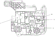
Referring to fig. 6 and 7, there are shown a schematic view of a main fuse box 1 and a secondary fuse box 2 according to the present invention from the bottom and a schematic view of a bracket 5 according to the present invention from the front, respectively.
A sealing flange 13 is formed on the outer circumference of the main fuse box 1 on the side connected to the carrier 5, the carrier 5 is formed with a corresponding recess 53, and the sealing flange 13 is connected to the recess 53 in a form-fitting manner. The sealing flanging 13 is matched with the groove 53, so that the fuse box and the bracket 5 are positioned and are waterproof.
It is possible for the sealing collar 13 to be of substantially square or rectangular configuration and to be provided at one or more of its four corners with a stud 131, which stud 131 is form-fit in a corresponding notch configured in the holder, in such a way that the positional stability between the fuse box and the holder 5 can be increased.
It is also possible for the sealing bead 13 to be designed as a double-layer choke ring, while the recess 53 is correspondingly also formed by a double-layer structure. The double structure of the sealing flange 13 grips the inner wall of the groove 53 when the sealing flange 13 is fitted with the groove 53. The waterproof effect can be better realized through the structure and the assembly design.
In addition to the positioning, the present application also provides a fixing effect of the fuse block to the holder 5. Specifically, a bolt 14 extending in the direction of the bracket 5 is formed on the side of the main fuse box 1 connected to the bracket 5, a corresponding nut 54 is formed on the bracket 5, a threaded hole is formed on the inner side of the nut 54, and the bolt 14 is engaged with the threaded hole to be fixed.
A threaded fastener (e.g., a bolt) is a mechanical component that is either internally or externally threaded and is commonly used as a fastener to facilitate the assembly of multiple components. The most common threaded fasteners are screws, nuts and bolts. However, other threaded fasteners are also available, such as cage nuts, threaded inserts, threaded rods, and the like. The thread fastening connection is a detachable fixed connection which is widely used, and has the advantages of simple structure, reliable connection, convenient assembly and disassembly and the like. Including but not limited to bolted connections, screwed connections, fastener-pack connections (e.g., externally threaded fasteners and washers); meanwhile, the specific form of the thread can be a triangular thread (common or imperial), a cylindrical pipe thread, a rectangular thread, and the like.
Thus, for example, the fuse box can be positioned with respect to the bracket 5 by the engagement between the sealing flange 13 and the recess 53, and then the fuse box can be fixed with respect to the bracket 5 by the engagement between the bolt 14 and the nut 54. In particular, a single bolt 14 can accomplish this securing effect, resulting in material and cost savings.
Through the connection mode, the fuse box (namely the column (main) fuse box 1 and the auxiliary fuse box 2) and the bracket 5 are centered and positioned through the mechanical guide structure, so that the requirement that the connector of the fuse box needs to be reliably and electrically connected with the fuse box is met. In particular, the centering of these components is performed after the wiring harness insert has been installed.
Furthermore, the screw 14 has a flange and a threaded shaft which are connected to one another, a thread being formed on the threaded shaft, the threaded shaft being closer to the holder 5 than the flange, a projection 141 being formed between the flange and the thread of the threaded shaft, the projection 141 extending beyond the threaded shaft in an outward direction (i.e. radially outward with respect to the threaded shaft).
The flange can also be seen in fig. 4, while the projection 141 can be seen in fig. 6. The mechanical connection of the fuse box against torque attenuation is formed by the raised structure 141. Specifically, the fuse box and the bracket 5 are connected by using a bolt and a nut with a convex structure, so that the torque attenuation can be prevented, the utilization rate of the connector can be improved, and the structural size of the fuse box and the bracket 5 can be reduced. That is, when the fuse box is fixed to the bracket 5, the protrusion 141 is in rigid contact with the fastening member (e.g., nut), and can exert a pre-load force on the fastening surfaces of the bolt and the nut, thereby preventing the torque from being attenuated. Therefore, the advantages of small deformation and good torque can be brought.
In order to mount the bracket 5 to the vehicle body, bolt mounting holes 55, 56, and 57 are integrated in the bracket 5, and the mounting and fastening of the fuse block assembly 100 and the physical structure of the vehicle body are achieved through the three mounting holes. Illustratively, the three bolt mounting holes are respectively configured at the upper right, lower left, and lower right of the bracket 5, and have different shapes and sizes so as to match with the respective positions of the vehicle body, and a reinforcing structure is configured at the bottom surface positions of the bracket 5 corresponding to the mounting holes. The rest of the support 5 is also filled with a reinforcing structure.
With reference to fig. 8, a schematic view of a support 5 according to the invention is shown from the bottom.
A water leakage hole 51 is formed on the bottom side of the bracket 5, the water leakage hole 51 communicates with the inner space of the bracket 5 for draining water, a surrounding shielding structure 511 is arranged around the water leakage hole 51, and the shielding structure 511 is configured to shield the water leakage hole 51 in the lateral direction and extend outward beyond the water leakage hole 51.
The water leakage hole 51 can be used not only for draining water from the fuse box and the holder 5 but also for draining water entering from the outside of the fuse box assembly 100. The water leakage holes 51 can be arranged in plural on the bottom side of the bracket 5 to improve drainage capacity and drainage area coverage.
The shielding structure 511 is used to limit the intrusion angle of water intruding from the outside of the fuse box assembly 100, because the shielding structure 511 covers the side surface of the water leakage hole 51 and further extends outward (i.e., in the direction away from the bottom side) beyond the edge of the water leakage hole 51, the external water must first bypass the coverage area of the shielding structure 511 to possibly intrude into the inside of the holder 5 through the water leakage hole 51. In this respect, by designing a water splashing prevention shielding structure around the water leakage hole, the incident angle range of the water column which can be sprayed into the water leakage hole can be reduced, and the water prevention performance is greatly improved. In the prior art, when the water leakage hole on the base of the fuse box is splashed by the water column, the water leakage hole has the problem that the water column can be splashed into the fuse box due to the limitation of the production process of the injection molding part.
It can also be seen from the figures that the water leakage holes 51 and the shielding structure 511 are configured in concentric rings. This design is simple for the manufacture of the water leakage hole 51 and the shielding structure 511, and these two members can be manufactured together without separate and separate manufacture, which also saves time and money costs for the manufacture. In addition, an important feature of the circular or circular shape is that the circular shape has a larger area than other polygons for a given circumference, or the circular shape has a smaller circumference for the same area, which results in material savings over the square shape. This advantage is also provided by the water leakage holes and the shielding structure of this shape.
In addition, a fabrication hole plug 52 formed by drawing a connector buckling structure is integrated on the bottom side of the bracket 5. The fabrication hole stopper 52 may be understood as a plug for fitting into and blocking an opening (i.e., fabrication hole) in the bottom side of the support 5 for the purpose of waterproofing. The fabrication hole plugs 52 may be configured as cubes, spheres, cube + half-round combinations or any regular or irregular shape suitable for the opening.
Furthermore, the fuse block assembly 100 may be used in, i.e. may be arranged at, the engine compartment of the engine. Of course, the fuse box assembly 100 can be disposed at other locations of the vehicle, including the cabin and the like.
It should be understood that the fuse block assembly of the present invention may be mounted on a variety of vehicles, including gasoline vehicles, diesel vehicles, cars, trucks, buses, hybrid vehicles, and electric vehicles, among others. Accordingly, the subject matter of the present invention is also directed to protecting various vehicles equipped with the fuse box assembly of the present invention.
Embodiments and advantages of the vehicle are described in detail with respect to the fuse box assembly.
In summary, the present application provides a fuse box for an automobile (e.g., for an engine compartment), which improves the mechanical and electrical connection design of the fuse box, and designs a redundant power supply system, thereby not only facilitating the reduction of the size of the box, the miniaturization of parts, and the weight reduction, but also achieving the purposes of saving materials, increasing the versatility and reducing the cost, and having convenience of use or maintenance, safety and reliability.
It should be understood that all of the above preferred embodiments are exemplary and not restrictive, and that various modifications and changes in the specific embodiments described above, which may occur to those skilled in the art upon reading the teachings of the present invention, are intended to be within the scope of the appended claims.
Claims (10)
1. A fuse box assembly (100), the fuse box assembly (100) can be assembled at the body of the vehicle and used for power distribution and circuit protection of the whole vehicle, characterized in that, the fuse box assembly (100) has a main fuse box (1), a sub fuse box (2), a main fuse box upper cover (3), a sub fuse box upper cover (4) and a bracket (5), wherein, the main fuse box (1) and the sub fuse box (2) are assembled on the bracket (5), the main fuse box upper cover (3) and the sub fuse box upper cover (4) are respectively constructed on the main fuse box (1) and the sub fuse box (2) to play a shielding role,
a first busbar (11) and a second busbar (12) for the supply of electrical energy are formed in the main fuse box (1), the first busbar (11) and the second busbar (12) being electrically insulated from one another and each leading to the secondary fuse box (2).
2. The fuse box assembly (100) according to claim 1, characterized in that a water leakage hole (51) is configured on the bottom side of the bracket (5), the water leakage hole (51) communicates with the inner space of the bracket (5) for draining water, a surrounding shielding structure (511) is arranged around the water leakage hole (51), and the shielding structure (511) is configured to shield the water leakage hole (51) in the lateral direction and extend outwards beyond the water leakage hole (51).
3. Fuse block assembly (100) according to claim 1, characterized in that a sealing bead (13) is formed on the periphery of the main fuse block (1) on the side connected to the carrier (5), the carrier (5) being formed with a corresponding recess (53), the sealing bead (13) being connected to the recess (53) in a form-fitting manner.
4. The fuse block assembly (100) according to claim 1 or 3, characterized in that a bolt (14) extending in the direction of the bracket (5) is formed on the side of the main fuse block (1) connected to the bracket (5), the bracket (5) is formed with a corresponding nut (54), a threaded hole is formed on the inner side of the nut (54), and the bolt (14) is fitted into the threaded hole for fixing.
5. The fuse block assembly (100) of claim 4, characterized in that the bolt (14) has a flange and a threaded shaft connected to each other, the threaded shaft having a thread formed thereon, the threaded shaft being closer to the bracket (5) than the flange, a raised structure (141) being formed between the flange and the thread of the threaded shaft, the raised structure (141) extending outwardly beyond the threaded shaft.
6. The fuse block assembly (100) of claim 1, characterized in that the first busbar (11) and the second busbar (12) are each configured as a copper bar.
7. The fuse block assembly (100) according to claim 1, wherein the main fuse block upper cover (3) and the sub fuse block upper cover (4) are each connected with the main fuse block (1) and the sub fuse block (2) by a snap-fit structure.
8. The fuse box assembly (100) according to claim 2, wherein the water leakage hole (51) and the shielding structure (511) are configured in concentric rings.
9. The fuse block assembly (100) of claim 1, wherein the fuse block assembly (100) is for an engine compartment of a vehicle.
10. A vehicle having a fuse box assembly (100) according to any one of claims 1 to 9.
Priority Applications (1)
| Application Number | Priority Date | Filing Date | Title |
|---|---|---|---|
| CN202022936762.6U CN214189555U (en) | 2020-12-10 | 2020-12-10 | Fuse box assembly and vehicle |
Applications Claiming Priority (1)
| Application Number | Priority Date | Filing Date | Title |
|---|---|---|---|
| CN202022936762.6U CN214189555U (en) | 2020-12-10 | 2020-12-10 | Fuse box assembly and vehicle |
Publications (1)
| Publication Number | Publication Date |
|---|---|
| CN214189555U true CN214189555U (en) | 2021-09-14 |
Family
ID=77650583
Family Applications (1)
| Application Number | Title | Priority Date | Filing Date |
|---|---|---|---|
| CN202022936762.6U Active CN214189555U (en) | 2020-12-10 | 2020-12-10 | Fuse box assembly and vehicle |
Country Status (1)
| Country | Link |
|---|---|
| CN (1) | CN214189555U (en) |
-
2020
- 2020-12-10 CN CN202022936762.6U patent/CN214189555U/en active Active
Similar Documents
| Publication | Publication Date | Title |
|---|---|---|
| JP6390679B2 (en) | Power converter | |
| CN202172544U (en) | Mechanical structure for automotive controller | |
| US8395061B2 (en) | Electrical junction box | |
| CN202522828U (en) | Camera module for vehicle | |
| CN205752316U (en) | Automobile batteries bag | |
| US20140041891A1 (en) | Electric box for vehicle | |
| CN104619154B (en) | Electric automobile auxiliary control device | |
| CN214189555U (en) | Fuse box assembly and vehicle | |
| US11019740B2 (en) | Electrical connection box | |
| US20190115702A1 (en) | Power distribution box | |
| CN215769409U (en) | Case and input/output signal device for locomotive network | |
| KR100755031B1 (en) | Fuse box mounting structure for battery | |
| CN215301106U (en) | Rear domain controller for pure electric vehicle | |
| CN112993617B (en) | All-in-one motor controller assembly integrated with electronic pump controller | |
| CN219418942U (en) | Fuse box for battery pack | |
| CN205211692U (en) | Miniaturized battery fuse box | |
| CN217239375U (en) | Fuse box | |
| CN221080650U (en) | Waterproof type high-voltage distribution box body and distribution box | |
| CN212783363U (en) | High-protection high-power fuse box | |
| CN211929426U (en) | High-efficient integrated car fuse block | |
| CN219487316U (en) | TCU installing support and have its vehicle | |
| CN218385862U (en) | Welding type bolt power-on waterproof module | |
| CN219833419U (en) | Flywheel energy storage control cabinet | |
| CN218888049U (en) | Integrated distribution box | |
| CN219738895U (en) | Deconcentrator with self-fusing mechanism |
Legal Events
| Date | Code | Title | Description |
|---|---|---|---|
| GR01 | Patent grant | ||
| GR01 | Patent grant |