CN214186455U - End face machining device convenient for spring production - Google Patents
End face machining device convenient for spring production Download PDFInfo
- Publication number
- CN214186455U CN214186455U CN202022702664.6U CN202022702664U CN214186455U CN 214186455 U CN214186455 U CN 214186455U CN 202022702664 U CN202022702664 U CN 202022702664U CN 214186455 U CN214186455 U CN 214186455U
- Authority
- CN
- China
- Prior art keywords
- base
- servo motor
- plate
- spring production
- spring
- Prior art date
- Legal status (The legal status is an assumption and is not a legal conclusion. Google has not performed a legal analysis and makes no representation as to the accuracy of the status listed.)
- Active
Links
Images


Abstract
The utility model discloses a terminal surface processingequipment is used in spring production convenient to, which comprises a base, base and roof, the bottom of base is connected with supports rubberpost, the bottom of supporting rubberpost is equipped with the rubber cushion, be equipped with in the inside groove of base and inhale shake seat, backup pad and base are installed respectively to the top of base, the both sides of base are equipped with the mobile station respectively, be equipped with the connecting rod between the mobile station, dock leveler and servo motor are installed respectively to the top of two mobile stations, dock leveler and servo motor all are connected with the fixed plate through the rotation axis, install spacing briquetting on the fixed plate, the inboard of backup pad is connected with electric telescopic handle. The utility model provides a be convenient for terminal surface processingequipment is used in spring production, through setting up servo motor and rotation axis, after the one side is polished and is accomplished, starts servo motor, and servo motor drives a side fixing plate rotatory, and the opposite side fixing plate produces synchronous revolution through the rotation axis simultaneously, will process the spring and rotate, has realized automatic positioning, has improved work efficiency greatly.
Description
Technical Field
The utility model relates to a spring processingequipment design field specifically is a terminal surface processingequipment is used in spring production of being convenient for.
Background
A spring is a mechanical part that works by elasticity. The part made of elastic material deforms under the action of external force and restores to the original shape after the external force is removed. Also used as a "spring". Typically made of spring steel. The types of springs are complex and various, and mainly include spiral springs, volute springs, plate springs, special springs and the like according to the shapes.
In the course of working to the spring, often need polish to the terminal surface of spring, the staff all utilizes terminal surface processingequipment to polish to the work piece usually, but most terminal surface processingequipment can not automatically regulated spring position, needs artifical manual regulation, can take place the danger of tong often and efficiency is not high, consequently needs a terminal surface processingequipment for the spring production of being convenient for.
SUMMERY OF THE UTILITY MODEL
An object of the utility model is to provide a terminal surface processingequipment is used in spring production of being convenient for to provide in solving above-mentioned background art because in the course of working to the spring, often need polish to the terminal surface of spring, the staff all utilizes terminal surface processingequipment to polish to the work piece usually, but most terminal surface processingequipment can not the automatically regulated spring position, needs artifical manual regulation, can take place the danger of tong often and the problem that efficiency is not high.
In order to achieve the above object, the utility model provides a following technical scheme: a terminal surface processing device convenient for spring production comprises a base, a base and a top plate, wherein the bottom end of the base is connected with a supporting grinding column, the bottom end of the supporting grinding column is provided with a rubber cushion, an inner groove of the base is provided with a shock absorption seat, the top end of the base is respectively provided with a support plate and a base, two sides of the base are respectively provided with a mobile station, a connecting rod is arranged between the mobile stations, the top ends of the two mobile stations are respectively provided with a butt plate and a servo motor, the butt plate and the servo motor are both connected with a fixed plate through a rotating shaft, a limit pressing block is arranged on the fixed plate, the inner side of the support plate is connected with an electric telescopic rod, the top end of the electric telescopic rod is fixedly connected to the side surface of the mobile station, the bottom end of the mobile station is provided with a sliding block, the top plate is fixedly arranged at the top end of the support plate, the bottom end of the top plate is fixedly connected with a pushing pressure cylinder, the bottom of propelling movement jar is connected with the lift push rod, the bottom of lift push rod is equipped with high-speed rotating electrical machines, the bottom of high-speed rotating electrical machines is connected with the emery wheel, be equipped with the articulated shaft on the front view face of roof, articulated shaft fixedly connected with splash guard, electric fan is installed in the outside of backup pad, electric fan connects the inboard air guide box of backup pad.
Preferably, the rubber cushion closely pastes with the bottom surface that supports the whetstone, inhale the shake seat and pass through welded fastening with the upper and lower end of the inside groove of base, inhale the shake seat and be equipped with a plurality of and equidistance and distribute.
Preferably, the connecting rod is installed between two mobile stations through the mode that the draw-in groove is connected, servo motor and fixed plate are fixed connection, the butt joint board forms swivelling joint through rotation axis and fixed plate.
Preferably, the fixed plates are symmetrically distributed relative to the base, and the limiting pressing blocks correspond to the thread grooves through threaded holes and are fixed through bolts.
Preferably, the sliding block moves horizontally and linearly in the sliding groove in the base, and the moving platform moves by pushing the sliding block through the electric telescopic rod.
Preferably, the splash-proof plate and the top plate form a structure capable of being turned over up and down through a hinge shaft, and a transparent observation plastic plate is installed inside the splash-proof plate.
Preferably, a plurality of air guide nozzles are arranged on the side face of the air guide box, and the air guide box and the electric fan can be in mutual air circulation.
Compared with the prior art, the beneficial effects of the utility model are that: by arranging the servo motor and the rotating shaft, after one surface is polished, the servo motor is started, the servo motor drives the fixing plate on one side to rotate, and meanwhile, the fixing plate on the other side synchronously rotates through the rotating shaft to rotate the processing spring, so that automatic position adjustment is realized, the working efficiency is greatly improved, the clamping groove connection can be used for conveniently disassembling and replacing the connecting rod when the blind length spring is processed, and the applicability is improved;
(1) the end face machining device for producing the spring conveniently comprises a rubber cushion and a shock absorption seat, wherein the rubber cushion can reduce the pressure applied to a supporting grinding column by a base in the polishing process and prevent the supporting grinding column from being damaged;
(2) a spring is placed on two fixing plates by arranging a fixing plate and a limiting pressing block, the limiting pressing block is adjusted to be stable, and then the limiting pressing block is fixed by using a bolt, so that the machining spring can be well fixed and limited, and the machining accuracy is prevented from being influenced by shaking in the machining process;
(3) the utility model provides a terminal surface processingequipment is used in spring production convenient to, through setting up slider and electric telescopic handle, adds man-hour when needs are to the same different positions in face of spring, starts electric telescopic handle and promotes the slider and remove in the spout, and the slider drives the mobile station and is horizontal migration, alright automatic adjustment spring's position, and is very convenient.
Drawings
Fig. 1 is a schematic front view of the internal structure of the present invention;
fig. 2 is a schematic front view of the structure of the present invention;
fig. 3 is an enlarged schematic view of the utility model at a;
fig. 4 is an enlarged schematic view of the position B of the present invention.
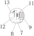
In the figure: 1. a base; 2. supporting the grinding column; 3. a rubber cushion; 4. a shock absorbing seat; 5. a support plate; 6. a base; 7. a mobile station; 8. a connecting rod; 9. a servo motor; 10. a butt plate; 11. a rotating shaft; 12. a fixing plate; 13. a limiting pressing block; 14. an electric telescopic rod; 15. a slider; 16. a top plate; 17. a pushing pressure cylinder; 18. lifting the pushing rod; 19. a high-speed rotating electrical machine; 20. grinding a grinding wheel; 21. hinging a shaft; 22. a splash-proof plate; 23. an electric fan; 24. and a wind guide box.
Detailed Description
The technical solutions in the embodiments of the present invention will be described clearly and completely with reference to the accompanying drawings in the embodiments of the present invention, and it is obvious that the described embodiments are only some embodiments of the present invention, not all embodiments. Based on the embodiments in the present invention, all other embodiments obtained by a person skilled in the art without creative work belong to the protection scope of the present invention.
Referring to fig. 1-4, a terminal surface processing device for producing springs conveniently comprises a base 1, a base 6 and a top plate 16, wherein the bottom end of the base 1 is connected with a supporting column 2, the bottom end of the supporting column 2 is provided with a rubber cushion 3, an inner groove of the base 1 is provided with a shock absorbing seat 4, the top end of the base 1 is respectively provided with a supporting plate 5 and a base 6, the two sides of the base 6 are respectively provided with a mobile station 7, a connecting rod 8 is arranged between the mobile stations 7, the top ends of the two mobile stations 7 are respectively provided with a butt plate 10 and a servo motor 9, the butt plate 10 and the servo motor 9 are both connected with a fixed plate 12 through a rotating shaft 11, the fixed plate 12 is provided with a limit pressing block 13, the inner side of the supporting plate 5 is connected with an electric telescopic rod 14, the top end of the electric telescopic rod 14 is fixedly connected to the side surface of the mobile station 7, the bottom end of the moving platform 7 is provided with a sliding block 15, the top plate 16 is fixedly installed at the top end of the supporting plate 5, the bottom end of the top plate 16 is fixedly connected with a pushing cylinder 17, the bottom end of the pushing cylinder 17 is connected with a lifting pushing rod 18, the bottom end of the lifting pushing rod 18 is provided with a high-speed rotating motor 19, the bottom end of the high-speed rotating motor 19 is connected with a grinding wheel 20, a hinged shaft 21 is arranged on the front view plane of the top plate 16, the hinged shaft 21 is fixedly connected with a sputtering-preventing plate 22, the outer side of the supporting plate 5 is provided with an electric fan 23, and the electric fan 23 is connected with an air guide box 24 on the inner side of the supporting plate 5;
specifically, the rubber cushion 3 is closely attached to the bottom end surface of the grinding column 2, the shock absorbing seat 4 is fixed to the upper end and the lower end of the inner groove of the base 1 by welding, the shock absorbing seat 4 is provided with a plurality of rubber cushions which are distributed at equal intervals, and the rubber cushion 3 can reduce the pressure applied to the supporting grinding column 2 by the base 1 in the polishing process by installing the rubber cushion 3 and the shock absorbing seat 4, so that the supporting grinding column 2 is prevented from being damaged, and the shock absorbing seat 4 can reduce the vibration force generated in the polishing process and maintain the stability of the operation of the equipment;
specifically, the connecting rod 8 is installed between the two mobile stations 7 in a clamping groove connection mode, the servo motor 9 is fixedly connected with the fixed plate 12, the butt joint plate 10 is rotatably connected with the fixed plate 12 through the rotating shaft 11, the servo motor 9 and the rotating shaft 11 are arranged, after one surface is polished, the servo motor 9 is started, the servo motor 9 drives the fixed plate 12 on one side to rotate, meanwhile, the fixed plate 12 on the other side synchronously rotates through the rotating shaft 11 to rotate the processing spring, automatic position adjustment is achieved, the working efficiency is greatly improved, the clamping groove connection can facilitate the disassembly and replacement of the connecting rod 8 when the length spring is not processed, and the applicability is improved;
specifically, the fixing plates 12 are symmetrically distributed about the base 6, the limiting pressing blocks 13 correspond to the thread grooves through threaded holes and are fixed through bolts, the springs are placed on the two fixing plates 12 through the fixing plates 12 and the limiting pressing blocks 13, the limiting pressing blocks 13 are fixed 13 through the bolts after the springs are stabilized by adjusting the positions of the limiting pressing blocks 13, and therefore the springs can be well fixed and limited, shaking in the machining process is prevented, and machining accuracy is not affected;
specifically, the sliding block 15 makes a horizontal linear motion in a sliding groove in the base 6, the moving platform 7 moves by pushing the sliding block 15 through the electric telescopic rod 14, and by arranging the sliding block 15 and the electric telescopic rod 14, when different positions on the same surface of the spring need to be machined, the electric telescopic rod 14 is started to push the sliding block 15 to move in the sliding groove, and the sliding block 15 drives the moving platform 7 to make a horizontal movement, so that the position of the spring can be automatically adjusted, and the device is very convenient;
specifically, the anti-sputtering plate 22 and the top plate 16 form a structure of turning up and down through the hinge shaft 21, a transparent observation plastic plate is installed inside the anti-sputtering plate 22, and by arranging the anti-sputtering plate 22, the anti-sputtering plate 22 is pulled down through the hinge shaft 21 during polishing, so that scraps and sparks generated by polishing can be well isolated, and the transparent observation plastic plate can conveniently observe the polishing condition and is very convenient;
specifically, the side of air guide box 24 is equipped with a plurality of air guide nozzles, but the circulation of gas mutually between air guide box 24 and the electric fan 23 through setting up air guide box 24 and electric fan 23, the in-process of polishing can produce a lot of smog granules, influences sight and staff healthy, starts electric fan 23 this moment, blows the air current into air guide box 24 in, a plurality of air guide nozzles that are equipped with in the side through air guide box 24 blow off the air current compression, blow away smog can.
The working principle is as follows: at first through setting up fixed plate 12 and spacing briquetting 13, place the spring on two fixed plates 12, adjust the position with spacing briquetting 13 and make the spring firm back, use the bolt to fix spacing briquetting 13, can carry out fine fixed and spacing to the processing spring like this, prevent the in-process shake of processing, influence the precision of processing, start propelling movement pressure cylinder 17 and high-speed rotating electrical machines 19, lift propelling movement pole 18 drives rotatory dull polish wheel 20 and polishes the spring, through installation rubber cushion 3 and inhale shake seat 4, rubber cushion 3 can reduce the pressure that polishing in-process base 1 applyed to supporting whetstone 2, prevent to support whetstone 2 and damage, and inhale shake seat 4 and can reduce the vibrations power that polishing in-process produced, the stability of maintenance equipment function.
Then add man-hour when needs are to the same face different positions of spring, start electric telescopic handle 14 and promote slider 15 and remove in the spout, slider 15 drives mobile station 7 and is horizontal migration, the position of alright automatic adjustment spring, it is very convenient, after the completion is polished to the one side, start servo motor 9, servo motor 9 drives one side fixed plate 12 rotatory, opposite side fixed plate 12 produces synchronous revolution through rotation axis 11 simultaneously, it is rotatory to process the spring, automatic positioning has been realized, work efficiency is greatly improved, and the draw-in groove connection can add man-hour to the length spring of not leading to, it is all very convenient to the dismantlement and the change of connecting rod 8, improve the suitability.
At last when polishing will prevent that splash board 22 pulls down through articulated shaft 21, alright with the piece and the spark isolation that will polish the production fine, and transparent observation plastic slab can conveniently observe the condition of polishing, it is very convenient, and can produce a lot of smog granules among the polishing process, influence sight and staff health, start electric fan 23 this moment, blow the air current into air guide box 24 in, a plurality of air guide nozzles that are equipped with through air guide box 24' S side blow off the air current compression, blow away smog can, servo motor 9 model is YE2-132S-4 in this case, propelling movement pressure cylinder 17 model is CDM2B25, high-speed rotating electrical machines 19 model is MSMA3 AZC.
It is obvious to a person skilled in the art that the invention is not restricted to details of the above-described exemplary embodiments, but that it can be implemented in other specific forms without departing from the spirit or essential characteristics of the invention. The present embodiments are therefore to be considered in all respects as illustrative and not restrictive, the scope of the invention being indicated by the appended claims rather than by the foregoing description, and all changes which come within the meaning and range of equivalency of the claims are therefore intended to be embraced therein. Any reference sign in a claim should not be construed as limiting the claim concerned.
Claims (7)
1. The utility model provides a be convenient for end face processingequipment is used in spring production, includes base (1), base (6) and roof (16), its characterized in that: the bottom of base (1) is connected with support grinding column (2), the bottom of support grinding column (2) is equipped with rubber cushion (3), be equipped with in the inside groove of base (1) and inhale shake seat (4), backup pad (5) and base (6) are installed respectively to the top of base (1), the both sides of base (6) are equipped with mobile station (7) respectively, be equipped with connecting rod (8) between mobile station (7), butt plate (10) and servo motor (9) are installed respectively to the top of two places mobile station (7), butt plate (10) and servo motor (9) all are connected with fixed plate (12) through rotation axis (11), install spacing briquetting (13) on fixed plate (12), the inboard of backup pad (5) is connected with electric telescopic handle (14), the top fixed connection of electric telescopic handle (14) is in the side of mobile station (7), the bottom of mobile station (7) is equipped with slider (15), roof (16) fixed mounting is on the top of backup pad (5), the bottom fixedly connected with propelling movement of roof (16) is pressed jar (17), the bottom that the propelling movement pressed jar (17) is connected with lift push rod (18), the bottom of lift push rod (18) is equipped with high-speed rotating electrical machines (19), the bottom of high-speed rotating electrical machines (19) is connected with dull polish wheel (20), be equipped with articulated shaft (21) on the front view face of roof (16), articulated shaft (21) fixedly connected with anti-sputtering board (22), electric fan (23) are installed in the outside of backup pad (5), wind guide box (24) of backup pad (5) inboard are connected in electric fan (23).
2. The end face machining device convenient for spring production according to claim 1, characterized in that: rubber cushion (3) closely pastes with the bottom surface of support column (2), inhale the upper and lower end of inhaling the inside groove of shake seat (4) and base (1) and pass through welded fastening, it is equipped with a plurality of and equidistance distribution to inhale shake seat (4).
3. The end face machining device convenient for spring production according to claim 1, characterized in that: connecting rod (8) are installed between two mobile stations (7) through the mode that the draw-in groove is connected, servo motor (9) are fixed connection with fixed plate (12), butt joint board (10) form swivelling joint through rotation axis (11) and fixed plate (12).
4. The end face machining device convenient for spring production according to claim 1, characterized in that: the fixing plates (12) are symmetrically distributed relative to the base (6), and the limiting pressing blocks (13) correspond to the thread grooves through threaded holes and are fixed through bolts.
5. The end face machining device convenient for spring production according to claim 1, characterized in that: the sliding block (15) moves horizontally and linearly in a sliding groove in the base (6), and the moving platform (7) moves by pushing the sliding block (15) through the electric telescopic rod (14).
6. The end face machining device convenient for spring production according to claim 1, characterized in that: the splash-proof plate (22) forms a structure of turning up and down through a hinged shaft (21) and a top plate (16), and a transparent observation plastic plate is installed inside the splash-proof plate (22).
7. The end face machining device convenient for spring production according to claim 1, characterized in that: a plurality of air guide nozzles are arranged on the side surface of the air guide box (24), and the air guide box (24) and the electric fan (23) can be in mutual air circulation.
Priority Applications (1)
| Application Number | Priority Date | Filing Date | Title |
|---|---|---|---|
| CN202022702664.6U CN214186455U (en) | 2020-11-20 | 2020-11-20 | End face machining device convenient for spring production |
Applications Claiming Priority (1)
| Application Number | Priority Date | Filing Date | Title |
|---|---|---|---|
| CN202022702664.6U CN214186455U (en) | 2020-11-20 | 2020-11-20 | End face machining device convenient for spring production |
Publications (1)
| Publication Number | Publication Date |
|---|---|
| CN214186455U true CN214186455U (en) | 2021-09-14 |
Family
ID=77646567
Family Applications (1)
| Application Number | Title | Priority Date | Filing Date |
|---|---|---|---|
| CN202022702664.6U Active CN214186455U (en) | 2020-11-20 | 2020-11-20 | End face machining device convenient for spring production |
Country Status (1)
| Country | Link |
|---|---|
| CN (1) | CN214186455U (en) |
Cited By (1)
| Publication number | Priority date | Publication date | Assignee | Title |
|---|---|---|---|---|
| CN114952554A (en) * | 2022-06-20 | 2022-08-30 | 武汉船用机械有限责任公司 | Automatic grinding device |
-
2020
- 2020-11-20 CN CN202022702664.6U patent/CN214186455U/en active Active
Cited By (2)
| Publication number | Priority date | Publication date | Assignee | Title |
|---|---|---|---|---|
| CN114952554A (en) * | 2022-06-20 | 2022-08-30 | 武汉船用机械有限责任公司 | Automatic grinding device |
| CN114952554B (en) * | 2022-06-20 | 2023-07-21 | 武汉船用机械有限责任公司 | Automatic polishing device |
Similar Documents
| Publication | Publication Date | Title |
|---|---|---|
| CN112247256B (en) | Aluminum profile machining system | |
| CN214186455U (en) | End face machining device convenient for spring production | |
| CN115319273A (en) | Laser welding equipment with real-time cleaning welding face | |
| CN218984265U (en) | Small part rapid machining operation table | |
| CN218745180U (en) | Synchronous deburring cutting platform of steel construction | |
| CN211163357U (en) | Steel belt grinding machine | |
| CN210255421U (en) | Adjustable cylindrical grinding machine | |
| CN113634995A (en) | Automatic cutting and grinding process for slag ingot dummy plate | |
| CN208826304U (en) | A kind of tent processing polishing grinding device | |
| CN214817369U (en) | Polishing machine capable of automatically clamping and used for bucket tooth production | |
| CN114193267A (en) | Equipment for removing burrs on inner surface and outer surface of spring and working method thereof | |
| CN211249546U (en) | Five metals grinding device who facilitates use | |
| CN208826259U (en) | Grinding device is used in a kind of production of metal product | |
| CN209919833U (en) | Assembled electromechanical device maintenance device | |
| CN108655910B (en) | A kind of flexibly adjustable auto repair grinding machine | |
| CN218312389U (en) | Special grinding device for old knife | |
| CN209303775U (en) | A kind of milling machine for collecting processing waste material | |
| CN112223502A (en) | Fettling device is used in porcelain insulator processing | |
| CN215617185U (en) | Metal character shell polisher | |
| CN210944719U (en) | Emergency generator mobile device | |
| CN219255157U (en) | Protection type steel polisher | |
| CN213105926U (en) | Mutual inductor plane grinding device | |
| CN213673189U (en) | Multifunctional clamp for knife grinder | |
| CN211490892U (en) | Polishing equipment for producing bicycle part frame fork | |
| CN220178258U (en) | Double-end-face horizontal milling machine |
Legal Events
| Date | Code | Title | Description |
|---|---|---|---|
| GR01 | Patent grant | ||
| GR01 | Patent grant |