CN214175407U - Teaching device convenient for teacher-student interaction - Google Patents
Teaching device convenient for teacher-student interaction Download PDFInfo
- Publication number
- CN214175407U CN214175407U CN202023063857.8U CN202023063857U CN214175407U CN 214175407 U CN214175407 U CN 214175407U CN 202023063857 U CN202023063857 U CN 202023063857U CN 214175407 U CN214175407 U CN 214175407U
- Authority
- CN
- China
- Prior art keywords
- box
- connecting plate
- work box
- work
- lead screw
- Prior art date
- Legal status (The legal status is an assumption and is not a legal conclusion. Google has not performed a legal analysis and makes no representation as to the accuracy of the status listed.)
- Active
Links
Images


Abstract
The utility model discloses a teaching device convenient to teachers and students are interactive, including the bin, the inside of bin is equipped with the work box No. one, and the top of work box is equipped with two work boxes No. two, and the inside of No. two work boxes is rotated and is connected with the lift lead screw, and the outside threaded connection of lift lead screw has a slider, and a slider and No. two work box sliding connection, and the inside of a work box is rotated and is connected with two bull sticks No. two, the beneficial effects of the utility model are that: through having added bevel gear, No. two bevel gears, realized the rotation of lift lead screw, through having added the slider No. one, realized that slider drive backup pad reciprocates No. one, through having added reciprocal lead screw, realized No. two sliders and driven a gear revolve through a rack, through having added the draw-in groove No. one, realized fixing between a fixture block and the draw-in groove, through having added the cylinder, realized that No. two racks drive No. four bull sticks through No. two gears and rotate.
Description
Technical Field
The utility model relates to a teaching technical field specifically is a teaching device convenient to teachers and students are interactive.
Background
The teaching is that teacher's teaching and student's study constitute a kind of human peculiar talent culture activity, through this kind of activity, the teacher purposefully, plan, guide student study and master culture science knowledge and skill organically, promote student's quality to improve, make them become the required people of society, nevertheless current teaching device is not convenient for accomodate, and current teaching device is not convenient for adjust the display angle, has influenced teaching efficiency.
SUMMERY OF THE UTILITY MODEL
An object of the utility model is to provide a teaching device convenient to teachers and students are interactive to solve the problem of proposing among the above-mentioned background art.
In order to achieve the above object, the utility model provides a following technical scheme: a teaching device convenient for teachers and students to interact comprises a storage box, wherein a first working box is arranged inside the storage box, two second working boxes are arranged at the top of the first working box, a first lead screw is rotatably connected inside the second working box, a first sliding block is in threaded connection with the outer side of the first lead screw, the first sliding block is in sliding connection with the second working box, two second rotary rods are rotatably connected inside the first working box, one end of each second rotary rod is fixedly connected with the first lead screw, a supporting plate is slidably connected between the second working boxes, a third working box is arranged at the top of the supporting plate, a second lead screw is rotatably connected inside the third working box, a second motor is arranged inside the third working box, the output end of the second motor is fixedly connected with the second lead screw, a second sliding block is in threaded connection with the outer side of the second lead screw, and No. two sliders and No. three work box sliding connection, one side of No. two sliders is equipped with the rack No. one, the inside of No. three work boxes is rotated and is connected with the bull stick No. three, the outside of No. three bull sticks is equipped with the gear No. one, and a gear is connected with a rack toothing, the top of No. three work boxes is rotated and is connected with the connecting plate No. one, and the one end and the connecting plate fixed connection of No. three bull sticks, the inside of bin is equipped with two drawers, the inside sliding connection of bin has a supporting box.
As a preferred embodiment of the present invention: the bottom of supporting box is equipped with the work box No. four, the inside symmetry sliding connection of work box No. four has the connecting plate No. two, and No. two connecting plates and supporting box sliding connection, two a fixedly connected with spring between No. two connecting plates, one side of No. two connecting plates is equipped with the press lever, and presses lever and No. four work box sliding connection, the inside that No. two connecting plates one side just is located the supporting box is equipped with the connecting rod, and connecting rod and supporting box sliding connection, the one end of connecting rod is equipped with the fixture block No. one, and a fixture block and supporting box sliding connection, the inside symmetry of bin seted up with a fixture block complex draw-in groove No. one.
As a preferred embodiment of the present invention: the top of the first connecting plate is fixedly connected with a second support plate, one side of the second support plate is rotatably connected with a fourth rotating rod, the outer side of the fourth rotating rod is provided with a second gear, one side of the second support plate is provided with a third support plate, the top of the third support plate is provided with a cylinder, the output end of the cylinder is fixedly connected with a second rack, the second rack is connected with the third support plate in a sliding mode, the second gear is connected with the second rack in a meshed mode, one end of the fourth rotating rod is fixedly connected with a display, the top of the first connecting plate is fixedly connected with a first support plate, and the display is rotatably connected with the first support plate through a rotating shaft.
As a preferred embodiment of the present invention: one side of bin is equipped with the connecting plate No. three, one side of No. three connecting plates is rotated through No. five bull sticks and is connected with the connecting box, the inside sliding connection of connecting box has the baffle, one side of baffle is equipped with the connecting plate No. four, and No. four connecting plates and connecting box sliding connection, one side of connecting box is equipped with the fixed case, the inside sliding connection of fixed case has the connecting plate No. five, one side of No. five connecting plates is equipped with the fixture block No. two, one side that No. two fixture blocks were kept away from to No. five connecting plates is equipped with the pull rod, the outside of pull rod just is located the inside cover of fixed case and has No. two springs, No. two draw-in grooves with No. two fixture block complex are seted up to one side of baffle.
As a preferred embodiment of the present invention: one side of bin is equipped with control panel, a motor, No. two motors, display and cylinder all with control panel electric connection.
Compared with the prior art, the beneficial effects of the utility model are that: the utility model has the advantages of simple structure, it is novel and strong, through having added bevel gear, No. two bevel gear, the rotation of a lead screw has been realized, through having added a slider, it reciprocates to have realized that a slider drives the backup pad, through having added reciprocal lead screw, No. two sliders have been realized driving a gear revolve through a rack, through having added a draw-in groove, fixed between a fixture block and a draw-in groove has been realized, through having added the cylinder, No. two racks have driven No. four bull sticks through No. two gears and have rotated, through having added the connecting box, the baffle, the protection to the device top has been realized, through having added control panel, control panel controls the device.
Drawings
FIG. 1 is a schematic view of the internal structure of the present invention;
FIG. 2 is an enlarged view of the point A in FIG. 1 according to the present invention;
FIG. 3 is an enlarged view of the point B in FIG. 1 according to the present invention;
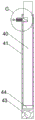
FIG. 4 is a schematic view of the internal structure of the junction box of the present invention;
FIG. 5 is a side view of the second support plate of the present invention;
FIG. 6 is a top view of the third working box of the present invention;
fig. 7 is an enlarged view of the point C in fig. 4 according to the present invention.
In the figure: 1. a storage tank; 2. a first work box; 3. a first motor; 4. a first rotating rod; 5. a second rotating rod; 6. a first bevel gear; 7. a second bevel gear; 8. a second work box; 9. a first screw rod; 10. A first sliding block; 11. a control panel; 12. a drawer; 13. a third work box; 14. a first connecting plate; 15. a second motor; 16. a reciprocating screw rod; 17. a third rotating rod; 18. a first gear; 19. a second sliding block; 20. a first rack; 21. a support plate; 22. a first support plate; 23. a display; 24. a second support plate; 25. a fourth rotating rod; 26. a second gear; 27. a cylinder; 28. a second rack; 29. a third support plate; 30. a support box; 31. a fourth work box; 32. a second connecting plate; 33. a pressing lever; 34. a first spring; 35. a connecting rod; 36. a first card slot; 37. a first clamping block; 38. a second card slot; 39. a second clamping block; 40. a baffle plate; 41. a connecting box; 42. a third connecting plate; 43. a fifth rotating rod; 44. a fourth connecting plate; 45. a fifth connecting plate; 46. a second spring; 47. a pull rod.
Detailed Description
The technical solutions in the embodiments of the present invention will be described clearly and completely with reference to the accompanying drawings in the embodiments of the present invention, and it is obvious that the described embodiments are only some embodiments of the present invention, not all embodiments. Based on the embodiments in the present invention, all other embodiments obtained by a person skilled in the art without creative work belong to the protection scope of the present invention.
Referring to fig. 1-7, the present invention provides a technical solution: a teaching device convenient for teacher-student interaction comprises a storage box 1, a first working box 2 is arranged inside the storage box 1, two second working boxes 8 are arranged at the top of the first working box 2, a first screw rod 9 is rotatably connected inside the second working box 8, a first slide block 10 is in threaded connection with the outer side of the first screw rod 9, the first slide block 10 is in sliding connection with the second working box 8, two second rotating rods 5 are rotatably connected inside the first working box 2, one end of each second rotating rod 5 is fixedly connected with the first screw rod 9, a support plate 21 is slidably connected between the two second working boxes 8, a third working box 13 at the top of the support plate 21, a reciprocating screw rod 16 is rotatably connected inside the third working box 13, a second motor 15 is arranged inside the third working box 13, the output end of the second motor 15 is fixedly connected with the reciprocating screw rod 16, a second slide block 19 is in threaded connection with the outer side of the reciprocating screw rod 16, and No. two sliders 19 and No. three workbenches 13 are slidably connected, one side of No. two sliders 19 is provided with a rack 20, the inside of No. three workbenches 13 is rotatably connected with No. three bull sticks 17, the outside of No. three bull sticks 17 is provided with a gear 18, the gear 18 is meshed with the rack 20 and is connected, the top of No. three workbenches 13 is rotatably connected with a connecting plate 14, one end of No. three bull sticks 17 is fixedly connected with the connecting plate 14, two drawers 12 are arranged inside the storage box 1, the inside of the storage box 1 is slidably connected with a support box 30, a reciprocating screw rod 16 conveniently drives No. two sliders 19 to move, No. two sliders 19 drive a rack 20 to move, the rack 20 drives No. three bull sticks 17 to rotate through the gear 18, and the rotating efficiency of No. one connecting plate 14 is improved.
One side of the first working box 2 is provided with a first motor 3, the inside of the first working box 2 is rotatably connected with a first rotating rod 4, the outer side of the first rotating rod 4 is provided with two first bevel gears 6, the outer side of the second rotating rod 5 is provided with a second bevel gear 7, the second bevel gear 7 is meshed with the first bevel gear 6 so that the first bevel gear 6 drives the second bevel gear 7 to rotate, the second bevel gear 7 drives a first screw rod 9 to rotate through the second rotating rod 5, the bottom of the supporting box 30 is provided with a fourth working box 31, the inside of the fourth working box 31 is symmetrically and slidably connected with a second connecting plate 32, the second connecting plate 32 is slidably connected with the supporting box 30, a first spring 34 is fixedly connected between the two second connecting plates 32, one side of the second connecting plate 32 is provided with a pressing rod 33, the pressing rod 33 is slidably connected with the fourth working box 31, one side of the second connecting plate 32 is provided with a connecting rod 35 positioned inside the supporting box 30, the connecting rod 35 is connected with the supporting box 30 in a sliding mode, one end of the connecting rod 35 is provided with a first clamping block 37, the first clamping block 37 is connected with the supporting box 30 in a sliding mode, first clamping grooves 36 matched with the first clamping block 37 are symmetrically formed in the storage box 1, the first clamping grooves 36 can fix the first clamping block 37 conveniently, the stability of the supporting box 30 is improved, the top of the first connecting plate 14 is fixedly connected with a second support plate 24, one side of the second support plate 24 is rotatably connected with a fourth rotating rod 25, the outer side of the fourth rotating rod 25 is provided with a second gear 26, one side of the second support plate 24 is provided with a third support plate 29, the top of the third support plate 29 is provided with an air cylinder 27, the output end of the air cylinder 27 is fixedly connected with a second rack 28, the second rack 28 is connected with the third support plate 29 in a sliding mode, the second gear 26 is connected with the second rack 28 in a meshing mode, one end of the fourth rotating rod 25 is fixedly connected with the display 23, the top of the first connecting plate 14 is fixedly connected with a first support plate 22, the display 23 is rotatably connected with the first support plate 22 through a rotating shaft, a second rack 28 drives a second gear 26 to rotate, the second gear 26 drives the display 23 to rotate through a fourth rotating rod 25, the display efficiency of the display 23 is improved, one side of the storage box 1 is provided with a third connecting plate 42, one side of the third connecting plate 42 is rotatably connected with a connecting box 41 through a fifth rotating rod 43, the inside of the connecting box 41 is slidably connected with a baffle 40, one side of the baffle 40 is provided with a fourth connecting plate 44, the fourth connecting plate 44 is slidably connected with the connecting box 41, one side of the connecting box 41 is provided with a fixed box, the inside of the fixed box is slidably connected with a fifth connecting plate 45, one side of the fifth connecting plate 45 is provided with a second clamping block 39, one side of the fifth connecting plate 45, which is far away from the second clamping block 39, is provided with a pull rod 47, the outside of the pull rod 47 is sleeved with a second spring 46, no. two draw-in grooves 38 with No. two fixture block 39 complex are seted up to one side of baffle 40, and No. two draw-in grooves 38 of being convenient for are fixed No. two fixture block 39, have improved the fixed stability of baffle 40, and one side of bin 1 is equipped with control panel 11, and a motor 3, No. two motor 15, display 23 and cylinder 27 all with control panel 11 electric connection, the control panel 11 of being convenient for carries out centralized control, has improved the security performance and the work efficiency of device.
Specifically, when in use, the first motor 3 is started through the control panel 11, the first motor 3 drives the first rotating rod 4 to rotate, the first rotating rod 4 drives the first bevel gear 6 to rotate, the first bevel gear 6 drives the second rotating rod 5 to rotate through the second bevel gear 7, the second rotating rod 5 drives the first screw rod 9 to rotate, the first screw rod 9 drives the first slide block 10 to move, the first slide block 10 drives the support plate 21 to move to a proper position, the second motor 15 is started, the second motor 15 drives the reciprocating screw rod 16 to rotate, the reciprocating screw rod 16 drives the second slide block 19 to move, the second slide block 19 drives the first rack 20 to move, the first rack 20 drives the third rotating rod 17 to rotate through the first gear 18, the third rotating rod 17 drives the first connecting plate 14 to rotate in a reciprocating manner, the air cylinder 27 is started, the air cylinder 27 drives the second rack 28 to move, the second rack 28 drives the fourth rotating rod 25 through the second gear 26, the fourth rotating rod 25 drives the display 23 to rotate to a proper angle, materials required for teaching are placed in the drawer 12, the support box 30 is directly pulled upwards by lifting the position of the support box 30, the first clamping block 37 is forced to leave the first clamping groove 36, the support box 30 is adjusted to a proper position, the second connecting plate 32 is driven by the pressing rod 33 to press the first spring 34 by the pressing rod 33, the second connecting plate 32 drives the connecting rod 35 to move, the first clamping block 37 is driven by the connecting rod 35 to leave the first clamping groove 36, the position of the support box 30 can be adjusted downwards, after the use is finished, the display 23 is retracted into the storage box 1, the connecting box 41 is turned over, the pull rod 47 is pulled, the fifth connecting plate 45 is driven by the pull rod 47 to move, the second clamping block 39 is driven by the fifth connecting plate 45 to leave the second clamping groove 38, the baffle 40 can be pulled out, and the baffle 40 and the connecting box 41 protect the top of the device, and can also be used as a platform.
In the description of the present invention, it is to be understood that the terms "coaxial", "bottom", "one end", "top", "middle", "other end", "upper", "one side", "top", "inner", "front", "center", "both ends", and the like, indicate orientations or positional relationships based on the orientations or positional relationships shown in the drawings, and are only for convenience of description and simplicity of description, and do not indicate or imply that the device or element referred to must have a particular orientation, be constructed and operated in a particular orientation, and therefore, should not be construed as limiting the present invention.
Furthermore, the terms "first", "second", "third", "fourth" are used for descriptive purposes only and are not to be construed as indicating or implying a relative importance or implicitly indicating the number of technical features indicated, whereby the features defined as "first", "second", "third", "fourth" may explicitly or implicitly include at least one such feature.
In the present invention, unless otherwise expressly stated or limited, the terms "mounted," "disposed," "connected," "fixed," "screwed" and the like are to be construed broadly, e.g., as meaning fixedly connected, detachably connected, or integrally formed; can be mechanically or electrically connected; they may be directly connected or indirectly connected through an intermediate medium, and may be connected through the inside of two elements or in an interaction relationship between two elements, unless otherwise specifically defined, and the specific meaning of the above terms in the present invention will be understood by those skilled in the art according to specific situations.
Although embodiments of the present invention have been shown and described, it will be appreciated by those skilled in the art that changes, modifications, substitutions and alterations can be made in these embodiments without departing from the principles and spirit of the invention, the scope of which is defined in the appended claims and their equivalents.
Claims (6)
1. The utility model provides a teaching device convenient to teacher and student are interactive, includes bin (1), its characterized in that, the inside of bin (1) is equipped with work box (2) No. one, the top of work box (2) is equipped with two work boxes (8) No. two, the inside rotation of No. two work boxes (8) is connected with lift lead screw (9), the outside threaded connection of lift lead screw (9) has slider (10) No. one, and slider (10) and work box (8) sliding connection No. two, the inside rotation of work box (2) is connected with two bull sticks (5) No. two, and the one end and the lift lead screw (9) fixed connection of bull stick (5) No. two sliding connection has backup pad (21) between work box (8), the top of backup pad (21) is equipped with work box (13) No. three, the inside rotation of work box (13) is connected with reciprocal lead screw (16), the inside of No. three work box (13) is equipped with No. two motor (15), and the output and the reciprocal lead screw (16) fixed connection of No. two motor (15), the outside threaded connection of reciprocal lead screw (16) has No. two slider (19), and No. two slider (19) and No. three work box (13) sliding connection, one side of No. two slider (19) is equipped with a rack (20), the inside rotation of No. three work box (13) is connected with No. three bull stick (17), the outside of No. three bull stick (17) is equipped with a gear (18), and a gear (18) and a rack (20) meshing connection, the top of No. three work box (13) is rotated and is connected with connecting plate (14), and the one end and connecting plate (14) fixed connection of No. three bull stick (17), the inside of bin (1) is equipped with two drawers (12), the inside of the storage box (1) is connected with a supporting box (30) in a sliding way.
2. The teaching device convenient for teacher-student interaction according to claim 1, wherein: one side of a work box (2) is equipped with motor (3) No. one, the internal rotation of a work box (2) is connected with bull stick (4) No. one, the outside of bull stick (4) is equipped with two bevel gear (6) No. one, the outside of No. two bull stick (5) is equipped with bevel gear No. two (7), and bevel gear No. two (7) and bevel gear (6) meshing connection.
3. The teaching device convenient for teacher-student interaction according to claim 1, wherein: a fourth work box (31) is arranged at the bottom of the support box (30), a second connecting plate (32) is symmetrically and slidably connected inside the fourth work box (31), a second connecting plate (32) is connected with the supporting box (30) in a sliding way, a first spring (34) is fixedly connected between the two second connecting plates (32), one side of the second connecting plate (32) is provided with a pressing rod (33), the pressing rod (33) is connected with the fourth work box (31) in a sliding way, a connecting rod (35) is arranged at one side of the second connecting plate (32) and positioned in the supporting box (30), and the connecting rod (35) is connected with the supporting box (30) in a sliding way, one end of the connecting rod (35) is provided with a first clamping block (37), and a first clamping block (37) is slidably connected with the supporting box (30), and a first clamping groove (36) matched with the first clamping block (37) is symmetrically formed in the storage box (1).
4. The teaching device convenient for teacher-student interaction according to claim 2, wherein: a second support plate (24) is fixedly connected to the top of the first connecting plate (14), a fourth rotating rod (25) is rotatably connected to one side of the second support plate (24), a second gear (26) is arranged on the outer side of the fourth rotating rod (25), a third support plate (29) is arranged on one side of the second support plate (24), the top of the third support plate (29) is provided with an air cylinder (27), the output end of the air cylinder (27) is fixedly connected with a second rack (28), the second rack (28) is connected with the third support plate (29) in a sliding way, the second gear (26) is connected with the second rack (28) in a meshing way, one end of the fourth rotating rod (25) is fixedly connected with a display (23), the top of the first connecting plate (14) is fixedly connected with a first support plate (22), and the display (23) is rotationally connected with the first support plate (22) through a rotating shaft.
5. The teaching device convenient for teacher-student interaction according to claim 1, wherein: a third connecting plate (42) is arranged on one side of the storage box (1), one side of the third connecting plate (42) is rotatably connected with a connecting box (41) through a fifth rotating rod (43), a baffle plate (40) is connected inside the connecting box (41) in a sliding way, a fourth connecting plate (44) is arranged on one side of the baffle plate (40), and the fourth connecting plate (44) is connected with the connecting box (41) in a sliding way, one side of the connecting box (41) is provided with a fixed box, a fifth connecting plate (45) is slidably connected inside the fixed box, a second clamping block (39) is arranged on one side of the fifth connecting plate (45), a pull rod (47) is arranged on one side of the fifth connecting plate (45) far away from the second clamping block (39), a second spring (46) is sleeved outside the pull rod (47) and inside the fixed box, a second clamping groove (38) matched with the second clamping block (39) is formed in one side of the baffle (40).
6. The teaching device convenient for teacher-student interaction according to claim 4, wherein: one side of bin (1) is equipped with control panel (11), a motor (3), No. two motor (15), display (23) and cylinder (27) all with control panel (11) electric connection.
Priority Applications (1)
| Application Number | Priority Date | Filing Date | Title |
|---|---|---|---|
| CN202023063857.8U CN214175407U (en) | 2020-12-17 | 2020-12-17 | Teaching device convenient for teacher-student interaction |
Applications Claiming Priority (1)
| Application Number | Priority Date | Filing Date | Title |
|---|---|---|---|
| CN202023063857.8U CN214175407U (en) | 2020-12-17 | 2020-12-17 | Teaching device convenient for teacher-student interaction |
Publications (1)
| Publication Number | Publication Date |
|---|---|
| CN214175407U true CN214175407U (en) | 2021-09-10 |
Family
ID=77607083
Family Applications (1)
| Application Number | Title | Priority Date | Filing Date |
|---|---|---|---|
| CN202023063857.8U Active CN214175407U (en) | 2020-12-17 | 2020-12-17 | Teaching device convenient for teacher-student interaction |
Country Status (1)
| Country | Link |
|---|---|
| CN (1) | CN214175407U (en) |
Cited By (2)
| Publication number | Priority date | Publication date | Assignee | Title |
|---|---|---|---|---|
| CN114081272A (en) * | 2021-11-12 | 2022-02-25 | 南京审计大学 | Lifting platform with big data retrieval function for computer and using method thereof |
| CN115723955A (en) * | 2022-11-17 | 2023-03-03 | 中国民用航空飞行学院 | Fixing device for electronic equipment of civil aircraft |
-
2020
- 2020-12-17 CN CN202023063857.8U patent/CN214175407U/en active Active
Cited By (4)
| Publication number | Priority date | Publication date | Assignee | Title |
|---|---|---|---|---|
| CN114081272A (en) * | 2021-11-12 | 2022-02-25 | 南京审计大学 | Lifting platform with big data retrieval function for computer and using method thereof |
| CN114081272B (en) * | 2021-11-12 | 2023-02-24 | 南京审计大学 | Lifting platform with big data retrieval function for computer and using method thereof |
| CN115723955A (en) * | 2022-11-17 | 2023-03-03 | 中国民用航空飞行学院 | Fixing device for electronic equipment of civil aircraft |
| CN115723955B (en) * | 2022-11-17 | 2024-04-19 | 中国民用航空飞行学院 | Fixing device for civil aircraft electronic equipment |
Similar Documents
| Publication | Publication Date | Title |
|---|---|---|
| CN214175407U (en) | Teaching device convenient for teacher-student interaction | |
| CN211511239U (en) | Biological specimen show shelf is used in teaching | |
| CN210256064U (en) | Toolbox is used in nursing teaching | |
| CN216412602U (en) | Supplementary recruitment selection device | |
| CN208512595U (en) | A kind of student convenient for adjusting learns with physical test platform | |
| CN213815033U (en) | Display device that legal case analysis was used | |
| CN214127850U (en) | Consultation display device for technical consultation | |
| CN212208582U (en) | Computer network teaching experimental equipment | |
| CN212990431U (en) | Vocabulary simulation training device for english teaching | |
| CN211827664U (en) | Real standard platform of thing networking education | |
| CN208627370U (en) | A kind of paediatrics test tube for blood test frame | |
| CN111227508A (en) | Novel experimental apparatus of education technique | |
| CN219202565U (en) | Display device | |
| CN219162921U (en) | Height-adjustable information display stand | |
| CN216268384U (en) | Geometric drawing board for high school mathematics students | |
| CN214796531U (en) | Think political affairs knowledge propaganda device that political affairs was used | |
| CN212415108U (en) | Adjustable office table for office work | |
| CN215721796U (en) | Intelligent psychological occupational assessment device | |
| CN211706861U (en) | High school physics is with multi-functional laboratory bench | |
| CN214855240U (en) | Novel multi-functional electronic information technology specialty is synthesized and is instructed real teaching device | |
| CN214346590U (en) | Multifunctional electrical engineering experiment table | |
| CN214127573U (en) | Furniture cabinet convenient to install | |
| CN218923148U (en) | Muscle relaxing device | |
| CN213042517U (en) | New energy automobile charging system teaching is with show shelf | |
| CN215532689U (en) | A intelligent storing device for space optimization |
Legal Events
| Date | Code | Title | Description |
|---|---|---|---|
| GR01 | Patent grant | ||
| GR01 | Patent grant |