CN214170796U - Steady voltage pump installation component and purifier - Google Patents
Steady voltage pump installation component and purifier Download PDFInfo
- Publication number
- CN214170796U CN214170796U CN202023207186.8U CN202023207186U CN214170796U CN 214170796 U CN214170796 U CN 214170796U CN 202023207186 U CN202023207186 U CN 202023207186U CN 214170796 U CN214170796 U CN 214170796U
- Authority
- CN
- China
- Prior art keywords
- pump
- bracket
- damping pad
- mounting
- mounting bracket
- Prior art date
- Legal status (The legal status is an assumption and is not a legal conclusion. Google has not performed a legal analysis and makes no representation as to the accuracy of the status listed.)
- Active
Links
Images


Landscapes
- Structures Of Non-Positive Displacement Pumps (AREA)
Abstract
The utility model relates to a purifier technical field, concretely relates to steady voltage pump installation component and purifier, steady voltage pump installation component, include: a whole machine bracket; the cover casing is suitable for covering the whole machine bracket; the mounting bracket is fixedly arranged in the whole machine bracket and the housing and is provided with a mounting cavity suitable for mounting a pressure stabilizing pump; the pressure stabilizing pump is fixedly arranged in the mounting bracket; a first damping pad is arranged between the mounting bracket and the pressure stabilizing pump, and a second damping pad is arranged between the mounting bracket and the whole machine bracket and between the mounting bracket and the housing. The pressure stabilizing pump and the mounting bracket are elastically connected with the whole machine bracket, and when the pressure stabilizing pump works, vibration generated by the pressure stabilizing pump is firstly eliminated through the first vibration damping pad for the first time, and then is further absorbed through the mounting bracket and the second vibration damping pad, so that the vibration can not be transmitted to the whole machine bracket, the generation of the vibration and the noise of the whole machine is avoided, and the use feeling of a user can be improved.
Description
Technical Field
The utility model relates to a purifier technical field, concretely relates to steady voltage pump installation component and purifier.
Background
With the rapid development of the water purification industry, the reverse osmosis water purifier gradually becomes the main development direction of the market. The surge damping pump is as the important component part of reverse osmosis water purification machine, and it has great vibration at the during operation, and the noise that produces is great, seriously influences user's use and feels.
SUMMERY OF THE UTILITY MODEL
Therefore, the to-be-solved technical problem of the utility model lies in overcoming the steady voltage pump during operation vibration among the prior art, the great defect of noise to a steady voltage pump installation component and purifier that can reduce vibration and fall make an uproar are provided.
In order to solve the technical problem, the utility model provides a pair of steady voltage pump installation component, include:
a whole machine bracket;
the cover casing is suitable for covering the whole machine bracket;
the mounting bracket is fixedly arranged in the whole machine bracket and the housing and is provided with a mounting cavity suitable for mounting a pressure stabilizing pump;
the pressure stabilizing pump is fixedly arranged in the mounting bracket;
a first damping pad is arranged between the mounting bracket and the pressure stabilizing pump, and a second damping pad is arranged between the mounting bracket and the whole machine bracket and between the mounting bracket and the housing.
Optionally, two water pipes of the pressure stabilizing pump respectively penetrate through the whole machine bracket and the housing, and a third damping pad is arranged between the water pipes and the whole machine bracket and between the water pipes and the housing.
Optionally, the third damping pad is disposed on the water pipe and connected with the water pipe in an interference fit manner.
Optionally, the third vibration damping pad is connected with the complete machine bracket and the housing in an interference fit manner.
Optionally, a flexible sleeve is arranged on the water pipe.
Optionally, the tail end of the pressure stabilizing pump is provided with sound absorbing cotton.
Optionally, two sides of the pressure stabilizing pump and the mounting bracket are respectively connected through a bolt assembly, and a bolt is suitable for penetrating through the first damping pad.
Optionally, the bolt assembly comprises a nut pre-fixed on the mounting bracket, and the bolt penetrates through the mounting bracket, the pressure stabilizing pump and the first damping pad.
Optionally, a nut fixing position is arranged on the mounting bracket, and the nut is connected with the nut fixing position in an interference fit manner.
Optionally, a gap is provided between the first damping pad and the mounting bracket.
Optionally, the pressure stabilizing pump comprises a pump body and a support plate fixedly mounted on the pump body, the first vibration damping pad is arranged on the support plate and penetrates through the support plate, and a gap is formed between the upper end of the first vibration damping pad and the mounting bracket.
Optionally, the mounting bracket is connected with the second vibration damping pad in an interference fit manner.
Optionally, the complete machine bracket is connected with the housing through a buckle.
Optionally, the complete machine bracket is further connected with the housing through screws.
The utility model also provides a water purifier, include steady voltage pump installation component.
The utility model discloses technical scheme has following advantage:
1. the utility model provides a steady voltage pump installation component is elastic connection between steady voltage pump and installing support, installing support and the complete machine support, and steady voltage pump during operation, the vibration of its production at first can carry out first elimination through first damping pad, secondly further absorbs through installing support and second damping pad for the complete machine support can not be given in the vibration transmission, thereby avoids the production of complete machine vibration and noise, can promote the user and use the impression.
2. The utility model provides a steady voltage pump installation component, two water pipes of steady voltage pump wear to establish respectively the complete machine support the housing, the water pipe with the complete machine support be provided with the third damping pad between the housing, the setting up of third damping pad makes steady voltage pump during operation, can reduce the vibration of water pipe, avoids water pipe and complete machine support, housing because the collision produces the noise, has further played the effect of making an uproar that falls in the damping.
3. The utility model provides a steady voltage pump installation component, the tail end of steady voltage pump is equipped with inhales the sound cotton, inhales the sound cotton and can absorb the mechanical noise that steady voltage pump internal work produced.
Drawings
In order to more clearly illustrate the embodiments of the present invention or the technical solutions in the prior art, the drawings used in the embodiments or the technical solutions in the prior art will be briefly described below, and it is obvious that the drawings in the following description are some embodiments of the present invention, and for those skilled in the art, other drawings can be obtained according to these drawings without creative efforts.
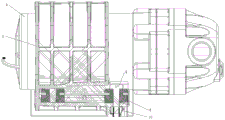
Fig. 1 is an exploded view of a stabilized pressure pump mounting assembly provided in embodiment 1 of the present invention;
fig. 2 is a top view of a stabilized pressure pump mounting assembly provided in embodiment 1 of the present invention;
FIG. 3 is a cross-sectional view A-A of FIG. 2;
FIG. 4 is a schematic diagram of the surge tank of FIG. 1;
FIG. 5 is a schematic structural view of the mounting bracket of FIG. 1;
FIG. 6 is a schematic view of the assembled mounting bracket and stabilized pressure pump of FIG. 1;
FIG. 7 is a top view of FIG. 6;
FIG. 8 is a cross-sectional view B-B of FIG. 7;
fig. 9 is a schematic structural view of a support plate of the pressure maintaining pump in fig. 4.
Description of reference numerals:
1-a complete machine bracket; 2, mounting a bracket; 21-fixing the nut; 22-a mounting cavity; 3-a housing; 4-a pressure stabilizing pump; 41-water pipe; 42-a pump body; 43-a support plate; 5-a first damping pad; 6-a second damping pad; 7-a third damping pad; 8-sound absorbing cotton; 9-bolt; 10-a nut; 11-a screw; 12-flexible sheath.
Detailed Description
The technical solution of the present invention will be described clearly and completely with reference to the accompanying drawings, and obviously, the described embodiments are some, but not all embodiments of the present invention. Based on the embodiments in the present invention, all other embodiments obtained by a person skilled in the art without creative work belong to the protection scope of the present invention.
In the description of the present invention, it should be noted that the terms "center", "upper", "lower", "left", "right", "vertical", "horizontal", "inner", "outer", and the like indicate orientations or positional relationships based on the orientations or positional relationships shown in the drawings, and are only for convenience of description and simplification of description, but do not indicate or imply that the device or element referred to must have a specific orientation, be constructed and operated in a specific orientation, and thus, should not be construed as limiting the present invention. Furthermore, the terms "first," "second," and "third" are used for descriptive purposes only and are not to be construed as indicating or implying relative importance.
In the description of the present invention, it is to be noted that, unless otherwise explicitly specified or limited, the terms "mounted," "connected," and "connected" are to be construed broadly, and may be, for example, fixedly connected, detachably connected, or integrally connected; can be mechanically or electrically connected; they may be connected directly or indirectly through intervening media, or they may be interconnected between two elements. The specific meaning of the above terms in the present invention can be understood in specific cases to those skilled in the art.
Furthermore, the technical features mentioned in the different embodiments of the invention described below can be combined with each other as long as they do not conflict with each other.
Example 1
With the rapid development of the water purification industry, the reverse osmosis water purifier gradually becomes the main development direction of the market. The surge damping pump is as the important component part of reverse osmosis water purification machine, and it has great vibration at the during operation, and the noise that produces is great, seriously influences user's use and feels.
To this end, the present embodiment provides a surge tank mounting assembly, which in one embodiment, as shown in fig. 1 to 9, includes a complete machine bracket 1, a housing 3, a mounting bracket 2, and a surge tank 4.
The whole machine bracket 1 can be used for fixedly mounting other parts of the water purifier; the cover 3 is suitable for covering the whole machine bracket 1; the mounting bracket 2 is fixedly arranged in the whole machine bracket 1 and the housing 3 and is provided with a mounting cavity 22 suitable for mounting the pressure stabilizing pump 4; the pressure stabilizing pump 4 is fixedly arranged in the mounting bracket 2; a first damping pad 5 is arranged between the mounting bracket 2 and the pressure stabilizing pump 4, and a second damping pad 6 is arranged between the mounting bracket 2 and the complete machine bracket 1 and the housing 3.
According to the pressure stabilizing pump mounting assembly provided by the embodiment, the pressure stabilizing pump 4 is elastically connected with the mounting bracket 2 and the mounting bracket 2 is elastically connected with the whole machine bracket 1, and when the pressure stabilizing pump 4 works, vibration generated by the pressure stabilizing pump is firstly eliminated through the first vibration damping pad 5, and then is further absorbed through the mounting bracket 2 and the second vibration damping pad 6, so that the vibration can not be transmitted to the whole machine bracket 1, the generation of the vibration and the noise of the whole machine is avoided, and the use feeling of a user can be improved.
In addition to the above embodiments, in a preferred embodiment, two water pipes 41 of the pressure stabilizing pump 4 are respectively inserted into the complete machine bracket 1 and the housing 3, and a third damping pad 7 is arranged between the water pipes 41 and the complete machine bracket 1 and the housing 3. Specifically, the mounting through holes are respectively formed in the complete machine support 1 and the housing 3, the two water pipes 41 respectively penetrate through the mounting through holes, the third vibration damping pad 7 is arranged at the mounting through holes, and the third vibration damping pad is arranged to reduce the vibration of the water pipes 41 when the pressure stabilizing pump 4 works, so that the water pipes 41 are prevented from generating noise due to collision with the complete machine support 1 and the housing 3, and the effects of vibration damping and noise reduction are further achieved.
On the basis of the above embodiment, in a preferred embodiment, the third vibration damping pad is arranged on the water pipe 41 and connected with the water pipe 41 in an interference fit manner, specifically, the third vibration damping pad 7 has a central hole, the hole diameter of the central hole is slightly smaller than the outer diameter of the water pipe 41, the third vibration damping pad 7 is sleeved outside the water pipe 41, and in this embodiment, when the surge damping pump 4 works, the third vibration damping pad 7 can reduce the vibration of the water pipe 41.
In addition to the above embodiments, in a preferred embodiment, the third vibration damping pad is connected to the complete machine bracket 1 and the housing 3 by interference fit. Specifically, the third damping pad 7 is annular, and the outer diameter of the third damping pad is slightly larger than the aperture of the mounting through hole in the complete machine support 1 and the housing 3, so that in the embodiment, the third damping pad 7 can be further prevented from being separated from the mounting through hole, the water pipe 41 is prevented from colliding with the complete machine support 1 and the housing 3, and the damping and noise reduction effects are ensured.
In addition to the above embodiments, in one embodiment, the water pipe 41 is provided with the flexible sheath 12. The flexible sleeve 12 can further dampen vibration and reduce noise. Specifically, the water pipe 41 is wrapped by a flexible sleeve 12, and the flexible sleeve 12 can be a sponge sleeve, a rubber sleeve and the like.
In addition to the above embodiments, in one embodiment, the tail end of the pressure stabilizing pump 4 is provided with sound absorbing cotton 8. Specifically, the end of the pressure stabilizing pump 4 connected with the water pipe 41 is the front end, the end of the pressure stabilizing pump 4 connected with the power line is the tail end, after the pressure stabilizing pump 4 is installed, the sound absorbing cotton 8 is located between the tail end of the pressure stabilizing pump 4 and the whole machine support 1, and the sound absorbing cotton 8 can absorb mechanical noise generated in the pressure stabilizing pump 4 during working.
In particular, in one embodiment, the sound-absorbing cotton 8 is composed of bicomponent cotton, centrifugal glass cotton, or the like.
On the basis of the above embodiment, in a preferred embodiment, both sides of the surge pump 4 and the mounting bracket 2 are respectively connected by bolt assemblies, and the bolts 9 are adapted to pass through the first damping pad. In the embodiment, the pressure stabilizing pump 4 and the mounting bracket 2 only need to be connected through two groups of bolt assemblies, and compared with the prior art that four bolts are needed for fixing the pressure stabilizing pump 4, the cost can be reduced to a certain extent. Meanwhile, bolt holes suitable for bolts 9 to penetrate are formed in the first vibration damping pads, the bolts 9 penetrate through the first vibration damping pads 5, the pressure stabilizing pump 4 and the mounting bracket 2 can be fixed, and the first vibration damping pads can be fixed, so that the pressure stabilizing pump 4 and the mounting bracket 2 are firmly and reliably connected.
Specifically, the bolt assembly comprises a nut 10 which is fixed on the mounting bracket 2 in advance, and a bolt 9 which penetrates through the mounting bracket 2, the pressure stabilizing pump 4 and the first damping pad. In the embodiment, as the nut 10 is fixed on the mounting bracket 2 in advance, when the bolt 9 is connected, the bolt 9 only needs to be screwed after penetrating the pressure stabilizing pump 4, the first damping pad 5 and the mounting bracket 2, and the connection mode is simplified. Specifically, in one embodiment, the surge damping pump 4 comprises a pump body 42 and a support plate 43 fixedly mounted on the pump body 42 through screws, wherein first damping pads are arranged on the support plate 43 and penetrate through the support plate 43, when the surge damping pump is mounted, the support plate 43 is fixedly connected to the pump body 42 through screws, then four first damping pads 5 respectively penetrate through the support plate 43, at the moment, the surge damping pump 4 is placed on the mounting bracket 2 fixed with the nut 10 in advance, and after the surge damping pump 4 is mounted in place in the mounting cavity 22, the surge damping pump 4 is connected with the mounting bracket 2 through the bolt holes in the first damping pads 5 located outside the mounting cavity by using bolts 9. Of course, in other alternative embodiments, the support plate 43 may be connected to the pump body 42 by welding.
In a preferred embodiment, the mounting bracket 2 is provided with a nut fixing position 21, and the nut 10 is connected with the nut fixing position 21 in an interference fit manner. In this embodiment, it is ensured that the nut 10 does not easily fall off or become loose when it is placed beforehand.
In addition to the above embodiments, in a preferred embodiment, a gap is provided between the first cushion and the mounting bracket 2. In this embodiment, the first vibration damping pad can be fixed vertically, and the gap provided for allows the first vibration damping pad to have a certain vibration space.
Specifically, in one embodiment, the surge tank 4 includes a pump body 42, a support plate 43 fixedly mounted on the pump body 42 by screws, a first damping pad is disposed on the support plate 43 and penetrates through the support plate 43, and a gap is provided between the upper end of the first damping pad 5 and the mounting bracket 2. Specifically, the gap value may be 0.3 to 0.5 mm. In an alternative embodiment, a gap may be provided between the lower end of the first damping pad and the mounting bracket 2.
In addition to the above embodiments, in a preferred embodiment, the mounting bracket 2 is connected with the second vibration damping pad in an interference fit manner. As shown in fig. 3, the second vibration damping pad is pre-arranged on the complete machine support 1 and the housing 3, when being installed, the mounting support 2 is inserted into the second vibration damping pad 6, specifically, the lengths of the upper end and the lower end of the mounting support 2 are slightly larger than the length of the second vibration damping pad 6, so that the mounting support 2 and the second vibration damping pad are connected in an interference fit manner, the mounting support 2 can be prevented from being separated from the second vibration damping pad 6, and vibration is reduced as much as possible.
On the basis of the above embodiments, in a preferred embodiment, the whole machine bracket 1 and the housing 3 are connected by a snap. The connection mode of the whole machine bracket 1 and the housing 3 is simple and convenient.
In one embodiment, the whole machine support 1 is connected with the housing 3 through the screws 11, and the whole machine support 1 is connected with the housing 3 through the snap connection and the screws 11, so that the connection mode can be simplified, the number of the screws can be reduced, and the connection reliability can be ensured.
According to the pressure stabilizing pump mounting assembly provided by the embodiment, the pressure stabilizing pump 4 is elastically connected with the mounting bracket 2 and the mounting bracket 2 is elastically connected with the whole machine bracket 1, and when the pressure stabilizing pump 4 works, vibration generated by the pressure stabilizing pump is firstly eliminated through the first vibration damping pad, and then is further absorbed through the mounting bracket 2 and the second vibration damping pad 6, so that the vibration can not be transmitted to the whole machine bracket 1, and the generation of the vibration and the noise of the whole machine is avoided. The tail end of the pressure stabilizing pump 4 is provided with sound absorbing cotton 8 which can absorb mechanical noise generated by the internal work of the pressure stabilizing pump 4; the third vibration reduction pad is arranged between the water inlet pipe and the water outlet pipe of the two water pipes 41, the water outlet pipe, the whole machine support 1 and the housing 3, vibration of the water pipes 41 can be reduced, noise generated by collision with the whole machine support 1 is avoided, and the sponge sleeve wraps the water pipes 41 and can reduce vibration and noise again.
The pressure stabilizing pump mounting assembly provided by the embodiment has the advantages of simple structure and reasonable design, and experimental test data show that the pressure stabilizing pump mounting assembly can effectively reduce 5-8 dba, has obvious vibration reduction effect, effectively improves tone quality and improves user experience.
Example 2
The embodiment provides a water purifier, which comprises the pressure stabilizing pump mounting assembly provided in the embodiment.
It should be understood that the above examples are only for clarity of illustration and are not intended to limit the embodiments. Other variations and modifications will be apparent to persons skilled in the art in light of the above description. And are neither required nor exhaustive of all embodiments. And obvious variations or modifications can be made without departing from the scope of the invention.
Claims (15)
1. A stabilized pressure pump mounting assembly, comprising:
a complete machine bracket (1);
the cover casing (3) is suitable for covering the whole machine bracket (1);
the mounting bracket (2) is fixedly arranged in the whole machine bracket (1) and the housing (3) and is provided with a mounting cavity (22) suitable for mounting a pressure stabilizing pump (4);
the pressure stabilizing pump (4) is fixedly arranged in the mounting bracket (2);
a first damping pad (5) is arranged between the mounting bracket (2) and the pressure stabilizing pump (4), and a second damping pad (6) is arranged between the mounting bracket (2) and the whole machine bracket (1) and between the housing (3).
2. A pressure stabilizing pump mounting assembly according to claim 1, wherein two water pipes (41) of the pressure stabilizing pump (4) are respectively arranged through the whole machine bracket (1) and the housing (3), and a third damping pad (7) is arranged between the water pipes (41) and the whole machine bracket (1) and the housing (3).
3. A stabilivolt pump mounting assembly as claimed in claim 2, wherein said third damping pad (7) is provided on said water tube (41) and is in interference fit connection with said water tube (41).
4. A stabilized pressure pump mounting assembly according to claim 3, wherein the third damping pad (7) is connected with the complete machine bracket (1) and the housing (3) in an interference fit manner respectively.
5. A stabilized pump mounting assembly according to claim 2, wherein a flexible sleeve (12) is provided on the water tube (41).
6. A stabilized pressure pump mounting assembly according to claim 1, characterized in that the tail end of the stabilized pressure pump (4) is provided with sound absorbing cotton (8).
7. A pump mounting assembly according to any one of claims 1-6, wherein both sides of the pump (4) are connected to the mounting bracket (2) by respective bolt assemblies, and bolts (9) are adapted to pass through the first damping pads (5).
8. A stabilivolt pump mounting assembly as claimed in claim 7, characterized in that said bolt assembly comprises a nut (10) pre-fixed to said mounting bracket (2) and said bolt (9) passing through said mounting bracket (2), said stabilivolt pump (4), said first damping pad (5).
9. A mounting assembly for a pressure maintaining pump according to claim 8, wherein the mounting bracket (2) is provided with a nut fixing position (21), and the nut (10) is connected with the nut fixing position (21) in an interference fit manner.
10. A stabilized pump mounting assembly according to claim 7, wherein a gap is provided between the first damping pad (5) and the mounting bracket (2).
11. A stabilivolt pump mounting assembly according to claim 10, characterized in that the stabilivolt pump (4) comprises a pump body (42), a support plate (43) fixedly mounted on the pump body, the first damping pad (5) being provided on the support plate (43) and extending through the support plate (43), a gap being provided between an upper end of the first damping pad (5) and the mounting bracket (2).
12. A stabilized pump mounting assembly according to any one of claims 1-6, wherein the mounting bracket (2) is connected with the second damping pad (6) in an interference fit.
13. A stabilized pressure pump mounting assembly according to any one of claims 1-6, characterized in that the complete machine bracket (1) and the casing (3) are connected by a snap fit.
14. A stabilized pump mounting assembly according to claim 13, wherein the complete machine bracket (1) and the casing (3) are further connected by screws (11).
15. A water purifier comprising the stabilized pressure pump mounting assembly of any one of claims 1-14.
Priority Applications (1)
| Application Number | Priority Date | Filing Date | Title |
|---|---|---|---|
| CN202023207186.8U CN214170796U (en) | 2020-12-25 | 2020-12-25 | Steady voltage pump installation component and purifier |
Applications Claiming Priority (1)
| Application Number | Priority Date | Filing Date | Title |
|---|---|---|---|
| CN202023207186.8U CN214170796U (en) | 2020-12-25 | 2020-12-25 | Steady voltage pump installation component and purifier |
Publications (1)
| Publication Number | Publication Date |
|---|---|
| CN214170796U true CN214170796U (en) | 2021-09-10 |
Family
ID=77609465
Family Applications (1)
| Application Number | Title | Priority Date | Filing Date |
|---|---|---|---|
| CN202023207186.8U Active CN214170796U (en) | 2020-12-25 | 2020-12-25 | Steady voltage pump installation component and purifier |
Country Status (1)
| Country | Link |
|---|---|
| CN (1) | CN214170796U (en) |
Cited By (1)
| Publication number | Priority date | Publication date | Assignee | Title |
|---|---|---|---|---|
| CN114412775A (en) * | 2022-01-24 | 2022-04-29 | 珠海格力电器股份有限公司 | Pump body structure and water purification unit |
-
2020
- 2020-12-25 CN CN202023207186.8U patent/CN214170796U/en active Active
Cited By (2)
| Publication number | Priority date | Publication date | Assignee | Title |
|---|---|---|---|---|
| CN114412775A (en) * | 2022-01-24 | 2022-04-29 | 珠海格力电器股份有限公司 | Pump body structure and water purification unit |
| CN114412775B (en) * | 2022-01-24 | 2023-09-05 | 珠海格力电器股份有限公司 | Pump body structure and water purification equipment |
Similar Documents
| Publication | Publication Date | Title |
|---|---|---|
| CN214170796U (en) | Steady voltage pump installation component and purifier | |
| JP2008215306A (en) | Fuel supply device | |
| CN210171234U (en) | Water purifying equipment | |
| CN210106139U (en) | A silence structure and reverse osmosis water purification machine for booster pump | |
| CN214616927U (en) | Noise-reducing and shock-absorbing compressor assembly for oxygenerator | |
| CN210141190U (en) | Integrated pump | |
| CN214693351U (en) | Water purifier with function of making an uproar is fallen | |
| CN218669934U (en) | Shock attenuation amortization shell and self priming pump | |
| CN217056150U (en) | Oil pump clamping damping mechanism | |
| CN219809187U (en) | Shock attenuation structure of making an uproar falls in booster pump and clean drinking equipment | |
| CN218542589U (en) | Pump mounting structure and purifier | |
| CN215072821U (en) | Loudspeaker subassembly and intelligent interaction equipment | |
| CN210565368U (en) | Filter pump and shockproof structure thereof | |
| CN218669748U (en) | Multifunctional water purifier shock attenuation mesochite | |
| CN216591869U (en) | Range hood with volute vibration damping structure | |
| CN216975202U (en) | Noise reduction device and water purification device | |
| CN216741957U (en) | Water pump assembly and water treatment equipment | |
| CN219366395U (en) | Silencing box, booster pump assembly and purifier of booster pump | |
| CN221005447U (en) | Air purifier with motor shock-absorbing structure | |
| CN209067498U (en) | Water purifier and booster pump assembly thereof | |
| CN218062642U (en) | Water purifier and booster pump assembly thereof | |
| CN219812037U (en) | Motor bearing cap assembly | |
| CN218088983U (en) | Water purifying equipment | |
| CN214533486U (en) | Device of making an uproar falls in spring | |
| CN211209422U (en) | Connecting end cover for three-phase asynchronous motor |
Legal Events
| Date | Code | Title | Description |
|---|---|---|---|
| GR01 | Patent grant | ||
| GR01 | Patent grant |