CN214121504U - Rotation type leak hunting device - Google Patents
Rotation type leak hunting device Download PDFInfo
- Publication number
- CN214121504U CN214121504U CN202022189575.6U CN202022189575U CN214121504U CN 214121504 U CN214121504 U CN 214121504U CN 202022189575 U CN202022189575 U CN 202022189575U CN 214121504 U CN214121504 U CN 214121504U
- Authority
- CN
- China
- Prior art keywords
- cylinder
- water tank
- box body
- main box
- rotating shaft
- Prior art date
- Legal status (The legal status is an assumption and is not a legal conclusion. Google has not performed a legal analysis and makes no representation as to the accuracy of the status listed.)
- Active
Links
Images


Abstract
The utility model discloses a rotation type leak hunting device, including leaking main tank body, water tank, conveyer, telescopic cylinder, the conveyer inboard is provided with leak hunting main tank body, leak hunting main tank body downside is provided with the water tank, the water tank lower extreme passes through the water tank elevating platform and connects the conveyer, leak hunting main tank body power end is connected with leak hunting main tank body both ends rotation axis, leak hunting main tank body both ends rotation axis passes through the bearing frame and connects the conveyer. The utility model discloses utilize the clamp motor to drive the rotatory holder that drives of hollow rotation axis for motor driven sprocket and reach and screw up the jar, it is flexible to utilize telescopic cylinder to drive the rotation axis simultaneously to compress tightly the jar, improve leakproofness and work efficiency, utilize water tank elevating platform to drive the water tank and go up and down, utilize simultaneously to leak hunting main tank body on be provided with two side holders, utilize 180 degrees revolving cylinder to overturn simultaneously, can carry out seamless switching detection, improve work efficiency.
Description
Technical Field
The utility model relates to a leak hunting field especially relates to a rotation type leak hunting device.
Background
The jar body needs to detect the sealed degree of the jar body in the course of working to can reach the requirement of encapsulation, just can guarantee the security and the leakproofness of inside splendid attire material.
Generally when carrying out the seal detection to the jar body, all utilize the leak hunting device, but general leak hunting device all is that the single rank is installed and is detected, and the centre has partly blank period, has wasted certain man-hour, and work efficiency is not high.
Disclosure of Invention
An object of the utility model is to provide a rotation type leak hunting device just in order to solve above-mentioned problem.
The utility model discloses a following technical scheme realizes above-mentioned purpose:
a rotary leak detection device comprises a leak detection main box body, a water tank, a transmission machine and a telescopic cylinder, wherein the leak detection main box body is arranged on the inner side of the transmission machine, the water tank is arranged on the lower side of the leak detection main box body, the lower end of the water tank is connected with the transmission machine through a water tank lifting platform, the power ends of the leak detection main box body are connected with rotating shafts at two ends of the leak detection main box body, the rotating shafts at two ends of the leak detection main box body are connected with the transmission machine through bearing seats, the power ends of the rotating shafts at two ends of the leak detection main box body are connected with a 180-degree rotating cylinder through a coupler, and the outer part of the 180-degree rotating cylinder is connected with the transmission machine through a rotating cylinder seat;
the outer end face of the leakage detection main box body is provided with the telescopic cylinder, the power end of the telescopic cylinder is provided with an aluminum sleeve for connecting a cylinder shaft through the outside of the cylinder shaft, the upper end of the cylinder shaft is provided with a rotating shaft, the outside of the rotating shaft is provided with a hollow rotating shaft for a motor driven sprocket, the aluminum sleeve for connecting the cylinder shaft is provided with a fixing screw, the upper side of the aluminum sleeve for connecting the cylinder shaft is provided with a rotating shaft lower flange, the upper side of the rotating shaft lower flange is provided with an aluminum sleeve for limiting the rotating shaft, the upper side of the aluminum sleeve for limiting the rotating shaft is provided with a pressing gasket, a double sprocket is connected to the outside of the hollow rotating shaft for the motor driven sprocket, the upper side of the double sprocket is provided with a motor driven sprocket, the motor driven sprocket is connected with the hollow rotating shaft for the motor driven sprocket through the fixing screw and the transmission, and the upper side of the motor driven sprocket is provided with a hollow rotating shaft limiting flange for the motor driven sprocket, the clamping seat is connected to the upper end of the rotating shaft, the motor driven chain wheel is connected with the clamping motor through a chain, and the two chain wheels are connected through the chain.
Preferably: the rotary cylinder seat is connected with the 180-degree rotary cylinder and the conveyor through bolts, and the coupler is connected with the 180-degree rotary cylinder and rotating shafts at two ends of the leak detection main box body through bolts.
So set up, the conveyer plays supporting role, 180 degrees revolving cylinder play rotates leak hunting main tank body effect.
Preferably: the water tank lifting platform is connected with the conveyor and the water tank through bolts.
So set up, the water tank elevating platform plays for the water tank provides the lifting force effect.
Preferably: the clamping motor and the telescopic cylinder are connected with the leakage detection main box body through bolts.
So set up, press from both sides tight motor and drive the rotation axis is rotatory, telescopic cylinder drives the rotation axis is flexible.
Preferably: the aluminum sleeve for limiting the rotating shaft is rotatably connected with the aluminum sleeve for connecting the cylinder shaft.
According to the arrangement, the aluminum sleeve for limiting the rotating shaft is matched with the aluminum sleeve for connecting the cylinder shaft, so that the rotating shaft can be driven to stretch while rotating.
Compared with the prior art, the beneficial effects of the utility model are as follows:
1. the clamping motor is used for driving the motor driven sprocket wheel to rotate by using the hollow rotating shaft to drive the clamping seat to screw the pot, and meanwhile, the telescopic cylinder is used for driving the rotating shaft to stretch, so that the pot is compressed, and the sealing performance and the working efficiency are improved;
2. utilize water tank elevating platform to drive the water tank and go up and down, utilize simultaneously to be provided with two side holders on the leak hunting main tank body, utilize 180 degrees revolving cylinder to overturn simultaneously, can carry out seamless switching and detect, improve work efficiency.
Drawings
In order to more clearly illustrate the embodiments of the present invention or the technical solutions in the prior art, the drawings needed to be used in the description of the embodiments or the prior art will be briefly described below, it is obvious that the drawings in the following description are only some embodiments of the present invention, and for those skilled in the art, other drawings can be obtained according to these drawings without inventive exercise.
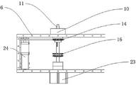
Fig. 1 is a schematic structural view of a rotary leak detection device according to the present invention;
fig. 2 is a top view of a conveyor of a rotary leak detection apparatus of the present invention;
fig. 3 is a schematic structural diagram of a first state of a water tank lifting platform of the rotary leak detection device according to the present invention;
fig. 4 is a structural diagram of a water tank lifting platform of the rotary leak detection device in a second state;
fig. 5 is a schematic structural view of a motor driven sprocket of the rotary leak detection device according to the present invention;
fig. 6 is a schematic structural view of an aluminum sleeve for limiting a rotating shaft of the rotary leak detection device of the present invention.
The reference numerals are explained below:
1. a 180 degree rotary cylinder; 2. rotating the cylinder block; 3. a coupling; 4. a bearing seat; 5. rotating shafts at two ends of the main box body are subjected to leakage detection; 6. detecting a leakage of the main box body; 7. a water tank; 8. a water tank lifting platform; 9. a conveyor; 10. a holder; 11. a rotating shaft; 12. the motor driven chain wheel uses the hollow rotating shaft; 13. the motor driven chain wheel uses the spacing flange of hollow rotating shaft; 14. a motor driven sprocket; 15. the motor driven chain wheel fixes the screw and rotates and drives; 16. a double sprocket; 17. compressing the gasket; 18. an aluminum sleeve for limiting the rotating shaft; 19. a rotating shaft lower flange; 20. fixing screws; 21. the cylinder shaft is connected with an aluminum sleeve; 22. a cylinder shaft; 23. a telescopic cylinder; 24. and clamping the motor.
Detailed Description
In the description of the present invention, it is to be understood that the terms "center", "longitudinal", "lateral", "up", "down", "front", "back", "left", "right", "vertical", "horizontal", "top", "bottom", "inner", "outer", and the like, indicate orientations or positional relationships based on the orientations or positional relationships shown in the drawings, and are used merely for convenience of description and for simplicity of description, and do not indicate or imply that the device or element being referred to must have a particular orientation, be constructed and operated in a particular orientation, and therefore, should not be construed as limiting the present invention. Furthermore, the terms "first", "second", etc. are used for descriptive purposes only and are not to be construed as indicating or implying relative importance or implicitly indicating the number of technical features indicated. Thus, a feature defined as "first," "second," etc. may explicitly or implicitly include one or more of that feature. In the description of the present invention, "a plurality" means two or more unless otherwise specified.
In the description of the present invention, it is to be noted that, unless otherwise explicitly specified or limited, the terms "mounted," "connected," and "connected" are to be construed broadly, and may be, for example, fixedly connected, detachably connected, or integrally connected; can be mechanically or electrically connected; they may be connected directly or indirectly through intervening media, or they may be interconnected between two elements. The specific meaning of the above terms in the present invention can be understood by those of ordinary skill in the art through specific situations.
The present invention will be further explained with reference to the accompanying drawings:
example 1
As shown in fig. 1-6, a rotary leak detection device comprises a leak detection main box body 6, a water tank 7, a transmission machine 9 and a telescopic cylinder 23, wherein the leak detection main box body 6 is arranged on the inner side of the transmission machine 9, the water tank 7 is arranged on the lower side of the leak detection main box body 6, the lower end of the water tank 7 is connected with the transmission machine 9 through a water tank lifting platform 8, the power end of the leak detection main box body 6 is connected with rotating shafts 5 at two ends of the leak detection main box body, the rotating shafts 5 at two ends of the leak detection main box body are connected with the transmission machine 9 through bearing blocks 4, the power ends of the rotating shafts 5 at two ends of the leak detection main box body are connected with a;
a telescopic cylinder 23 is arranged on the outer end surface of the leakage detection main box body 6, an aluminum sleeve 21 for cylinder shaft connection is arranged at the power end of the telescopic cylinder 23 through the outside of a cylinder shaft 22, a rotating shaft 11 is arranged at the upper end of the cylinder shaft 22, a hollow rotating shaft 12 for a motor driven sprocket is arranged at the outer side of the rotating shaft 11, a fixing screw 20 is arranged on the aluminum sleeve 21 for cylinder shaft connection, a rotating shaft lower flange 19 is arranged at the upper side of the aluminum sleeve 21 for cylinder shaft connection, an aluminum sleeve 18 for rotating shaft limiting is arranged at the upper side of the rotating shaft lower flange 19, a pressing gasket 17 is arranged at the upper side of the rotating shaft limiting aluminum sleeve 18, a double sprocket 16 is connected at the outer side of the hollow rotating shaft 12 for the motor driven sprocket, a motor driven sprocket 14 is arranged at the upper side of the double sprocket 16, the motor driven sprocket 14 is connected with the hollow rotating shaft 12 for the motor driven sprocket through a motor driven sprocket fixing screw and rotating transmission 15, and a hollow rotating shaft limiting flange 13 for the motor driven sprocket is arranged at the upper side of the motor driven sprocket 14, the upper end of the rotating shaft 11 is connected with the clamping seat 10, the motor driven chain wheel 14 is connected with the clamping motor 24 through a chain, and the two double chain wheels 16 are connected through the chain.
Preferably: the rotary cylinder seat 2 is connected with the 180-degree rotary cylinder 1 and the transmission machine 9 through bolts, the coupling 3 is connected with the 180-degree rotary cylinder 1 and the rotary shafts 5 at two ends of the leak detection main box body through bolts, the transmission machine 9 plays a supporting role, and the 180-degree rotary cylinder 1 plays a role in rotating the leak detection main box body 6; the water tank lifting platform 8 is connected with the conveyor 9 and the water tank 7 through bolts, and the water tank lifting platform 8 plays a role in providing lifting force for the water tank 7; the clamping motor 24 and the telescopic cylinder 23 are connected with the leak detection main box body 6 through bolts, the clamping motor 24 drives the rotating shaft 11 to rotate, and the telescopic cylinder 23 drives the rotating shaft 11 to stretch; the rotation axis-limiting aluminum sleeve 18 is rotatably connected to the cylinder shaft-connecting aluminum sleeve 21, and the rotation axis-limiting aluminum sleeve 18 is fitted to the cylinder shaft-connecting aluminum sleeve 21 so as to be driven to extend and retract while the rotation axis 11 is rotated.
The working principle is as follows: 9 inboard transmission device of transmitter transports the jar to holder 10 one side, press from both sides tight motor 24 and pass through the chain and drive motor driven sprocket 14 and motor driven sprocket and use hollow rotation axis 12, thereby it is rotatory to drive rotation axis 11 and holder 10, make the jar rotated to on holder 10, then telescopic cylinder 23 starts to drive rotation axis 11 and remove to the inboard, take up the jar on the flange, guarantee the leakproofness, rotatory cylinder frame 2 drives the upset of leak hunting main tank body 6 this moment, holder 10 that has the jar is rotatory to the downside, water tank elevating platform 8 drives the water tank 7 and rises this moment, immerse the jar in the aquatic, detect sealed the jar, detect back water tank 7 descends, rotatory cylinder frame 2 drives the upset of leak hunting main tank body 6 once more, overturn second group jar below, carry out sealed detection once more.
The foregoing illustrates and describes the principles, general features, and advantages of the present invention. It will be understood by those skilled in the art that the present invention is not limited to the above embodiments, and that the foregoing embodiments and descriptions are provided only to illustrate the principles of the present invention without departing from the spirit and scope of the present invention.
Claims (5)
1. A rotation type leak hunting device which characterized in that: the leakage detection device comprises a leakage detection main box body (6), a water tank (7), a conveyor (9) and a telescopic cylinder (23), wherein the leakage detection main box body (6) is arranged on the inner side of the conveyor (9), the water tank (7) is arranged on the lower side of the leakage detection main box body (6), the lower end of the water tank (7) is connected with the conveyor (9) through a water tank lifting platform (8), the power end of the leakage detection main box body (6) is connected with rotating shafts (5) at two ends of the leakage detection main box body, the rotating shafts (5) at two ends of the leakage detection main box body are connected with the conveyor (9) through bearing seats (4), the power ends of the rotating shafts (5) at two ends of the leakage detection main box body are connected with a 180-degree rotating cylinder (1) through a coupler (3), and the outside of the 180-degree rotating cylinder (1) is connected with the conveyor (9) through a rotating cylinder seat (2);
the outer end face of the leakage detection main box body (6) is provided with the telescopic cylinder (23), the power end of the telescopic cylinder (23) is provided with an aluminum sleeve (21) for connecting a cylinder shaft through the outside of a cylinder shaft (22), the upper end of the cylinder shaft (22) is provided with a rotating shaft (11), the outside of the rotating shaft (11) is provided with a hollow rotating shaft (12) for a motor driven sprocket, the aluminum sleeve (21) for connecting the cylinder shaft is provided with a fixing screw (20), the upper side of the aluminum sleeve (21) for connecting the cylinder shaft is provided with a rotating shaft lower flange (19), the upper side of the rotating shaft lower flange (19) is provided with a rotating shaft limiting aluminum sleeve (18), the upper side of the rotating shaft limiting aluminum sleeve (18) is provided with a pressing gasket (17), a double sprocket (16) is connected to the outside of the hollow rotating shaft (12) for the motor driven sprocket, and the upper side of the double sprocket (16) is provided with a motor driven sprocket (14), motor driven sprocket (14) are connected through motor driven sprocket fixed screw and rotatory transmission (15) motor driven sprocket is with hollow rotation axis (12), motor driven sprocket (14) upside is provided with motor driven sprocket with hollow rotation axis spacing flange (13), holder (10) is connected to rotation axis (11) upper end, motor driven sprocket (14) are connected through the chain and are pressed from both sides tight motor (24), two connect through the chain between double sprocket (16).
2. A rotary leak detection apparatus as defined in claim 1, wherein: the rotary cylinder seat (2) is connected with the 180-degree rotary cylinder (1) and the conveyor (9) through bolts, and the coupler (3) is connected with the 180-degree rotary cylinder (1) and rotating shafts (5) at two ends of the leak detection main box body through bolts.
3. A rotary leak detection apparatus as defined in claim 1, wherein: the water tank lifting platform (8) is connected with the conveyor (9) and the water tank (7) through bolts.
4. A rotary leak detection apparatus as defined in claim 1, wherein: the clamping motor (24) and the telescopic cylinder (23) are connected with the leak detection main box body (6) through bolts.
5. A rotary leak detection apparatus as defined in claim 1, wherein: the rotating shaft limiting aluminum sleeve (18) is rotatably connected with the cylinder shaft connecting aluminum sleeve (21).
Priority Applications (1)
| Application Number | Priority Date | Filing Date | Title |
|---|---|---|---|
| CN202022189575.6U CN214121504U (en) | 2020-09-29 | 2020-09-29 | Rotation type leak hunting device |
Applications Claiming Priority (1)
| Application Number | Priority Date | Filing Date | Title |
|---|---|---|---|
| CN202022189575.6U CN214121504U (en) | 2020-09-29 | 2020-09-29 | Rotation type leak hunting device |
Publications (1)
| Publication Number | Publication Date |
|---|---|
| CN214121504U true CN214121504U (en) | 2021-09-03 |
Family
ID=77499046
Family Applications (1)
| Application Number | Title | Priority Date | Filing Date |
|---|---|---|---|
| CN202022189575.6U Active CN214121504U (en) | 2020-09-29 | 2020-09-29 | Rotation type leak hunting device |
Country Status (1)
| Country | Link |
|---|---|
| CN (1) | CN214121504U (en) |
Cited By (1)
| Publication number | Priority date | Publication date | Assignee | Title |
|---|---|---|---|---|
| CN114835073A (en) * | 2022-04-11 | 2022-08-02 | 苏州新实医疗科技有限公司 | Clamping detection device, clamping equipment with same and cover opening and closing device |
-
2020
- 2020-09-29 CN CN202022189575.6U patent/CN214121504U/en active Active
Cited By (2)
| Publication number | Priority date | Publication date | Assignee | Title |
|---|---|---|---|---|
| CN114835073A (en) * | 2022-04-11 | 2022-08-02 | 苏州新实医疗科技有限公司 | Clamping detection device, clamping equipment with same and cover opening and closing device |
| CN114835073B (en) * | 2022-04-11 | 2024-01-12 | 苏州新实医疗科技有限公司 | Clamping detection device and clamping equipment with same and cover opening and closing device |
Similar Documents
| Publication | Publication Date | Title |
|---|---|---|
| CN101616753B (en) | Surface treatment equipment | |
| CN214121504U (en) | Rotation type leak hunting device | |
| CN109029860A (en) | A kind of food pack gas leak detection device | |
| CN208432373U (en) | A kind of food pack gas leak detection device | |
| CN211373976U (en) | Canned product gas tightness check out test set | |
| CN211102557U (en) | Ultra-precise clean bearing press-fitting equipment | |
| CN110759140B (en) | Corrugated paper flattening conveying frame | |
| CN215627645U (en) | Edge sealing device for vacuum glass processing | |
| CN216247008U (en) | Sealing detection device for hydraulic oil cylinder production | |
| CN213141355U (en) | Seafood can seals flowing water apparatus for producing | |
| CN217560882U (en) | Sealing tightness detection device for packaging bag | |
| CN216835900U (en) | A forming device for grinding gasket production | |
| CN214031622U (en) | Full-automatic capping device of water chestnut juice beverage | |
| CN215931210U (en) | Air tightness detection device for new energy battery | |
| CN212285191U (en) | Inner wall cleaning mechanism of pressure vessel jar | |
| CN213505913U (en) | Beverage filling device | |
| CN217819234U (en) | Leak detection tool for pop can cover | |
| CN214422629U (en) | Automatic liquid strain inoculating machine | |
| CN209852945U (en) | Vacuum insulation tank convenient to clean | |
| CN220306304U (en) | Electrolyte infiltration device and battery production line | |
| CN216081928U (en) | Air tightness detection device for sealed cabin for bio-pharmaceuticals | |
| CN215544639U (en) | Forge automatic discharging device | |
| CN215439613U (en) | Differential pressure type beverage filling machine | |
| CN217418662U (en) | A pickling device for vegetables processing | |
| CN217921426U (en) | Anti-freezing solution filling equipment |
Legal Events
| Date | Code | Title | Description |
|---|---|---|---|
| GR01 | Patent grant | ||
| GR01 | Patent grant |