CN214117074U - Rotary eddy current tuned mass damper - Google Patents
Rotary eddy current tuned mass damper Download PDFInfo
- Publication number
- CN214117074U CN214117074U CN202022324774.3U CN202022324774U CN214117074U CN 214117074 U CN214117074 U CN 214117074U CN 202022324774 U CN202022324774 U CN 202022324774U CN 214117074 U CN214117074 U CN 214117074U
- Authority
- CN
- China
- Prior art keywords
- magnetic conduction
- plectane
- eddy current
- ball screw
- plate
- Prior art date
- Legal status (The legal status is an assumption and is not a legal conclusion. Google has not performed a legal analysis and makes no representation as to the accuracy of the status listed.)
- Active
Links
Images


Abstract
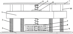
The utility model discloses a harmonious mass damper of rotation type eddy current, including the quality piece, the quality piece links with coil spring, and coil spring links with the lower plate, open the hole in quality piece center, the quality piece center is arranged in to the ball nut, the central trompil of upper and lower magnetic conduction plectane, screw rod pass nut and magnetic conduction plectane, respectively link a antifriction bearing from top to bottom, go up antifriction bearing and upper plate and link, antifriction bearing arranges down magnetic conduction plectane center and lower plate in and links, the conductor plectane links to each other with the screw rod, the permanent magnet links to each other with the magnetic conduction plectane, and upper and lower magnetic conduction plectane is linked by the support, arranges in on the lower plate. The utility model discloses can trun into the damping coefficient of rotation type eddy current damping part to the equivalent axial damping coefficient who amplifies the multiplicities, damping force size can realize adjusting through the interval of adjusting magnetic conduction plectane and conductor plectane simultaneously, helps improving the attenuator overall control effect, guarantees its good damping effect of performance.
Description
Technical Field
The utility model relates to a attenuator especially relates to a harmonious mass damper of rotation type eddy current.
Background
At present, the civil engineering field widely adopts a tuned mass damper to control structural vibration, most energy consumption elements of the tuned mass damper are viscous dampers, and the dampers have the problems of liquid leakage, low durability, difficult later damping parameter adjustment and the like along with the passage of time. And if the energy dissipation element adopts an eddy current damper, the problems can be effectively solved. The eddy current damper utilizes the electromagnetic induction principle, can produce the eddy current in the conductor plate when the conductor plate cuts magnetic line of force, and the eddy current produces the new magnetic field opposite with former magnetic field direction again, produces the lorentz force that hinders the conductor plate motion, and the resistance effect of conductor plate simultaneously converts the kinetic energy that obtains into heat energy through the eddy current and dissipates away. The hydraulic oil cylinder does not depend on mechanical friction energy consumption, does not have working fluid, does not have the problems of liquid leakage and sealing, and has high reliability and good durability.
The structure form of the eddy current tuned mass damper is single, and the eddy current tuned mass damper is mostly in a plate type and relative movement mode. However, in the case of the plate type or the relative movement type, the eddy current damper itself has a relatively low damping coefficient, and it is difficult to satisfy the damping force required for the large civil engineering structure. The energy consumption efficiency of the eddy current tuned mass damper can be obviously improved by adopting the ball screw pair transmission system.
SUMMERY OF THE UTILITY MODEL
The utility model aims at providing a harmonious quality attenuator of rotation type eddy current turns into the damping coefficient that enlarges many times through adopting ball screw rotational system with the damping coefficient of rotation type eddy current damping part, and the damping force size can be realized adjusting through the interval of adjusting magnetic conduction plectane and conductor plectane simultaneously, helps improving the attenuator overall control effect, guarantees that its performance is good shock attenuation effect.
To the problem existing in the prior art, the technical scheme of the utility model as follows:
a rotary eddy current tuned mass damper comprises a mass block, a spiral steel spring, a bottom plate, a ball screw rod, a ball screw nut, a rolling bearing, a magnetic conduction circular plate, a conductor circular plate, a permanent magnet and an outer support; the mass block is rectangular, the number of the outer supports is four, the top ends of the four outer supports are connected with the upper top plate after penetrating through four corners of the mass block, the bottom ends of the four outer supports are connected with the lower bottom plate, a spiral steel spring is sleeved on the outer support between the mass block and the lower bottom plate, a hole is formed in the center of the mass block, the lower part of a ball screw nut is inserted into the hole of the mass block, the number of the magnetic conduction circular plates is two, the two magnetic conduction circular plates are arranged up and down and are arranged at the center of the lower bottom plate after being connected together through the four supporting columns, and the four supporting columns are arranged at equal intervals along the circumferential direction of the magnetic conduction circular plates; a conductor circular plate and a plurality of permanent magnets are arranged in a space formed by the two magnetic conduction circular plates and the four support columns; conductor plectane and two magnetic conduction plectanes parallel arrangement to be located the central line department of two upper and lower magnetic conduction plectanes, conductor plectane and two upper and lower magnetic conduction plectanes all open a hole in the center, pass through antifriction bearing and be connected with last roof behind the ball screw nut is passed on ball screw's top, pass through antifriction bearing and be connected with the lower plate behind the centre bore of first magnetic conduction plectane, conductor plectane and second magnetic conduction plectane is passed to ball screw's bottom, ball screw links together with the conductor plectane.
Further, the mass block is formed by welding steel plates.
Furthermore, the ball screw nut is arranged in the center of the mass block and is welded or connected with the mass block through a bolt.
Furthermore, the top end of the spiral steel spring is welded with the mass block, and the bottom end of the spiral steel spring is welded with the lower bottom plate.
Further, both ends of the ball screw rod are welded with the rolling bearings.
Further, the upper top plate and the lower bottom plate are respectively connected with the rolling bearings on the corresponding sides in a welding mode.
Further, the permanent magnet is welded or bolted with the magnetic conduction circular plate.
Furthermore, the magnetic conduction round plate positioned at the lower part is welded or connected on the lower bottom plate through bolts.
The utility model has the advantages and beneficial effects that:
the utility model relates to a harmonious mass damper of rotation type eddy current, because the quality piece is connected with the coil spring, the coil spring is connected with the lower plate, and the quality piece center is arranged in to the ball nut, and the ball screw rod passes ball nut and magnetic conduction plectane, respectively connects a antifriction bearing from top to bottom, goes up antifriction bearing and last roof and joins, and lower antifriction bearing arranges magnetic conduction plectane center down in and joins with the lower plate, the conductor plectane links to each other with the ball screw rod, the permanent magnet links to each other with the magnetic conduction plectane, and upper and lower magnetic conduction plectane is linked by the support column, arranges in on the lower plate. Through adopting above-mentioned structure, when vertical vibration action was used, the quality piece produced vertical vibration along outer supporting with the help of the ball nut that the spiral steel spring drove in the quality piece together, and the vertical vibration of nut drove the lead screw and takes place to rotate, drives the conductor plectane simultaneously and takes place to rotate, and the magnetic field production damping force between the cutting permanent magnet consumes energy. The damping coefficient of the rotary eddy current damping part is converted into an equivalent damping coefficient which is amplified by multiple times by adopting a ball screw rotating system. Meanwhile, the damping force can be adjusted by adjusting the distance between the magnetic conduction circular plate and the conductor circular plate, so that the overall control effect of the damper is improved, and the damper is ensured to exert a good vibration reduction effect.
Drawings
Fig. 1 is a three-dimensional schematic view of a rotary eddy current tuned mass damper according to the present invention;
fig. 2 is a schematic front view of a rotary eddy current tuned mass damper according to the present invention;
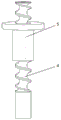
fig. 3 is a three-dimensional schematic view of a ball screw system according to the present invention;
fig. 4 is a three-dimensional schematic view of the magnetic conduction circular plate and the permanent magnet of the present invention;
fig. 5 is a three-dimensional schematic view of the middle rolling bearing of the present invention.
In the figure: 1 is a mass block, 2 is a spiral steel spring, 3 is a bottom plate, 4 is a ball screw rod, 5 is a ball screw nut, 6 is a rolling bearing, 7 is a magnetic conduction circular plate, 8 is a conductor circular plate, 9 is a permanent magnet, 10 is an outer support, 11 is an upper top plate, and 12 is a support column.
Detailed Description
The present invention will be described in further detail with reference to the following drawings and specific embodiments.
As shown in fig. 1 and 2, the utility model relates to a harmonious mass damper of rotation type eddy current, including quality piece 1, coil spring 2, bottom plate 3, ball screw 4, ball nut 5, antifriction bearing 6, magnetic conduction plectane 7, conductor plectane 8, permanent magnet 9, outer support 10. As shown in fig. 3, the ball screw 4, the ball screw nut 5, and the steel balls constitute a ball screw rotation system. The mass block is rectangular and is formed by welding steel plates. The four outer supports penetrate through four corners of the mass block, the top ends of the four outer supports are connected with the upper top plate 11, the bottom ends of the four outer supports are connected with the lower bottom plate 3, the top ends and the bottom ends of the spiral steel springs, 2, sleeved on the outer supports between the mass block and the lower bottom plate are connected to the mass block 1 and the lower bottom plate respectively, a hole is formed in the center of the mass block 1, and the lower portion of the ball screw nut 5 is inserted into the hole of the mass block and is welded or connected with the mass block 1 through bolts. As shown in fig. 4 and 5, the number of the magnetic conduction circular plates 7 is two, the two magnetic conduction circular plates 7 are arranged up and down and connected together through four support columns and then arranged at the center of the lower bottom plate, and the magnetic conduction circular plate 7 positioned below is welded or bolted on the lower bottom plate. The four support columns are arranged at equal intervals along the circumferential direction of the magnetic conduction circular plate; a conductor circular plate 8 and a plurality of permanent magnets 9 are arranged in a space formed by the two magnetic conduction circular plates and the four supporting columns 12. The permanent magnet 9 is welded or bolted with the magnetic conduction circular plate 7. Conductor plectane 8 and two magnetic conduction plectanes 7 parallel arrangement, and be located the central line department of two upper and lower magnetic conduction plectanes 7, conductor plectane and two upper and lower magnetic conduction plectanes all open a hole in the center, pass through antifriction bearing 6 and be connected with last roof behind the ball nut is passed on the top of ball screw rod 4, pass through first magnetic conduction plectane in the bottom of ball screw rod 4, pass through antifriction bearing and be connected with the lower plate behind the centre bore of conductor plectane and second magnetic conduction plectane, ball screw rod and conductor plectane link together, there is not relative motion between the two. The rolling bearing 6 positioned at the lower part is arranged below the center of the hole of the lower magnetic conduction circular plate 8.
The top end of the spiral steel spring 2 is welded with the mass block 1, and the bottom end of the spiral steel spring is welded with the lower bottom plate 3. And two ends of the ball screw rod 4 are welded with the rolling bearings 6. The upper top plate 3 and the lower bottom plate 3 are respectively connected with the rolling bearings on the corresponding sides in a welding mode.
The working principle of the utility model is as follows:
when vertical vibration acts, the mass block 1 drives the ball screw nut 5 in the mass block 1 to generate vertical vibration along the outer support 10 by means of the spiral steel spring 2, the vertical vibration of the nut 5 drives the screw rod 4 to rotate, meanwhile, the conductor circular plate 8 is driven to rotate, and the magnetic field between the cutting permanent magnets 9 generates damping force to dissipate energy. The damping coefficient of the rotary eddy current damping part is converted into an equivalent damping coefficient which is amplified by multiple times by adopting a ball screw rotating system. Meanwhile, the damping force can be adjusted by adjusting the distance between the magnetic conduction circular plate 7 and the conductor circular plate 8, so that the overall control effect of the damper is improved, and the damper is ensured to exert a good damping effect.
The above embodiments are merely preferred embodiments of the present invention, and should not be considered as limiting the present invention, and the features in the embodiments and the embodiments in the present application may be arbitrarily combined with each other without conflict. The protection scope of the present invention should be defined by the claims. Equivalents including technical features described in the claims are intended to be included within the scope of protection. And equivalent replacement modifications within the scope are also within the protection scope of the present invention.
Claims (8)
1. A rotary eddy current tuned mass damper is characterized in that: the device comprises a mass block (1), a spiral steel spring (2), a bottom plate (3), a ball screw rod (4), a ball screw nut (5), a rolling bearing (6), a magnetic conduction circular plate (7), a conductor circular plate (8), a permanent magnet (9) and an outer support (10); the mass block is rectangular, the number of the outer supports is four, the top ends of the four outer supports penetrate through four corners of the mass block and are connected with an upper top plate (11), the bottom ends of the four outer supports are connected with a lower bottom plate (3), a spiral steel spring (2) is sleeved on the outer support between the mass block and the lower bottom plate, a hole is formed in the center of the mass block (1), the lower portion of a ball screw nut (5) is inserted into the hole of the mass block, the number of the magnetic conduction circular plates (7) is two, the two magnetic conduction circular plates (7) are arranged up and down and are connected together through four support columns (12) and then are arranged at the center of the lower bottom plate, and the four support columns are arranged at equal intervals along the circumferential direction of the magnetic conduction circular plates; a conductor circular plate (8) and a plurality of permanent magnets (9) are arranged in a space formed by the two magnetic conduction circular plates and the four support columns; conductor plectane (8) and two magnetic conduction plectanes (7) parallel arrangement, and be located the central line department of two upper and lower magnetic conduction plectanes (7), conductor plectane and two upper and lower magnetic conduction plectanes all are at the central trompil, pass through antifriction bearing (6) and be connected with last roof behind the ball screw nut on the top of ball screw (4), pass first magnetic conduction plectane in the bottom of ball screw (4), pass through antifriction bearing and be connected with the lower plate behind the centre bore of conductor plectane and second magnetic conduction plectane, the ball screw is in the same place with the conductor plectane links together.
2. A rotary eddy current tuned mass damper according to claim 1, wherein: the mass block (1) is formed by welding steel plates.
3. A rotary eddy current tuned mass damper according to claim 2, wherein: the ball screw nut (5) is arranged in the center of the mass block (1) and is welded with the mass block (1) or is connected with the mass block through a bolt.
4. A rotary eddy current tuned mass damper according to claim 1, wherein: the top end of the spiral steel spring (2) is welded with the mass block (1), and the bottom end of the spiral steel spring is welded with the lower bottom plate (3).
5. A rotary eddy current tuned mass damper according to claim 1, wherein: and two ends of the ball screw rod (4) are welded with the rolling bearing (6).
6. A rotary eddy current tuned mass damper according to claim 1, wherein: the upper top plate (11) and the lower bottom plate (3) are respectively connected with the rolling bearings on the corresponding sides in a welding mode.
7. A rotary eddy current tuned mass damper according to claim 1, wherein: the permanent magnet (9) is welded or connected with the magnetic conduction circular plate (7) through bolts.
8. A rotary eddy current tuned mass damper according to claim 1, wherein: the magnetic conduction round plate (7) positioned at the lower part is welded or bolted on the lower bottom plate.
Priority Applications (1)
| Application Number | Priority Date | Filing Date | Title |
|---|---|---|---|
| CN202022324774.3U CN214117074U (en) | 2020-10-19 | 2020-10-19 | Rotary eddy current tuned mass damper |
Applications Claiming Priority (1)
| Application Number | Priority Date | Filing Date | Title |
|---|---|---|---|
| CN202022324774.3U CN214117074U (en) | 2020-10-19 | 2020-10-19 | Rotary eddy current tuned mass damper |
Publications (1)
| Publication Number | Publication Date |
|---|---|
| CN214117074U true CN214117074U (en) | 2021-09-03 |
Family
ID=77499972
Family Applications (1)
| Application Number | Title | Priority Date | Filing Date |
|---|---|---|---|
| CN202022324774.3U Active CN214117074U (en) | 2020-10-19 | 2020-10-19 | Rotary eddy current tuned mass damper |
Country Status (1)
| Country | Link |
|---|---|
| CN (1) | CN214117074U (en) |
Cited By (1)
| Publication number | Priority date | Publication date | Assignee | Title |
|---|---|---|---|---|
| CN114704586A (en) * | 2022-03-18 | 2022-07-05 | 徐州徐工基础工程机械有限公司 | Universal coordinated mass damper |
-
2020
- 2020-10-19 CN CN202022324774.3U patent/CN214117074U/en active Active
Cited By (2)
| Publication number | Priority date | Publication date | Assignee | Title |
|---|---|---|---|---|
| CN114704586A (en) * | 2022-03-18 | 2022-07-05 | 徐州徐工基础工程机械有限公司 | Universal coordinated mass damper |
| CN114704586B (en) * | 2022-03-18 | 2023-09-15 | 徐州徐工基础工程机械有限公司 | Universal coordination mass damper |
Similar Documents
| Publication | Publication Date | Title |
|---|---|---|
| CN214329378U (en) | Rotary eddy current tuned inerter damper | |
| US10451142B2 (en) | Outer cup rotary axial eddy current damper | |
| CN103821861B (en) | Axial eddy current damper based on spiral transmission method | |
| CN109184018B (en) | Multi-dimensional eddy current tuning mass damper | |
| CN104265818B (en) | Outer cup rotary axial eddy current damper | |
| CN112127498A (en) | Rotary eddy current tuned mass damper | |
| CN103775549B (en) | Eccentric eddy current tuned mass damping device | |
| CN108730410B (en) | Adjustable inertial mass damper | |
| KR102339773B1 (en) | Eddy Current Damper | |
| CN109751352B (en) | Axial displacement amplification type eddy current damper | |
| CN214117074U (en) | Rotary eddy current tuned mass damper | |
| CN110805651B (en) | Self-adaptive adjusting eddy current damper | |
| CN113202202A (en) | Novel tuned inertial mass rotary damper | |
| CN111219437B (en) | Magnetorheological particle damper capable of recycling energy | |
| CN106855092B (en) | A kind of dynamic vibration absorber and its dynamic absorber method with movement conversion mechanism | |
| CN210947235U (en) | Connecting beam shearing displacement amplification type eddy current damper | |
| CN203594127U (en) | Rotary shearing plate damper with power outlet base | |
| CN107620396A (en) | A kind of half active current vortex laminated rubber bases system | |
| CN109577725B (en) | Nonlinear combined damper | |
| CN212376380U (en) | Damping-adjustable energy trap device of magnetorheological damper | |
| CN204781414U (en) | Harmonious viscid mass damper | |
| CN114645580B (en) | Self-resetting rigidity-changing friction damping device based on permanent magnet repulsive force | |
| CN110578297A (en) | eddy current damper suitable for any vibration direction of inhaul cable | |
| CN103469924A (en) | Electromagnetic energy consumption damper | |
| CN112081260A (en) | Novel steel bar rotary friction damper |
Legal Events
| Date | Code | Title | Description |
|---|---|---|---|
| GR01 | Patent grant | ||
| GR01 | Patent grant |