CN214116152U - Assembled ditch body and combination side ditch - Google Patents
Assembled ditch body and combination side ditch Download PDFInfo
- Publication number
- CN214116152U CN214116152U CN202022954036.7U CN202022954036U CN214116152U CN 214116152 U CN214116152 U CN 214116152U CN 202022954036 U CN202022954036 U CN 202022954036U CN 214116152 U CN214116152 U CN 214116152U
- Authority
- CN
- China
- Prior art keywords
- curb plate
- base
- plate
- shaped member
- ditch
- Prior art date
- Legal status (The legal status is an assumption and is not a legal conclusion. Google has not performed a legal analysis and makes no representation as to the accuracy of the status listed.)
- Active
Links
- 239000000853 adhesive Substances 0.000 claims description 10
- 230000001070 adhesive effect Effects 0.000 claims description 10
- 239000002131 composite material Substances 0.000 claims 2
- 239000011230 binding agent Substances 0.000 abstract 2
- XLYOFNOQVPJJNP-UHFFFAOYSA-N water Substances O XLYOFNOQVPJJNP-UHFFFAOYSA-N 0.000 description 5
- 238000009412 basement excavation Methods 0.000 description 4
- 238000009825 accumulation Methods 0.000 description 2
- 230000002411 adverse Effects 0.000 description 2
- 230000000694 effects Effects 0.000 description 2
- 230000009286 beneficial effect Effects 0.000 description 1
- 238000010586 diagram Methods 0.000 description 1
- 238000000034 method Methods 0.000 description 1
Images


Classifications
-
- Y—GENERAL TAGGING OF NEW TECHNOLOGICAL DEVELOPMENTS; GENERAL TAGGING OF CROSS-SECTIONAL TECHNOLOGIES SPANNING OVER SEVERAL SECTIONS OF THE IPC; TECHNICAL SUBJECTS COVERED BY FORMER USPC CROSS-REFERENCE ART COLLECTIONS [XRACs] AND DIGESTS
- Y02—TECHNOLOGIES OR APPLICATIONS FOR MITIGATION OR ADAPTATION AGAINST CLIMATE CHANGE
- Y02A—TECHNOLOGIES FOR ADAPTATION TO CLIMATE CHANGE
- Y02A30/00—Adapting or protecting infrastructure or their operation
- Y02A30/60—Planning or developing urban green infrastructure
Landscapes
- Road Paving Structures (AREA)
Abstract
Assembled ditch body and combination side ditch, relate to road engineering technical field, the aforesaid partly assembled ditch body, including a plurality of bases of splicing along the channel extending direction, first curb plate and second curb plate, be equipped with logical groove or the mortise that is used for the first curb plate of cartridge on the base, first curb plate cartridge is connected in leading to groove or mortise and is fixed through the binder, the slope of mountain face that the second curb plate hugs closely to be located the base outside sets up, insert in the space between base and the slope of mountain face in the bottom of second curb plate, the second curb plate supports to lean on and live the base and through binder and base fixed connection becomes integrative, second curb plate and first curb plate interval distance, thereby form drainage channel between the two. The utility model discloses an overall structure is very simple, compact to individual part can unpack apart and transport, assembles it during site operation again, can set up everywhere domatic according to the height and the ponding volume of the slope body, not limit to position and quantity.
Description
Technical Field
The utility model relates to a road engineering technical field, in particular to assembled ditch body and combination side ditch.
Background
The mountain-side highway mainly depends on the ditch body to drain away the road surface and mountain body flowing water near one side of the mountain body, when the rainfall is larger, because the mountain body catchment area is larger, the ditch body which only depends on the traditional structure on one side of the mountain body near the mountain body is often difficult to meet the drainage requirement, the condition that the water is too much to cross the road surface is easy to appear, and in order to solve the problem, people set up the combined ditch body with the high-level ditch body and the low-level ditch body overlapped on one side of the mountain body with the larger water accumulation area.
Chinese patent document CN108999057A discloses a stacked ditch structure, in which a high-level ditch body is stacked on a low-level ditch body, rainwater on the road surface is drained away through the low-level ditch body, mountain flowing water is drained away through the high-level ditch body, and two drainage paths are isolated from each other and do not interfere with each other, so as to ensure that rainwater can be drained away in time and avoid the condition of water accumulation on the road surface. The problems brought by adopting the method are as follows: all components can only be separately placed one by one, and cannot be stacked in a telescopic way, so that the transportation volume is large, and the logistics cost is high.
SUMMERY OF THE UTILITY MODEL
One of the problems to be solved in the utility model is to provide an assembled ditch body convenient for transportation and assembly.
In order to solve the above problem, the utility model adopts the following technical scheme: the utility model provides an assembled ditch body, including a plurality of bases of splicing along the channel extending direction, first curb plate and second curb plate, be equipped with logical groove or the mortise that is used for the first curb plate of cartridge on the base, first curb plate cartridge is connected in leading to groove or mortise and is fixed through the adhesive, the slope surface setting of mountain that the second curb plate hugs closely and is located the base outside, insert in the space between base and the slope surface of mountain in the bottom of second curb plate, the second curb plate supports to lean on and holds the base and become integrative through adhesive and base fixed connection, a section distance in second curb plate and first curb plate interval, thereby form drainage channel between the two.
Furthermore, one side of the first side plate, which faces away from the second side plate, is provided with a supporting lug, one side of the second side plate, which faces the first side plate, is also provided with a supporting lug, and after the first side plate and the second side plate are connected with the base in an inserting manner, all the supporting lugs are located above the base and abut against the base.
Furthermore, the cross section of the base is in a trapezoid shape with the bottom wider than the top, and the through groove or the mortise is arranged at the top of the base; the second side plate is divided into an upper half section and a lower half section by taking the supporting lug as a boundary, and an included angle between the inner side surface of the upper half section and the inner side surface of the lower half section is larger than 90 degrees.
The utility model discloses another problem that solves provides a combination side ditch.
In order to solve the above problem, the utility model adopts the following technical scheme: combination side ditch, assembled ditch body in the above-mentioned, assembled ditch body sets up in the one side of leaning on the massif, still including setting up the L type component that just follows the concatenation of channel extending direction by leaning on body one side, L type component includes the bottom plate that the level set up and vertical setting and the riser that links into an integrated entity with the bottom plate, the bottom plate of L type component passes through the adhesive and fixes, the riser of L type component is close to the body setting of the way and with a curb plate interval one section distance, the top of riser is less than the road surface.
Furthermore, a concrete cushion layer is arranged below the L-shaped component, the L-shaped component is vertically placed on the concrete cushion layer, concrete is poured on the concrete cushion layer, and a bottom plate of the L-shaped component is buried in the concrete.
Further, the top ends of the first side plate and the second side plate are higher than the road surface.
The utility model discloses the beneficial effect who gains lies in: first curb plate and the integrated assembly of second curb plate are on the base, and first curb plate and second curb plate form drainage channel, and the top of first curb plate is higher, has increased the degree of depth of channel in other words, consequently can design more narrowly at the total width of hillside excavation, reduces area, and the degree of depth of digging under for the massif also can design more shallowly simultaneously, can reduce the adverse effect that the excavation channel brought for the domatic stability of massif to a certain extent. The utility model discloses an overall structure is very simple, compact to individual part can unpack apart and transport, assembles it during site operation again, can set up everywhere domatic according to the height and the ponding volume of the slope body, not limit to position and quantity.
Drawings
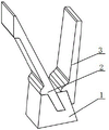
FIG. 1 is an assembly view of an assembled trench body according to an embodiment of the present invention;
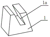
fig. 2 is a schematic view of a base structure with a through groove in embodiment 1 of the present invention;
fig. 3 is a schematic view of a base structure with a mortise in embodiment 2 of the present invention;
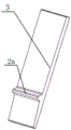
fig. 4 is a schematic structural view of a first side plate in an embodiment of the present invention;
fig. 5 is a schematic diagram of a second side plate structure in the embodiment of the present invention;
fig. 6 is a schematic structural view of a side plate in embodiment 3 of the present invention;
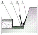
fig. 7 is a sectional view of a combination gutter including the assembled gutter body shown in fig. 1 according to embodiment 3 of the present invention;
in the figure:
1-base 2-first side plate 3-second side plate
4-side plate 1 a-through groove 1 b-mortise
2 a-supporting convex block 4 a-vertical plate 4 b-bottom plate.
Detailed Description
In the present invention, unless otherwise expressly specified or limited, the terms "mounted," "connected," and "fixed" are to be construed broadly and may, for example, be fixedly connected, detachably connected, or integrally connected; they may be directly connected or indirectly connected through an intermediate, and those skilled in the art can understand the specific meaning of the above terms in the present invention according to the specific situation.
Furthermore, in the present invention, the terms "upper", "lower", "front", "rear", "left", "right", "top", "bottom", "inner", "outer", and the like indicate orientations or positional relationships based on the orientations or positional relationships shown in the drawings, and are only for convenience of description and simplification of description, but do not indicate or imply that the device or element referred to must have a specific orientation, be constructed and operated in a specific orientation, and thus, should not be construed as limiting the present invention.
In order to make the improvement of the present invention over the prior art more clearly understood by those skilled in the art, the present invention is further described below with reference to the accompanying drawings.
Example 1
The utility model provides an assembled ditch body, as shown in fig. 1, including a plurality of bases 1 along the concatenation of channel extending direction, first curb plate 2 and second curb plate 3, be equipped with logical groove 1a that is used for cartridge first curb plate 2 on the base 1, as shown in fig. 2, 2 cartridge of first curb plate are connected in logical groove 1a and are fixed through the adhesive, the slope setting of mountain body that is located the base 1 outside is hugged closely to second curb plate 3, insert in the space between base 1 and the slope of mountain body in the bottom of second curb plate 3, second curb plate 3 supports to lean on and holds base 1 and pass through adhesive and base 1 fixed connection becomes integrative, second curb plate 3 and 2a section distances of interval of first curb plate, thereby form drainage channel between the two.
Example 2
This example differs from example 1 in that: the base 1 has a different structure for inserting the first side plate 2, and specifically, as shown in fig. 3, the base 1 is provided with a mortise 1b for inserting the first side plate 2, and the first side plate 2 is inserted and connected in the mortise 1b and fixed by an adhesive.
Specifically, as shown in fig. 3 and 4, the first side plate 2 is provided with a supporting protrusion 2a on a side facing away from the second side plate 3, the second side plate 3 is also provided with a supporting protrusion 2a on a side facing the first side plate 2, and after the first side plate 2 and the second side plate 3 are inserted into the base 1, all the supporting protrusions 2a are located above the base 1 and abut against the base 1.
Specifically, the cross section of the base 1 is in a trapezoid shape with the bottom wider than the top, and the through groove 1a or the mortise 1b is arranged at the top of the base 1; the second side plate 2 is divided into an upper half section and a lower half section by taking the supporting convex block 2a as a boundary, and an included angle between the inner side surface of the upper half section and the inner side surface of the lower half section is larger than 90 degrees.
Example 3
Combination side ditch, assembled ditch body among the above-mentioned, assembled ditch body sets up in the one side that leans on the massif, still including setting up by way body one side and along the L type component 4 of channel extending direction concatenation, L type component 4 includes the bottom plate 4b of level setting and vertical setting and the riser 4a that links into an integrated entity with bottom plate 4b, bottom plate 4b of L type component 4 passes through the adhesive and fixes, L type component 4's riser 4a sets up and a certain distance with first curb plate 2 interval next to the way body, the top of riser 4a is less than the road surface.
Specifically, a concrete cushion is arranged below the L-shaped member 4, the L-shaped member 4 is vertically placed on the concrete cushion, concrete is further poured on the concrete cushion, and the bottom plate 4b of the L-shaped member 4 is buried in the concrete.
Specifically, the top ends of the first side plate 2 and the second side plate 3 are higher than the road surface.
First curb plate and the integrated assembly of second curb plate are on the base, and first curb plate and second curb plate form drainage channel, and the top of first curb plate is higher, has increased the degree of depth of channel in other words, and consequently the total width of excavation can design more narrowly on the hillside, reduces area, and the degree of depth of digging under for the massif also can design more shallowly simultaneously, can reduce the adverse effect that the excavation channel brought for the domatic stability of massif to a certain extent. The utility model discloses an overall structure is very simple, compact to individual part can unpack apart and transport, assembles it during site operation again, can set up everywhere domatic with the ponding according to the height of massif, not limit to position and quantity.
The above-mentioned embodiment is the utility model discloses the implementation scheme of preferred, in addition, the utility model discloses can also realize by other modes, any obvious replacement is all within the protection scope of the utility model under the prerequisite that does not deviate from this technical scheme design.
In order to make it easier for those skilled in the art to understand the improvement of the present invention over the prior art, some drawings and descriptions of the present invention have been simplified, and in order to clarify, some other elements have been omitted from this document, those skilled in the art should recognize that these omitted elements may also constitute the content of the present invention.
Claims (6)
1. Assembled ditch body, its characterized in that: including a plurality of bases (1), first curb plate (2) and second curb plate (3) of splicing along the channel extending direction, be equipped with logical groove (1 a) or mortise (1 b) that are used for cartridge first curb plate (2) on base (1), first curb plate (2) cartridge is connected in logical groove (1 a) or mortise (1 b) and is fixed through the adhesive, the domatic setting of mountain body that is located base (1) outside is hugged closely in second curb plate (3), insert in the space between base (1) and the domatic of mountain body in the bottom of second curb plate (3), second curb plate (3) are supported and are leaned on base (1) and become an organic whole through adhesive and base (1) fixed connection, a section distance in second curb plate (3) and first curb plate (2) interval to form drainage channel between the two.
2. The fabricated trench body of claim 1, wherein: first curb plate (2) are equipped with support lug (2 a) in one side of second curb plate (3) dorsad, second curb plate (3) also are equipped with support lug (2 a) towards one side of first curb plate (2), after base (1) is connected in first curb plate (2) and second curb plate (3) cartridge, all support lug (2 a) all are located base (1) top and support and lean on base (1).
3. The fabricated trench body of claim 1, wherein: the cross section of the base (1) is in a trapezoid shape, the bottom of the cross section of the base is wider than the top of the base, and the through groove (1 a) or the mortise (1 b) is formed in the top of the base (1); the second side plate (3) is divided into an upper half section and a lower half section by taking the supporting convex block (2 a) as a boundary, and an included angle between the inner side surface of the upper half section and the inner side surface of the lower half section is larger than 90 degrees.
4. The combination side ditch, its characterized in that: the assembled ditch comprises an assembled ditch body as claimed in any one of claims 1 to 3, and further comprises an L-shaped member (4) which is arranged on the side close to the mountain and spliced along the extending direction of the channel, wherein the L-shaped member (4) comprises a horizontally arranged bottom plate (4 b) and a vertically arranged vertical plate (4a) which is connected with the bottom plate (4 b) into a whole, the bottom plate (4 b) of the L-shaped member (4) is fixed by an adhesive, the vertical plate (4a) of the L-shaped member (4) is arranged close to the mountain and is spaced from the first side plate (2), and the top end of the vertical plate (4a) is lower than the road surface.
5. The composite gutter as claimed in claim 4, wherein: the L-shaped member (4) is characterized in that a concrete cushion is arranged below the L-shaped member (4), the L-shaped member (4) is vertically placed on the concrete cushion, concrete is poured on the concrete cushion, and a bottom plate (4 b) of the L-shaped member (4) is buried in the concrete.
6. The composite gutter as claimed in claim 4, wherein: the top ends of the first side plate (2) and the second side plate (3) are higher than the road surface.
Priority Applications (1)
| Application Number | Priority Date | Filing Date | Title |
|---|---|---|---|
| CN202022954036.7U CN214116152U (en) | 2020-12-11 | 2020-12-11 | Assembled ditch body and combination side ditch |
Applications Claiming Priority (1)
| Application Number | Priority Date | Filing Date | Title |
|---|---|---|---|
| CN202022954036.7U CN214116152U (en) | 2020-12-11 | 2020-12-11 | Assembled ditch body and combination side ditch |
Publications (1)
| Publication Number | Publication Date |
|---|---|
| CN214116152U true CN214116152U (en) | 2021-09-03 |
Family
ID=77509980
Family Applications (1)
| Application Number | Title | Priority Date | Filing Date |
|---|---|---|---|
| CN202022954036.7U Active CN214116152U (en) | 2020-12-11 | 2020-12-11 | Assembled ditch body and combination side ditch |
Country Status (1)
| Country | Link |
|---|---|
| CN (1) | CN214116152U (en) |
-
2020
- 2020-12-11 CN CN202022954036.7U patent/CN214116152U/en active Active
Similar Documents
| Publication | Publication Date | Title |
|---|---|---|
| CN106836957B (en) | A kind of urban viaduct construction guard fender structure and its installation method | |
| CN214116152U (en) | Assembled ditch body and combination side ditch | |
| CN211621050U (en) | Road pervious concrete pavement water collecting structure | |
| CN209923938U (en) | Assembled supporting construction of small-size rectangle foundation ditch | |
| CN112112242A (en) | Roadbed structure based on rainwater storage and regulation system and construction method thereof | |
| CN114150628B (en) | Rock-fill dam top spillway chute and construction method thereof | |
| CN209907134U (en) | Roadbed widening structure | |
| CN216378979U (en) | Firm type town road structure of mating formation that permeates water | |
| CN214573069U (en) | Integrated combined side ditch and mountain-side highway comprising same | |
| KR101220529B1 (en) | Water resistance construction of softground | |
| CN211498867U (en) | A envelope for underground works excavation foundation ditch engineering on a large scale | |
| CN209338935U (en) | A kind of road structure | |
| CN211947771U (en) | Combined side ditch structure and highway comprising same | |
| CN217517641U (en) | Abrupt slope road retaining wall structure | |
| CN212742832U (en) | Ditch cover plate mounting structure | |
| CN213114171U (en) | Combined side ditch structure and mountain-side highway comprising same | |
| CN214402072U (en) | Drainage ditch for sponge city | |
| KR100716504B1 (en) | Breast Wall having Bent Plate | |
| CN215053213U (en) | Prefabricated assembled supporting construction | |
| JP2016216915A (en) | Connection structure of draining block | |
| CN214459332U (en) | Municipal administration is with preventing ponding type road | |
| CN213596720U (en) | Highway subgrade settlement-preventing device | |
| CN212742063U (en) | Superposed combined side ditch and highway comprising same | |
| CN209779690U (en) | Pin-connected panel city underground comprehensive gallery pipe | |
| CN210066811U (en) | Municipal administration retaining wall structure |
Legal Events
| Date | Code | Title | Description |
|---|---|---|---|
| GR01 | Patent grant | ||
| GR01 | Patent grant | ||
| EE01 | Entry into force of recordation of patent licensing contract |
Assignee: Hunan Yijiu Construction Co.,Ltd. Assignor: HENGYANG JINMING ENVIRONMENTAL TECHNOLOGY Co.,Ltd. Contract record no.: X2023980054388 Denomination of utility model: Prefabricated ditch body and combined side ditch Granted publication date: 20210903 License type: Common License Record date: 20231229 |
|
| EE01 | Entry into force of recordation of patent licensing contract |