CN214059832U - Upper cover groove guiding device - Google Patents
Upper cover groove guiding device Download PDFInfo
- Publication number
- CN214059832U CN214059832U CN202023184649.3U CN202023184649U CN214059832U CN 214059832 U CN214059832 U CN 214059832U CN 202023184649 U CN202023184649 U CN 202023184649U CN 214059832 U CN214059832 U CN 214059832U
- Authority
- CN
- China
- Prior art keywords
- upper cover
- cover
- plate
- bucket
- shifting
- Prior art date
- Legal status (The legal status is an assumption and is not a legal conclusion. Google has not performed a legal analysis and makes no representation as to the accuracy of the status listed.)
- Active
Links
Images
Landscapes
- Closures For Containers (AREA)
Abstract
The utility model discloses an upper cover groove guide device, fight including the upper cover, the fixed intercommunication in bottom that the upper cover was fought has the lid of dialling of fighting the looks adaptation with the upper cover to fight and fights, dials one side that the lid was fought and has seted up the discharge gate, dials and is equipped with guide mechanism in the lid is fought, guide mechanism include with dial the board of dialling of lid fill looks adaptation, dial the opposite side that the lid was fought and be provided with the thrust equipment that promotes and dial board pivoted. The utility model has the advantages that: through setting up the group board, under the effect of thrust equipment, can promote to dial the board rotation to can make and be located group lid fill and the inside bottle lid of upper cover fill can derive along dialling board and discharge gate, reach the purpose of automatic guide, reduce the amount of labour of manpower.
Description
Technical Field
The utility model relates to a top cover machine field, especially a top cover groove stock guide.
Background
The general flow of the existing bottled filling line is from the integration of bottle feeding, filling, lower cover, sealing, labeling and packaging, and in the aspect of the upper cover flow, the upper cover machine needs to replace different bottle caps when producing different products, so that the left unused covers in the material groove of the upper cover machine need to be manually picked up, and the labor is wasted.
SUMMERY OF THE UTILITY MODEL
An object of the utility model is to overcome prior art's shortcoming, provide a upper cover groove stock guide device.
The purpose of the utility model is realized through the following technical scheme:
the utility model provides an upper cover groove guide device, includes the upper cover fill, the fixed intercommunication in bottom of upper cover fill have with the upper cover fill the adaptation dial cover fill, dial one side of cover fill and seted up the discharge gate, dial and be equipped with guide mechanism in the cover fill, guide mechanism includes and dials the board of dialling of cover fill looks adaptation, the opposite side of dialling the cover fill is provided with and promotes dial board pivoted thrust equipment.
A further technical scheme is that the discharge port is hinged with a cover plate matched with the discharge port, and the shifting plate is provided with a guide rod for pushing the cover plate.
According to a further technical scheme, an inclined shielding plate is arranged inside the cover shifting hopper and is positioned above the shifting plate.
According to a further technical scheme, a sliding mechanism is arranged on the shifting plate and is hinged with the thrust equipment.
According to a further technical scheme, the sliding mechanism comprises a sliding groove, a sliding block matched with the sliding groove is connected to the inside of the sliding groove in a sliding mode, a hinged support is arranged on the sliding block, and the hinged support is connected with the output end of the thrust device.
According to a further technical scheme, one end of the guide rod, which is far away from the shifting plate, is spherical.
According to a further technical scheme, the cover shifting bucket is further provided with a containing groove for containing the hinged support.
Compared with the prior art, the beneficial effects of the utility model are that:
1. the utility model discloses a board is dialled in the setting, under the effect of thrust equipment, can promote to dial the board rotatory to can make and be located to dial lid fill and the inside bottle lid of upper cover fill can derive along dialling board and discharge gate, reach the purpose of automatic guide, reduce the amount of manpower labour.
2. The utility model discloses a set up the guide arm, it can push away the apron when can dialling the board and being promoted to derive from the discharge gate for unnecessary bottle lid and prepare, and when need not deriving the bottle lid, the apron carries out the shutoff to the discharge gate from the closure under the action of gravity.
Drawings
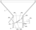
Fig. 1 is a schematic view of the utility model when the bottle cap needs to be guided.
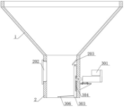
Fig. 2 is a schematic view of the utility model when the bottle cap is not required to be guided.
In the figure, 1-an upper cover bucket, 2-a cover-shifting bucket, 201-a discharge hole, 202-a cover plate, 203-a cover plate, 204-a containing groove, 3-a material guiding mechanism, 301-a thrust device, 302-a slide block, 303-a shifting plate, 304-a slide groove, 305-a hinged support and 306-a guide rod.
Detailed Description
To make the objects, technical solutions and advantages of the embodiments of the present invention clearer, the drawings of the embodiments of the present invention are combined to clearly and completely describe the technical solutions of the embodiments of the present invention, and obviously, the described embodiments are some embodiments of the present invention, not all embodiments. The components of embodiments of the present invention, as generally described and illustrated in the figures herein, may be arranged and designed in a wide variety of different configurations.
Thus, the following detailed description of the embodiments of the present invention, presented in the accompanying drawings, is not intended to limit the scope of the invention, as claimed, but is merely representative of selected embodiments of the invention. Based on the embodiments in the present invention, all other embodiments obtained by a person skilled in the art without creative work belong to the protection scope of the present invention.
In the present invention, the embodiments and the features of the embodiments may be combined with each other without conflict.
It should be noted that: like reference numbers and letters refer to like items in the following figures, and thus, once an item is defined in one figure, it need not be further defined and explained in subsequent figures.
In the description of the present invention, it should be noted that the terms "center", "upper", "lower", "left", "right", "vertical", "horizontal", "inner", "outer", and the like indicate the position or positional relationship based on the position or positional relationship shown in the drawings, or the position or positional relationship which the products of the present invention are conventionally placed in use, or the position or positional relationship which the skilled person conventionally understand, and are only for convenience of describing the present invention and simplifying the description, but do not indicate or imply that the device or element to which the reference is made must have a specific position, be constructed in a specific orientation, and be operated, and thus should not be construed as limiting the present invention. Furthermore, the terms "first," "second," and the like are used merely to distinguish one description from another, and are not to be construed as indicating or implying relative importance.
In the description of the present invention, it should also be noted that, unless otherwise explicitly specified or limited, the terms "disposed," "mounted," "connected," and "connected" are to be construed broadly, e.g., as meaning either a fixed connection, a removable connection, or an integral connection; can be mechanically or electrically connected; they may be connected directly or indirectly through intervening media, or they may be interconnected between two elements. The specific meaning of the above terms in the present invention can be understood in specific cases to those skilled in the art.
Example (b):
referring to the embodiment shown in fig. 1-2, an upper cover chute material guiding device includes an upper cover bucket 1, a cover-shifting bucket 2 adapted to the upper cover bucket 1 is fixedly communicated with the bottom of the upper cover bucket 1, a material outlet 201 is disposed on one side of the cover-shifting bucket 2, a material guiding mechanism 3 is disposed in the cover-shifting bucket 2, the material guiding mechanism 3 includes a shifting plate 303 adapted to the cover-shifting bucket 2, a thrust device 301 for pushing the shifting plate 303 to rotate is disposed on the other side of the cover-shifting bucket 2, and the thrust device 301 may be an electric push rod, a hydraulic rod, an air cylinder, or other thrust components.
The discharge port 201 is hinged with a cover plate 202 matched with the discharge port 201, the shifting plate 303 is provided with a guide rod 306 for pushing the cover plate 202, the guide rod 306 can rotate along with the shifting plate 303 when the shifting plate 303 rotates, the cover plate 202 is pushed open along with the rotation of the shifting plate 303, preparation is made for smooth guiding of the bottle cap, one end, far away from the shifting plate 303, of the guide rod 306 is in a spherical shape, friction force between the guide rod 306 and the cover plate 202 can be reduced, and the guide rod 306 and the spherical end are both arc surfaces, so that the bottle cap cannot be influenced to fall downwards.
Preferably, dial inside of lid fill 2 and be the sunshade 203 of slope form, and sunshade 203 is located the top of dialling board 303, and sunshade 203 can shelter from for dialling board 303, avoids the bottle lid to drop to the top surface of dialling board 303, and leads to dialling board 303 and receive the card when rotating and hinder.
Dial and be equipped with slide mechanism on the board 303, and slide mechanism is articulated mutually with thrust equipment 301, slide mechanism includes spout 304, the inside sliding connection of spout 304 has the slider 302 with spout 304 looks adaptation, be equipped with hinged-support 305 on the slider 302, and hinged-support 305 is connected with thrust equipment 301's output, this slide mechanism can be with the smooth rotation of dialling board 303 of turning into of horizontal motion, dial and still offer the groove 204 of accomodating that is used for accomodating hinged-support 305 on the lid fill 2, should accomodate the groove 204 and enable hinged-support 305 convenient storage, still incline and influence the bottle lid and drop when avoiding making to dial board 303 and retrieving.
The working process of the utility model is as follows: the capping machine can contain bottle caps in the capping bucket 1 and the cap-pulling bucket 2 under normal working conditions, when the bottle caps are used and the bottle caps in the capping machine need to be cleaned, the capping machine can be stopped, the thrust device 301 is started to enable the output end of the thrust device 301 to extend out, meanwhile, the pulling plate 303 can rotate around the rotating shaft of the thrust device 301 under the pushing action of the thrust device 301, when the pushing plate rotates, the bottle caps on the pushing plate can be forced to move upwards, when the output end of the thrust device 301 completely pushes out the pulling plate 303, namely, the pushing plate 303 rotates to the edge of the bottom surface of the discharge port 201, when the pulling plate 303 rotates, the guide rod 306 can simultaneously push the cover plate 202 to turn over, and when the pulling plate 303 completely locates, as shown in figure 1, the cover plate 202 is opened, because the pulling plate 303 is inclined, and the cover plate 202 is opened, the bottle caps above the pulling plate 303 automatically slide out from the discharge port 201, and when the bottle caps above completely slide out, the output end of the pushing device 301 is completely contracted, at this time, the shifting plate 303 is tightly attached to the inner wall of the cap-shifting hopper 2 in a vertical shape as shown in fig. 2, and a plurality of bottle caps possibly left on the bottom surface of the cap-shifting hopper 2 can be manually picked up.
Although the present invention has been described in detail with reference to the foregoing embodiments, it will be apparent to those skilled in the art that modifications may be made to the embodiments or portions thereof without departing from the spirit and scope of the invention.
Claims (7)
1. The utility model provides an upper cover groove guiding device, includes upper cover fill (1), its characterized in that: the bottom of the upper cover bucket (1) is fixedly communicated with a cover shifting bucket (2) matched with the upper cover bucket (1), a discharge hole (201) is formed in one side of the cover shifting bucket (2), a material guide mechanism (3) is arranged in the cover shifting bucket (2), the material guide mechanism (3) comprises a shifting plate (303) matched with the cover shifting bucket (2), and a pushing plate (303) rotating thrust device (301) is arranged on the other side of the cover shifting bucket (2).
2. The upper cover chute material guiding device as defined in claim 1, wherein: the discharge port (201) is hinged with a cover plate (202) matched with the discharge port (201), and the poking plate (303) is provided with a guide rod (306) for pushing the cover plate (202).
3. The upper cover chute material guiding device as defined in claim 1, wherein: the inner part of the cover-poking bucket (2) is provided with an inclined shielding plate (203), and the shielding plate (203) is positioned above the poking plate (303).
4. The upper cover chute material guiding device as defined in claim 1, wherein: the shifting plate (303) is provided with a sliding mechanism, and the sliding mechanism is hinged with the thrust equipment (301).
5. The upper cover chute material guiding device as defined in claim 4, wherein: the sliding mechanism comprises a sliding groove (304), a sliding block (302) matched with the sliding groove (304) is connected to the inside of the sliding groove (304) in a sliding mode, a hinged support (305) is arranged on the sliding block (302), and the hinged support (305) is connected with the output end of the thrust device (301).
6. The upper cover chute material guiding device as defined in claim 2, wherein: one end of the guide rod (306) far away from the shifting plate (303) is spherical.
7. The upper cover chute material guiding device as defined in claim 5, wherein: the cover-pulling bucket (2) is also provided with a containing groove (204) for containing a hinged support (305).
Priority Applications (1)
| Application Number | Priority Date | Filing Date | Title |
|---|---|---|---|
| CN202023184649.3U CN214059832U (en) | 2020-12-25 | 2020-12-25 | Upper cover groove guiding device |
Applications Claiming Priority (1)
| Application Number | Priority Date | Filing Date | Title |
|---|---|---|---|
| CN202023184649.3U CN214059832U (en) | 2020-12-25 | 2020-12-25 | Upper cover groove guiding device |
Publications (1)
| Publication Number | Publication Date |
|---|---|
| CN214059832U true CN214059832U (en) | 2021-08-27 |
Family
ID=77387228
Family Applications (1)
| Application Number | Title | Priority Date | Filing Date |
|---|---|---|---|
| CN202023184649.3U Active CN214059832U (en) | 2020-12-25 | 2020-12-25 | Upper cover groove guiding device |
Country Status (1)
| Country | Link |
|---|---|
| CN (1) | CN214059832U (en) |
Cited By (1)
| Publication number | Priority date | Publication date | Assignee | Title |
|---|---|---|---|---|
| CN114734488A (en) * | 2022-03-21 | 2022-07-12 | 谷实生物集团股份有限公司 | Processing device and processing technology of straw feed |
-
2020
- 2020-12-25 CN CN202023184649.3U patent/CN214059832U/en active Active
Cited By (1)
| Publication number | Priority date | Publication date | Assignee | Title |
|---|---|---|---|---|
| CN114734488A (en) * | 2022-03-21 | 2022-07-12 | 谷实生物集团股份有限公司 | Processing device and processing technology of straw feed |
Similar Documents
| Publication | Publication Date | Title |
|---|---|---|
| CN214059832U (en) | Upper cover groove guiding device | |
| CN213493997U (en) | A to rolling machine for material is broken | |
| CN209093816U (en) | A kind of 3D printing metal powder production efficient circulation screening system | |
| CN212799579U (en) | Filling equipment for shampoo production | |
| CN211520495U (en) | Aluminum powder storage tank convenient to ejection of compact | |
| CN210884326U (en) | Blowing machine convenient to material loading | |
| CN210175679U (en) | Waste battery classification recycling device | |
| CN207355414U (en) | Support device, draining device and equipment of squeezing the juice automatically | |
| CN218229497U (en) | Facial mask liquid quantitative filling device is used in facial mask production of whitening moisturizing | |
| CN215464118U (en) | Stirring barrel feeding device | |
| CN214502928U (en) | Material taking device for automobile bridge type sampling machine | |
| CN209567330U (en) | A kind of medicament reservoir | |
| CN215346977U (en) | Moon cake filling material processing is with pushing away filling area elevating gear | |
| CN210945513U (en) | Hydrorefining reaction unit for lubricating oil | |
| CN207843679U (en) | A kind of automatic energy saving packing jar for taking object | |
| CN207448635U (en) | A kind of drug mouth structure of machine for traditional Chinese medicinal material,table cutting | |
| CN212606748U (en) | Sealed storage box of sugar pearl for cake preparation | |
| CN210991829U (en) | Medicine bottle cap convenient for pouring tablets | |
| CN206549699U (en) | A kind of combined movable grain storing box body | |
| CN213523845U (en) | Tobacco crushing and canning machine | |
| CN211358752U (en) | Cooking pot capable of opening cover in labor-saving manner | |
| CN220616759U (en) | Rice seed storage device | |
| CN210823814U (en) | Garbage can with two opening ends sharing movable bottom | |
| CN213503710U (en) | Storage device for machining bearing outer sleeve | |
| CN215326870U (en) | Automatic gel filling machine |
Legal Events
| Date | Code | Title | Description |
|---|---|---|---|
| GR01 | Patent grant | ||
| GR01 | Patent grant |