CN214045959U - Wireless earphone and charging seat thereof - Google Patents
Wireless earphone and charging seat thereof Download PDFInfo
- Publication number
- CN214045959U CN214045959U CN202023275767.5U CN202023275767U CN214045959U CN 214045959 U CN214045959 U CN 214045959U CN 202023275767 U CN202023275767 U CN 202023275767U CN 214045959 U CN214045959 U CN 214045959U
- Authority
- CN
- China
- Prior art keywords
- earphone
- housing
- charging
- circuit board
- thimble
- Prior art date
- Legal status (The legal status is an assumption and is not a legal conclusion. Google has not performed a legal analysis and makes no representation as to the accuracy of the status listed.)
- Active
Links
Images


Abstract
The utility model discloses a wireless earphone and charging seat thereof, include: the earphone assembly comprises a first earphone main body and a second earphone main body, the charging assembly comprises a conducting strip, a battery and a charging circuit board, the battery and the charging circuit board are respectively arranged in the first earphone main body, the battery is electrically connected with the charging circuit board, the conducting strip is arranged at one end, away from the earphone connecting ring, of the first earphone main body, and the conducting strip is electrically connected with the charging circuit board. Through setting up the conducting strip, can be used for realizing the electricity with the box that charges and be connected, realize charging and supplying power to wireless earphone, and the conducting strip sets up in the one end that earphone go-between was kept away from to first earphone main part, and wireless earphone can vertically place to charge on the charging seat, avoids in a jumble, and the arrangement of being convenient for, the stability of charging is favorable to guaranteeing wireless earphone's normal use, improves wireless earphone's life, improves user's use satisfaction.
Description
Technical Field
The utility model relates to an earphone technical field especially relates to a wireless earphone and charging seat thereof.
Background
The wireless earphone is one kind of earphone, the line in the middle of the wireless earphone is replaced by the electric wave, be connected to the transmitting terminal from the audio frequency export of computer, again send to the earphone of receiving terminal through the electric wave by the transmitting terminal, and the receiving terminal is exactly equivalent to a radio, wireless earphone compares with wired earphone, it is not big to distinguish on tone quality, because the line in the middle of the wireless earphone is replaced by the electric wave, therefore, wireless comparison is convenient, receive more and more user's liking, current wireless earphone has three kinds, one is bluetooth earphone, two is infrared ray earphone, three is 2.4G, can supply different users to select according to own needs.
However, in the use of earphone, need charge to the earphone, thereby guarantee the power supply of earphone, guarantee the normal use of earphone, and traditional wireless earphone, realize charging through the power socket that uses the power cord to connect wireless earphone usually, when charging, wireless earphone and power cord are generally placed at will, the mixed and disorderly condition appears easily, be not convenient for arrange in order, occupy more space, and simultaneously, through charging many times, plug power cord many times, not hard up and contact failure's condition appears easily in wireless earphone's power socket, influence the going on of normally charging, thereby influence the normal use of wireless earphone, the life of wireless earphone has been reduced, and the power cord receives the bending and pulling in the use, also damage easily, need to change, cause puzzlement and inconvenience for the user.
SUMMERY OF THE UTILITY MODEL
The utility model aims at overcoming the weak point among the prior art, providing a wireless earphone and charging seat that simple structure and practicality are good, replacing the charge form of power cord, the arrangement of being convenient for, and the stability of charging is favorable to guaranteeing the normal use of wireless earphone, improves user's use satisfaction.
The purpose of the utility model is realized through the following technical scheme:
a wireless headset, comprising:
an earphone connecting ring;
the earphone assembly comprises a first earphone main body and a second earphone main body, and the first earphone main body and the second earphone main body are detachably connected with two ends of the earphone connecting ring respectively;
the earphone comprises a first earphone body, a charging assembly and a second earphone body, wherein the charging assembly comprises a conducting strip, a battery and a charging circuit board, the battery and the charging circuit board are respectively arranged in the first earphone body, the battery is electrically connected with the charging circuit board, the conducting strip is arranged at one end, far away from an earphone connecting ring, of the first earphone body, and the conducting strip is electrically connected with the charging circuit board.
In one embodiment, the first earphone main body comprises a first shell, a first connecting shell and a first horn, the first shell is detachably connected with one end of the earphone connecting ring, a supporting plate is arranged at the bottom of the first shell, the conducting strip is arranged on the supporting plate, an electrifying hole is formed in the bottom of the first shell, the first connecting shell is detachably connected with the first shell, a battery accommodating groove is formed in the first connecting shell, and the first horn is arranged on the first connecting shell.
In one embodiment, the first earphone body further comprises a first protection cover connected with the first connection housing.
In one embodiment, the second earphone main body includes a second housing detachably connected to the other end of the earphone connecting ring, a second connecting housing detachably connected to the second housing, and a second speaker disposed on the second connecting housing.
In one embodiment, the second earphone body further comprises a second protective sleeve connected with the second connection housing.
In one embodiment, one end of the earphone connecting ring is provided with a first supporting column, the first shell is provided with a first movable hole, and the first supporting column is arranged in the first shell through the first movable hole.
In one embodiment, the other end of the earphone connecting ring is provided with a second supporting column, the second casing is opened with a second moving hole, and the second supporting column is arranged in the second casing through the second moving hole.
The utility model also provides a charging seat for to above wireless earphone charge, include:
the shell comprises a bottom plate and a top cover, the top cover is detachably connected with the bottom plate, and a first through hole and a second through hole are formed in the top cover;
the power supply assembly comprises a power supply circuit board, a first connecting thimble and a second connecting thimble, the power supply circuit board is arranged on the bottom plate, the first connecting thimble and the second connecting thimble are respectively arranged on the top cover, the first connecting thimble and the second connecting thimble are respectively electrically connected with the power supply circuit board, the first connecting thimble is arranged in the first through hole in an exposed manner, the second connecting thimble is arranged in the second through hole in an exposed manner, and the second connecting thimble is arranged in the second through hole in an exposed manner.
In one embodiment, the charging stand further includes a connecting assembly, the connecting assembly includes a first mounting block and a second mounting block, the first mounting block and the second mounting block are detachably connected to the top cover, the first connecting pin is disposed on the first mounting block, and the second connecting pin is disposed on the second mounting block.
In one embodiment, the first mounting block is provided with a first spacer and the second mounting block is provided with a second spacer.
Compared with the prior art, the utility model discloses at least, following advantage has:
the utility model relates to a wireless earphone and box that charges thereof, through setting up the conducting strip, can be used for realizing the electricity with the box that charges and be connected, set up charging circuit board and battery, can realize circuit connection and control, the battery can be used for storing the electric energy and provide the electric energy, thereby realize charging and supplying power to wireless earphone, and the conducting strip sets up in the one end that earphone go-between was kept away from to first earphone main part, that is to say, the conducting strip sets up in the bottom of first earphone main part, wireless earphone can vertically place and charge on the charging seat, avoid in a jumble, be convenient for arrange in order, and charge stably, be favorable to guaranteeing wireless earphone's normal use, improve wireless earphone's life, user's use satisfaction is improved.
Drawings
In order to more clearly illustrate the technical solutions of the embodiments of the present invention, the drawings that are required to be used in the embodiments will be briefly described below, it should be understood that the following drawings only illustrate some embodiments of the present invention, and therefore should not be considered as limiting the scope, and for those skilled in the art, other related drawings can be obtained according to the drawings without inventive efforts.
Fig. 1 is a schematic structural diagram of a wireless headset according to an embodiment of the present invention;
fig. 2 is an exploded view of a first earphone main body of the wireless earphone according to an embodiment of the present invention;
fig. 3 is a schematic structural view of a first housing and a conductive sheet of a wireless headset according to an embodiment of the present invention;
fig. 4 is an exploded view of a second earphone main body of the wireless earphone according to an embodiment of the present invention;
fig. 5 is a schematic structural diagram of a charging seat according to an embodiment of the present invention.
Detailed Description
In order to facilitate understanding of the present invention, the present invention will be described more fully hereinafter with reference to the accompanying drawings. The preferred embodiments of the present invention are shown in the drawings. The invention may, however, be embodied in many different forms and should not be construed as limited to the embodiments set forth herein. Rather, these embodiments are provided so that this disclosure will be thorough and complete.
It will be understood that when an element is referred to as being "secured to" another element, it can be directly on the other element or intervening elements may also be present. When an element is referred to as being "connected" to another element, it can be directly connected to the other element or intervening elements may also be present. The terms "vertical," "horizontal," "left," "right," and the like as used herein are for illustrative purposes only and do not represent the only embodiments.
Unless defined otherwise, all technical and scientific terms used herein have the same meaning as commonly understood by one of ordinary skill in the art to which this invention belongs. The terminology used herein in the description of the invention is for the purpose of describing particular embodiments only and is not intended to be limiting of the invention. As used herein, the term "and/or" includes any and all combinations of one or more of the associated listed items.
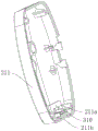
Referring to fig. 1, 2 and 4, the wireless headset 10 includes a headset coupling ring 100, a headset assembly 200 and a charging assembly. The earphone assembly 200 includes a first earphone body 210 and a second earphone body 220, and the first earphone body 210 and the second earphone body 220 are detachably connected to two ends of the earphone connecting ring 100, respectively. The charging assembly includes a conductive plate 310, a battery (not shown) and a charging circuit board 320, the battery and the charging circuit board 320 are respectively disposed in the first earphone main body 210, the battery is electrically connected to the charging circuit board 320, the conductive plate 310 is disposed at an end of the first earphone main body 210 away from the earphone connecting ring 100, and the conductive plate 310 is electrically connected to the charging circuit board 320.
It should be noted that the earphone connecting ring 100 is arc-shaped and is used for connecting the first earphone main body 210 and the second earphone main body 220, the first earphone main body 210 and the second earphone main body 220 are respectively used for clinging to the ears of a user and playing audio, the battery is disposed in the first earphone main body 210 for storing and providing electric energy and is electrically connected with the charging circuit board 320, the conductive plate 310 is disposed in the first earphone main body 210 and is electrically connected with the charging circuit board 320 for electrically connecting with an external charging device, i.e. electrically connected with the charging base, thereby realizing the electrical connection with the charging base, the charging of the battery is realized by the control of the charging circuit board 320, thereby realizing the charging of the wireless earphone 10, and the conductive plate 310 is disposed at one end of the first earphone main body 210 away from the earphone connecting ring 100, i.e. the conductive plate 310 is disposed at the bottom of the first earphone main body 210, the wireless earphone 10 can be vertically placed on the charging base for charging, avoid in a jumble, the arrangement of being convenient for, and under the action of gravity, conducting strip 310 can closely laminate with the charging seat, and the stability of charging is favorable to guaranteeing wireless earphone 10's normal use, improves wireless earphone 10's life, improves user's use satisfaction.
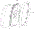
Specifically, referring to fig. 2 and 3, the first earphone main body 210 includes a first housing 211, a first connecting housing 212 and a first speaker 213, the first housing 211 is detachably connected to one end of the earphone connecting ring 100, a supporting plate 211a is disposed at the bottom of the first housing 211, the conductive plate 310 is disposed on the supporting plate 211a, a power-on hole 211b is disposed at the bottom of the first housing 211, the first connecting housing 212 is detachably connected to the first housing 211, the first connecting housing 212 is provided with a battery receiving groove 212a, and the first speaker 213 is disposed on the first connecting housing 212. It can be understood that the first housing 211 can be detachably connected to the earphone connecting ring 100 by a screw, the two conductive sheets 310 are respectively used for connecting the positive and negative electrodes of the charging seat, the bottom of the first housing 211 is provided with a power-on hole 211b, the conductive sheets 310 can be communicated with the outside, so as to achieve conductivity, similarly, the first connecting housing 212 can be detachably connected to the first housing 211 by a screw, the first connecting housing 212 is used for accommodating a battery by a battery accommodating groove 212a, and the first speaker 213 is disposed on the first connecting housing 212 and is used for outputting audio.
More specifically, referring to fig. 4, the second earphone main body 220 includes a second housing 221, a second connection housing 222 and a second speaker 223, the second housing 221 is detachably connected to the other end of the earphone connecting ring 100, the second connection housing 222 is detachably connected to the second housing 221, and the second speaker 223 is disposed on the second connection housing 222. It is understood that the second housing 221 may be detachably coupled to the earphone coupling ring 100 by means of a set screw, and likewise, the second connection housing 222 may be detachably coupled to the second housing 221 by means of a set screw, and the second speaker 223 is disposed on the second connection housing 222 and is used to realize the output of audio.
Further, referring to fig. 2 and 4, the first earphone main body 210 further includes a first protection cover 214, and the first protection cover 214 is connected to the first connection housing 212. The second earphone body 220 further includes a second protective cover 224, and the second protective cover 224 is connected to the second connection housing 222. It can be understood that by arranging the first protective sleeve 214 and the second protective sleeve 224, each component can be protected in a closed manner, and meanwhile, the ear of a user can be better fitted, so that the comfort level of the user is improved.
Further, referring to fig. 1, fig. 2 and fig. 4, a first supporting column 101 is disposed at one end of the earphone connecting ring 100, a first movable hole 211c is formed in the first housing 211, and the first supporting column 101 is disposed in the first housing 211 through the first movable hole 211 c. The other end of the earphone connecting ring 100 is provided with a second supporting pole 102, the second casing 221 is provided with a second movable hole 221a, and the second supporting pole 102 is arranged in the second casing 221 through the second movable hole 221 a. It can be understood that, by arranging the first supporting column 101 and the second supporting column 102 and respectively inserting the first supporting column 101 and the second supporting column 102 into the first casing 211 and the second casing 221, the positioning and installation can be further realized, and meanwhile, the first supporting column 101 and the second supporting column 102 can play a supporting role, which is beneficial to further improving the structural stability of the wireless headset 10.
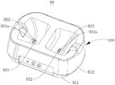
Referring to fig. 5, the present invention further provides a charging stand 90 for charging the wireless earphone 10, including: a housing 910 and a power supply assembly 920. The housing 910 includes a bottom plate 911 and a top cover 912, the top cover 912 is detachably connected to the bottom plate 911, and the top cover 912 has a first through hole and a second through hole. Power supply unit 920 includes power supply circuit board (not shown), first connection thimble 922 and second connection thimble 923, power supply circuit board set up in on the bottom plate 911, first connection thimble 922 reaches second connection thimble 923 install respectively in on the top cap 912, first connection thimble 922 reaches second connection thimble 923 respectively with the power supply circuit board electricity is connected, first connection thimble 922 wears to locate first through-hole, just first connection thimble 922 dew is arranged in outside the first through-hole, second connection thimble 923 wears to locate the second through-hole, just second connection thimble 923 dew is arranged in outside the second through-hole.
It should be noted that, the cavity structure is formed after the bottom plate 911 and the top cover 912 are covered with each other, the power supply circuit board is disposed on the bottom plate 911, the power supply circuit board is used for controlling a circuit, the first connection thimble 922 and the second connection thimble 923 are respectively electrically connected with the power supply circuit board, the power supply circuit board is used for being connected with the conducting strip 310, charging is realized, the first connection thimble 922 and the second connection thimble 923 are arranged on the top cover 912 relatively in a left-right direction, and therefore electrical connection with the conducting strip 310 can be realized, that is, the conducting strip 310 of the wireless earphone 10 can be placed randomly in a left-right direction, and can be electrically connected with the first connection thimble 922 or the second connection thimble 923, so that charging is realized, the applicability is good, convenience in use is facilitated, and convenience in use is improved.
Specifically, referring to fig. 5, the charging stand 90 further includes a connecting assembly, the connecting assembly includes a first mounting block 931 and a second mounting block 932, the first mounting block 931 and the second mounting block 932 are detachably connected to the top cover 912 respectively, the first connecting pin 922 is disposed on the first mounting block 931, and the second connecting pin 923 is disposed on the second mounting block 932. It can be understood that, through setting up first installation piece 931 and second installation piece 932, can be used for installing first thimble 922 and the second thimble 923 of connecting respectively, first installation piece 931 and second mounting hole are through seting up the mounting hole to can install first thimble 922 and the second thimble 923 of connecting on first installation piece 931 and second installation piece 932, simple to operate.
Further, referring to fig. 5, the first mounting block 931 is provided with a first spacer 931a, and the second mounting block 932 is provided with a second spacer 932 a. It can be understood that, through setting up first spacer 931a and second spacer 932a, can play the shelves effect of separating, further avoid appearing the short circuit phenomenon, improve the security of charging.
Compared with the prior art, the utility model discloses at least, following advantage has:
the utility model relates to a wireless earphone and box that charges thereof, through setting up the conducting strip, can be used for realizing the electricity with the box that charges and be connected, set up charging circuit board and battery, can realize circuit connection and control, the battery can be used for storing the electric energy and provide the electric energy, thereby realize charging and supplying power to wireless earphone, and the conducting strip sets up in the one end that earphone go-between was kept away from to first earphone main part, that is to say, the conducting strip sets up in the bottom of first earphone main part, wireless earphone can vertically place and charge on the charging seat, avoid in a jumble, be convenient for arrange in order, and charge stably, be favorable to guaranteeing wireless earphone's normal use, improve user's use satisfaction.
The above-mentioned embodiments only represent some embodiments of the present invention, and the description thereof is specific and detailed, but not to be construed as limiting the scope of the present invention. It should be noted that, for those skilled in the art, without departing from the spirit of the present invention, several variations and modifications can be made, which are within the scope of the present invention. Therefore, the protection scope of the present invention should be subject to the appended claims.
Claims (10)
1. A wireless headset, comprising:
an earphone connecting ring;
the earphone assembly comprises a first earphone main body and a second earphone main body, and the first earphone main body and the second earphone main body are detachably connected with two ends of the earphone connecting ring respectively;
the earphone comprises a first earphone body, a charging assembly and a second earphone body, wherein the charging assembly comprises a conducting strip, a battery and a charging circuit board, the battery and the charging circuit board are respectively arranged in the first earphone body, the battery is electrically connected with the charging circuit board, the conducting strip is arranged at one end, far away from an earphone connecting ring, of the first earphone body, and the conducting strip is electrically connected with the charging circuit board.
2. The wireless earphone according to claim 1, wherein the first earphone main body comprises a first housing, a first connecting housing and a first speaker, the first housing is detachably connected to one end of the earphone connecting ring, a supporting plate is disposed at the bottom of the first housing, the conductive plate is disposed on the supporting plate, an electrical through hole is disposed at the bottom of the first housing, the first connecting housing is detachably connected to the first housing, the first connecting housing is provided with a battery accommodating groove, and the first speaker is disposed on the first connecting housing.
3. The wireless headset of claim 2, wherein the first headset body further comprises a first protective sleeve, the first protective sleeve being connected with the first connection housing.
4. The wireless earphone according to claim 3, wherein the second earphone main body comprises a second housing, a second connecting shell and a second speaker, the second housing is detachably connected with the other end of the earphone connecting ring, the second connecting shell is detachably connected with the second housing, and the second speaker is disposed on the second connecting shell.
5. The wireless headset of claim 4, wherein the second headset body further comprises a second protective sleeve, the second protective sleeve being connected with the second connection housing.
6. The wireless earphone according to claim 5, wherein one end of the earphone connecting ring is provided with a first supporting pillar, the first housing is opened with a first movable hole, and the first supporting pillar is arranged in the first housing through the first movable hole.
7. The wireless earphone according to claim 5, wherein the other end of the earphone connecting ring is provided with a second supporting column, the second casing is opened with a second moving hole, and the second supporting column is arranged in the second casing through the second moving hole.
8. A charging stand for charging the wireless headset of any one of claims 1 to 7, comprising:
the shell comprises a bottom plate and a top cover, the top cover is detachably connected with the bottom plate, and a first through hole and a second through hole are formed in the top cover;
the power supply assembly comprises a power supply circuit board, a first connecting thimble and a second connecting thimble, the power supply circuit board is arranged on the bottom plate, the first connecting thimble and the second connecting thimble are respectively arranged on the top cover, the first connecting thimble and the second connecting thimble are respectively electrically connected with the power supply circuit board, the first connecting thimble is arranged in the first through hole in an exposed manner, the second connecting thimble is arranged in the second through hole in an exposed manner, and the second connecting thimble is arranged in the second through hole in an exposed manner.
9. The charging stand of claim 8, further comprising a connecting assembly, wherein the connecting assembly comprises a first mounting block and a second mounting block, the first mounting block and the second mounting block are detachably connected to the top cover, the first connecting pin is disposed on the first mounting block, and the second connecting pin is disposed on the second mounting block.
10. The charging dock of claim 9, wherein the first mounting block is provided with a first spacer and the second mounting block is provided with a second spacer.
Priority Applications (1)
| Application Number | Priority Date | Filing Date | Title |
|---|---|---|---|
| CN202023275767.5U CN214045959U (en) | 2020-12-28 | 2020-12-28 | Wireless earphone and charging seat thereof |
Applications Claiming Priority (1)
| Application Number | Priority Date | Filing Date | Title |
|---|---|---|---|
| CN202023275767.5U CN214045959U (en) | 2020-12-28 | 2020-12-28 | Wireless earphone and charging seat thereof |
Publications (1)
| Publication Number | Publication Date |
|---|---|
| CN214045959U true CN214045959U (en) | 2021-08-24 |
Family
ID=77343588
Family Applications (1)
| Application Number | Title | Priority Date | Filing Date |
|---|---|---|---|
| CN202023275767.5U Active CN214045959U (en) | 2020-12-28 | 2020-12-28 | Wireless earphone and charging seat thereof |
Country Status (1)
| Country | Link |
|---|---|
| CN (1) | CN214045959U (en) |
-
2020
- 2020-12-28 CN CN202023275767.5U patent/CN214045959U/en active Active
Similar Documents
| Publication | Publication Date | Title |
|---|---|---|
| CN102123333A (en) | Headset and portable electronic device using same | |
| CN207505089U (en) | A kind of line control earphone stores charging box | |
| CN208029056U (en) | A kind of wireless headset of Band clamp charging base | |
| JP3143554U (en) | Storage type portable charging adapter | |
| CN214045959U (en) | Wireless earphone and charging seat thereof | |
| CN209184774U (en) | A kind of headphone charging system | |
| CN209948729U (en) | Charging matching positioning device of wireless earphone | |
| CN217904629U (en) | Neck hanging type Bluetooth earphone | |
| CN111628578A (en) | Multifunctional Bluetooth headset charging device | |
| CN207819517U (en) | A kind of bluetooth headset wireless charging device | |
| CN213368111U (en) | Bluetooth temperature measurement earphone that signal penetrability is strong | |
| CN212486139U (en) | Mobile power supply with Bluetooth sound box | |
| CN212752611U (en) | Bluetooth headset receiver | |
| CN210839027U (en) | Square ear-hanging type touch wireless Bluetooth earphone charging seat | |
| CN209896742U (en) | Separated vehicle-mounted charger | |
| CN105892579A (en) | Multifunctional keyboard and display device | |
| CN211606166U (en) | Mobile power supply capable of charging Bluetooth headset | |
| CN109587595A (en) | A kind of headphone charging system | |
| CN219419774U (en) | Dustproof USB wireless charging socket | |
| CN217544833U (en) | Battery detachable treasured that charges | |
| CN213244316U (en) | Wireless earphone receiver | |
| CN210839026U (en) | Wireless touch Bluetooth headset charging seat with mobile charging function | |
| CN217335869U (en) | Multifunctional earphone | |
| CN216287053U (en) | Bluetooth game mobile phone protective housing | |
| CN218771330U (en) | Charger baby |
Legal Events
| Date | Code | Title | Description |
|---|---|---|---|
| GR01 | Patent grant | ||
| GR01 | Patent grant |