CN214045502U - Saddle-shaped cable net flexible photovoltaic system - Google Patents
Saddle-shaped cable net flexible photovoltaic system Download PDFInfo
- Publication number
- CN214045502U CN214045502U CN202023207543.0U CN202023207543U CN214045502U CN 214045502 U CN214045502 U CN 214045502U CN 202023207543 U CN202023207543 U CN 202023207543U CN 214045502 U CN214045502 U CN 214045502U
- Authority
- CN
- China
- Prior art keywords
- cable
- shaped
- saddle
- bearing
- steel
- Prior art date
- Legal status (The legal status is an assumption and is not a legal conclusion. Google has not performed a legal analysis and makes no representation as to the accuracy of the status listed.)
- Active
Links
Images


Classifications
-
- Y—GENERAL TAGGING OF NEW TECHNOLOGICAL DEVELOPMENTS; GENERAL TAGGING OF CROSS-SECTIONAL TECHNOLOGIES SPANNING OVER SEVERAL SECTIONS OF THE IPC; TECHNICAL SUBJECTS COVERED BY FORMER USPC CROSS-REFERENCE ART COLLECTIONS [XRACs] AND DIGESTS
- Y02—TECHNOLOGIES OR APPLICATIONS FOR MITIGATION OR ADAPTATION AGAINST CLIMATE CHANGE
- Y02E—REDUCTION OF GREENHOUSE GAS [GHG] EMISSIONS, RELATED TO ENERGY GENERATION, TRANSMISSION OR DISTRIBUTION
- Y02E10/00—Energy generation through renewable energy sources
- Y02E10/50—Photovoltaic [PV] energy
Abstract
The utility model discloses a saddle-shaped cable net flexible photovoltaic system, which comprises a photovoltaic component and a saddle-shaped cable net flexible support used for supporting the photovoltaic component, wherein the saddle-shaped cable net flexible support mainly comprises a peripheral steel frame structure and a stabilizing cable and a bearing cable which are arranged in the peripheral steel frame structure in a criss-cross manner and used for installing the photovoltaic component; the peripheral steel frame structure mainly comprises a parabolic steel beam and a support column arranged at the bottom of the parabolic steel beam, wherein a stay cable is arranged on the outer side wall of the support column, one end of the stay cable is connected with the support column, and the other end of the stay cable is anchored on the ground; the photovoltaic component is arranged on the bearing cable through a component frame, and the stabilizing cable and the bearing cable are connected in a cross manner and form a stable saddle-shaped curved surface under the supporting action of a peripheral steel frame structure; the joint of the stabilizing cable and the bearing cable is fixed through a node bottom plate and a U-shaped bolt.
Description
Technical Field
The utility model relates to a photovoltaic power generation equipment field, concretely relates to flexible photovoltaic system of shape of a saddle cable net.
Background
Due to the continuous aggravation of the problems of energy exhaustion and environmental pollution, renewable clean energy represented by solar energy is gradually paid attention to and promotes the continuous development of global energy transformation, and solar energy can be directly converted into electric energy by using a photovoltaic power generation system. In engineering, a photovoltaic power station generally comprises a photovoltaic module, a photovoltaic bracket, a box transformer substation and other electrical equipment, wherein the photovoltaic bracket is a special bracket for mounting the photovoltaic module and is mainly of a steel structure and an aluminum alloy structure. Traditional rigidity photovoltaic support includes components such as sloping, purlin, stand, vaulting pole, and the installation place mainly lies in building roof and spacious ground, and structural foundation generally adopts forms such as bored concrete pile, steel spiral pile and bar foundation. At present, scholars at home and abroad research the design method, mechanical property, wind load effect and other contents of the rigid photovoltaic bracket and obtain corresponding achievements.
With the increasing shortage of available roof resources and high-quality land resources, the development of the traditional rigid photovoltaic support is gradually limited due to the wide floor space, high requirement on the flatness of the field and the like. In order to expand the space adaptability of the photovoltaic support, the component can be erected in the air by utilizing a large-span support system. Therefore, the limitation of the terrain condition caused by the landing of the conventional support can be avoided, and the continuous use of the original site can be ensured. The large-span support also provides a new direction for the future development of the photovoltaic market.
The flexible prestressed cable structural system is the most efficient large-span space structural system at present, and is widely applied to the field of large public buildings such as stadiums, exhibition halls and airports due to the typical characteristics of attractive appearance, light form and excellent performance. The structural system takes the inhaul cable as a core component, and the integral rigidity of the structure is established based on the prestress introduced by construction tensioning, so that the structural system can resist deformation caused by load and maintain the self stability of the structure. Therefore, it may be considered to design a flexible photovoltaic support based on a flexible prestressed cable structural system. Compared with a rigid support, the flexible support has the advantages of small steel consumption, low requirement on site foundation, wide application to various complex terrain conditions and the like. At present, a few flexible supports which are already put into use in engineering still mainly adopt a pure suspension cable structure system, namely, a photovoltaic module is directly laid on two parallel stay cables. The rigidity of the suspension cable structure outside the plane is weak, so that the vertical deformation of the structure is difficult to control, and particularly when the suspension cable structure is greatly influenced by typhoon in coastal areas, the support is easy to vibrate violently under the action of wind load, so that the photovoltaic module is damaged due to hidden cracking. Therefore, there is still a need for further improvement in the structural design for flexible stents.
Disclosure of Invention
The to-be-solved technical problem of the utility model lies in, to the above-mentioned defect of prior art, a can realize great span and the flexible photovoltaic system of saddle shape cable net of stronger stability is provided.
The utility model aims at providing a saddle-shaped cable net flexible photovoltaic system, which mainly comprises a photovoltaic component and a saddle-shaped cable net flexible support for supporting the photovoltaic component, wherein the saddle-shaped cable net flexible support mainly comprises a peripheral steel frame structure and a stabilizing cable and a bearing cable which are arranged in the peripheral steel frame structure in a criss-cross manner and used for mounting the photovoltaic component; the peripheral steel frame structure mainly comprises a parabolic steel beam and a support column arranged at the bottom of the parabolic steel beam, wherein a stay cable is arranged on the outer side wall of the support column, one end of the stay cable is connected with the support column, and the other end of the stay cable is anchored on the ground; the photovoltaic module is characterized in that the stabilizing cable is a single longitudinally-arranged inhaul cable, the bearing cable is two inhaul cables which are transversely arranged in parallel, the photovoltaic module is arranged on the bearing cable through a module frame, and the stabilizing cable and the bearing cable are connected in a cross mode and form a stable saddle-shaped curved surface under the supporting action of the peripheral steel frame structure.
Furthermore, the cross connection node of the stabilizing cable and the bearing cable is fixed through a node bottom plate and a U-shaped bolt, an arc-shaped groove is formed in the top of the node bottom plate along the length direction of the bearing cable, mounting holes for mounting the U-shaped bolt are respectively arranged on the end faces, close to the arc-shaped groove, of the node bottom plate in a penetrating mode, the bearing cable is arranged in the arc-shaped groove between the two U-shaped bolts, the stabilizing cable is arranged on the upper side of the bearing cable to be beneficial to maintaining the stability of the relative position, and the opening side of the U-shaped bolt penetrates through the mounting holes in the stabilizing cable and the node bottom plate and is arranged on the node bottom plate through double nuts.
Furthermore, the bottom of the component frame is provided with a U-shaped clamp, the component frame is arranged on the bearing cable through the U-shaped clamp, the U-shaped clamp comprises a U-shaped bolt and a clamp connecting piece arranged on the connecting end face of the U-shaped bolt and the component frame, and the bottom of the clamp connecting piece is provided with an arc-shaped groove used for fixing the bearing cable.
Furthermore, the inhaul cable of the stabilizing cable and the bearing cable is a stainless steel wire rope, a pressing screw rod is arranged at one end of the inhaul cable, a pressing cable head is arranged at the other end of the inhaul cable, the inhaul cable is connected with the inhaul cable through a tensioning sleeve with an internal thread, the inhaul cable is connected with the parabolic steel beam through an end anchor, the end anchor comprises a double-lug plate and a pin bolt, and the pressing cable head of the inhaul cable is hinged to the double-lug plate through the pin bolt.
Further, the support column includes the V font steel batter post of setting in vertical parabola shape girder steel bottom and sets up the vertical steel stand in horizontal parabola shape girder steel bottom.
Furthermore, the parabolic steel beam, the V-shaped steel inclined column and the vertical steel upright column are all H-shaped steel or square steel tubes.
The utility model has the advantages of: the utility model provides a photovoltaic system is based on saddle cable net structural style, and the geometric rigidity that the elastic rigidity that utilizes the component material to provide and cable prestressing force provide resists the deformation that the outer load arouses jointly, makes it can realize great span and possess stronger stability, and is stable firm between each connected node, can effectively improve photovoltaic system's life, has reduced manufacturing cost and maintenance cost.
Drawings
Fig. 1 is a schematic view of the overall structure of the present invention;
FIG. 2 is a schematic structural view of the cross-connecting joint of the stabilizing cable and the bearing cable of the present invention;
fig. 3 is a schematic structural view of the assembly frame of the present invention;
fig. 4 is a schematic structural view of the inhaul cable pressing screw rod end of the utility model;
fig. 5 is a schematic view of the connection structure of the head end of the inhaul cable pressing cable of the present invention.
Detailed Description
To make the objects, technical solutions and advantages of the present invention more clearly understood by those skilled in the art, the present invention will be further described with reference to the accompanying drawings and examples.
In the description of the present invention, it should be understood that the directions or positional relationships indicated by the terms "upper", "lower", "left", "right", "inner", "outer", "lateral", "vertical", and the like are the directions or positional relationships shown in the drawings, and are only for convenience of description of the present invention, and do not indicate or imply that the device or element referred to must have a specific direction, and therefore, should not be construed as limiting the present invention.
As shown in fig. 1-5, the saddle-shaped cable net flexible photovoltaic system of the present invention mainly includes a photovoltaic module 1 and a saddle-shaped cable net flexible support for supporting the photovoltaic module 1, wherein the saddle-shaped cable net flexible support mainly includes a peripheral steel frame structure 2 and a stabilizing cable 3 and a bearing cable 4, which are criss-cross arranged in the peripheral steel frame structure 2 for installing the photovoltaic module 1; the peripheral steel frame structure 2 mainly comprises a parabolic steel beam 5 and a support column arranged at the bottom of the parabolic steel beam 5, wherein a stay cable 6 is arranged on the outer side wall of the support column, one end of the stay cable 6 is connected with the support column, and the other end of the stay cable is anchored on the ground; the parabolic steel beam 5 is an approximate parabola formed by fitting a plurality of sections of broken lines, the stabilizing cable 3 is a single cable which is longitudinally arranged, the bearing cable 4 is two cables which are transversely arranged in parallel, the photovoltaic module 1 is arranged on the bearing cable 4 through a module frame 7, the stabilizing cable 3 and the bearing cable 4 are connected in a cross mode and form a stable saddle-shaped curved surface under the supporting effect of the peripheral steel frame structure 2, the shape and the prestress distribution of a cable net are determined by structural shape finding analysis, and the shape finding analysis can adopt a dynamic relaxation method or a force density method.
Referring to fig. 2, the cross-connection node of the stabilizing cable 3 and the bearing cable 4 is fixed through a node bottom plate 8 and a U-shaped bolt 9, an arc-shaped groove is formed in the top of the node bottom plate 8 along the length direction of the bearing cable 4, mounting holes for mounting the U-shaped bolts 9 are respectively arranged on the end faces of the two sides, close to the arc-shaped groove, of the node bottom plate 8, the bearing cable 4 is arranged in the arc-shaped groove between the two U-shaped bolts 9, the stabilizing cable 3 is arranged on the upper side of the bearing cable 4 so as to be beneficial to maintaining the stability of the relative position, and the opening side of the U-shaped bolt 9 penetrates through the mounting holes in the stabilizing cable 3 and the node bottom plate 8 and is arranged on the node bottom plate 8 through double nuts.
Referring to fig. 3, a U-shaped chuck 10 is arranged at the bottom of the component frame 7, the component frame 7 is arranged on the bearing cable 4 through the U-shaped chuck 10, the U-shaped chuck 10 comprises a U-shaped bolt and a chuck connecting piece arranged on the connecting end surface of the U-shaped bolt and the component frame, an arc-shaped groove for fixing the bearing cable is arranged at the bottom of the chuck connecting piece, the U-shaped chuck 10 is made of stainless steel, and the component frame 7 is made of aluminum alloy.
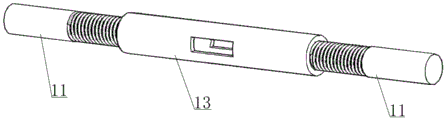
Referring to fig. 4-5, the stay cables of the stabilizing cable 3 and the bearing cable 4 are all stainless steel wire ropes, one end of each stay cable is provided with a pressing screw rod 11, the other end of each stay cable is provided with a pressing cable head 12, the pressing screw rods 11 between the stay cables are connected through tensioning sleeves 13 with internal threads, each tensioning sleeve 13 is a circular tube with a hole in the middle and reverse internal threads reserved at two ends, the stay cables are connected with the parabolic steel beams 5 through end anchors, each end anchor comprises a double-lug plate 14 and a pin bolt 15, and the pressing cable heads 12 of the stay cables are hinged to the double-lug plates 14 through the pin bolts 16.
Referring to fig. 1, the support column includes a V-shaped steel inclined column 17 disposed at the bottom of the longitudinal parabolic steel beam 5 and a vertical steel upright column 18 disposed at the bottom of the transverse parabolic steel beam 5. The parabolic steel beam 5, the V-shaped steel inclined column 17 and the vertical steel upright column 18 are all H-shaped steel or square steel tubes. The parabolic shape of the steel beam is determined by the span L, the midspan sag f and the height difference C of the supports at the two ends. The parabola abscissa is x, the corresponding rise is z, and the parabola equation is:

the specific embodiments described herein are merely illustrative of the principles of the present invention and its efficacy, and are not intended to limit the invention. Modifications and variations can be made to the above-described embodiments by those skilled in the art without departing from the spirit and scope of the present invention. Therefore, it is intended that all equivalent modifications or changes which can be made by those skilled in the art without departing from the spirit and technical idea of the present invention shall be covered by the claims of the present invention.
Claims (6)
1. Saddle shape cable net flexible photovoltaic system, its characterized in that: the saddle-shaped cable net flexible support mainly comprises a peripheral steel frame structure and stabilizing cables and bearing cables which are arranged in the peripheral steel frame structure in a criss-cross mode and used for mounting the photovoltaic modules; the peripheral steel frame structure mainly comprises a parabolic steel beam and a support column arranged at the bottom of the parabolic steel beam, wherein a stay cable is arranged on the outer side wall of the support column, one end of the stay cable is connected with the support column, and the other end of the stay cable is anchored on the ground; the photovoltaic module is characterized in that the stabilizing cable is a single longitudinally-arranged inhaul cable, the bearing cable is two inhaul cables which are transversely arranged in parallel, the photovoltaic module is arranged on the bearing cable through a module frame, and the stabilizing cable and the bearing cable are connected in a cross mode and form a stable saddle-shaped curved surface under the supporting action of the peripheral steel frame structure.
2. The saddle-shaped cable mesh flexible photovoltaic system of claim 1, wherein: the cross connection node of stabilizing cable and bearing cable fixes through node bottom plate and U-shaped bolt, the arc wall has been seted up along the length direction of bearing cable in the top of node bottom plate, and the node bottom plate wears to be equipped with the mounting hole that is used for installing the U-shaped bolt on being close to the both sides terminal surface of arc wall respectively, the bearing cable sets up in the arc wall between two U-shaped bolts, stabilizing cable sets up in the upside of bearing cable in order to do benefit to maintain relative position stable, the opening side of U-shaped bolt passes the mounting hole on stabilizing cable and the node bottom plate and is in through two nut settings on the node bottom plate.
3. The saddle-shaped cable mesh flexible photovoltaic system of claim 2, wherein: the bottom of the assembly frame is provided with a U-shaped clamp, the assembly frame is arranged on the bearing cable through the U-shaped clamp, the U-shaped clamp comprises a U-shaped bolt and a clamp connecting piece arranged on the connecting end face of the U-shaped bolt and the assembly frame, and the bottom of the clamp connecting piece is provided with an arc-shaped groove used for fixing the bearing cable.
4. The saddle-shaped cable mesh flexible photovoltaic system according to claim 2 or 3, characterized in that: the stay cable of the stabilizing cable and the bearing cable is a stainless steel wire rope, a pressing screw rod is arranged at one end of the stay cable, a pressing cable head is arranged at the other end of the stay cable, the stay cable is connected with the stay cable through a tensioning sleeve with an internal thread, the stay cable is connected with the parabolic steel beam through an end anchor, the end anchor comprises a double-lug plate and a pin bolt, and the pressing cable head of the stay cable is hinged to the double-lug plate through the pin bolt.
5. The saddle-shaped cable mesh flexible photovoltaic system of claim 4, wherein: the support column comprises a V-shaped steel inclined column arranged at the bottom of the longitudinal parabolic steel beam and a vertical steel upright column arranged at the bottom of the transverse parabolic steel beam.
6. The saddle-shaped cable mesh flexible photovoltaic system of claim 5, wherein: the parabolic steel beam, the V-shaped steel inclined column and the vertical steel upright column are all H-shaped steel or square steel tubes.
Priority Applications (1)
| Application Number | Priority Date | Filing Date | Title |
|---|---|---|---|
| CN202023207543.0U CN214045502U (en) | 2020-12-28 | 2020-12-28 | Saddle-shaped cable net flexible photovoltaic system |
Applications Claiming Priority (1)
| Application Number | Priority Date | Filing Date | Title |
|---|---|---|---|
| CN202023207543.0U CN214045502U (en) | 2020-12-28 | 2020-12-28 | Saddle-shaped cable net flexible photovoltaic system |
Publications (1)
| Publication Number | Publication Date |
|---|---|
| CN214045502U true CN214045502U (en) | 2021-08-24 |
Family
ID=77342634
Family Applications (1)
| Application Number | Title | Priority Date | Filing Date |
|---|---|---|---|
| CN202023207543.0U Active CN214045502U (en) | 2020-12-28 | 2020-12-28 | Saddle-shaped cable net flexible photovoltaic system |
Country Status (1)
| Country | Link |
|---|---|
| CN (1) | CN214045502U (en) |
Cited By (3)
| Publication number | Priority date | Publication date | Assignee | Title |
|---|---|---|---|---|
| CN113676119A (en) * | 2021-10-25 | 2021-11-19 | 深圳市安泰科能源环保股份有限公司 | Photovoltaic flexible support |
| CN114257164A (en) * | 2021-11-24 | 2022-03-29 | 一道新能源科技(衢州)有限公司 | Flexible photovoltaic system and method for monitoring tension of flexible part |
| CN117081489A (en) * | 2023-08-25 | 2023-11-17 | 哈尔滨工业大学 | Large-span fish belly type single-layer tracking type flexible photovoltaic bracket system |
-
2020
- 2020-12-28 CN CN202023207543.0U patent/CN214045502U/en active Active
Cited By (5)
| Publication number | Priority date | Publication date | Assignee | Title |
|---|---|---|---|---|
| CN113676119A (en) * | 2021-10-25 | 2021-11-19 | 深圳市安泰科能源环保股份有限公司 | Photovoltaic flexible support |
| CN113676119B (en) * | 2021-10-25 | 2022-02-08 | 深圳市安泰科能源环保股份有限公司 | Photovoltaic flexible support |
| CN114257164A (en) * | 2021-11-24 | 2022-03-29 | 一道新能源科技(衢州)有限公司 | Flexible photovoltaic system and method for monitoring tension of flexible part |
| CN114257164B (en) * | 2021-11-24 | 2022-09-27 | 一道新能源科技(衢州)有限公司 | Flexible photovoltaic system and method for monitoring tension of flexible part |
| CN117081489A (en) * | 2023-08-25 | 2023-11-17 | 哈尔滨工业大学 | Large-span fish belly type single-layer tracking type flexible photovoltaic bracket system |
Similar Documents
| Publication | Publication Date | Title |
|---|---|---|
| CN214045502U (en) | Saddle-shaped cable net flexible photovoltaic system | |
| CN112564594A (en) | Saddle-shaped cable net flexible photovoltaic system | |
| CN108365799B (en) | Suspension type flexible photovoltaic support unit and photovoltaic support | |
| CN218387334U (en) | Four-stay-rod type flexible photovoltaic support supporting structure | |
| CN114421868B (en) | From anchor formula polygon photovoltaic mounting system | |
| CN216599481U (en) | Large-span small-deformation flexible photovoltaic support system | |
| CN202039377U (en) | Prestressed steel stranded wire-combined anchor bolt | |
| CN210007646U (en) | wind-resistant stable large-span photovoltaic supporting structure | |
| CN218940983U (en) | Bidirectional cable photovoltaic system | |
| CN218449934U (en) | Windproof flexible photovoltaic support | |
| KR102455356B1 (en) | Anchor bolt installation device for solar panel installation | |
| CN114598248A (en) | Novel space cable net photovoltaic support system | |
| CN114337501A (en) | Arch flexible photovoltaic supporting structure who supports | |
| CN111677118A (en) | Steel-aluminum alloy composite structure system | |
| CN215498808U (en) | Vertical string solar photovoltaic support | |
| CN219164468U (en) | Flexible photovoltaic bracket system with three-cable-connected structure | |
| CN216810655U (en) | Roof waterproof engineering structure applied to assembly type building engineering | |
| CN216751595U (en) | Prestressed cable photovoltaic supporting structure | |
| CN111622576A (en) | High-strength metal electric power tower structure and erection method | |
| CN220544896U (en) | Novel photovoltaic large-span grid support structure | |
| CN108599681A (en) | A kind of solar power generation stent system suitable for fishing light complementation | |
| CN220754686U (en) | Photovoltaic supporting system | |
| CN216108587U (en) | Pile foundation fixing device | |
| CN212427531U (en) | Steel-aluminum alloy composite structure system | |
| CN217115982U (en) | Novel space cable net photovoltaic support system |
Legal Events
| Date | Code | Title | Description |
|---|---|---|---|
| GR01 | Patent grant | ||
| GR01 | Patent grant |