CN214036288U - Sound insulation device of high-pressure air blower - Google Patents
Sound insulation device of high-pressure air blower Download PDFInfo
- Publication number
- CN214036288U CN214036288U CN202023248045.0U CN202023248045U CN214036288U CN 214036288 U CN214036288 U CN 214036288U CN 202023248045 U CN202023248045 U CN 202023248045U CN 214036288 U CN214036288 U CN 214036288U
- Authority
- CN
- China
- Prior art keywords
- fixedly connected
- box body
- high pressure
- supporting plate
- supporting block
- Prior art date
- Legal status (The legal status is an assumption and is not a legal conclusion. Google has not performed a legal analysis and makes no representation as to the accuracy of the status listed.)
- Active
Links
Images


Abstract
The utility model discloses a high pressure blower's noise insulation, its technical scheme is: the power distribution box comprises a box body, the inside backup pad that is equipped with of box, backup pad top fixedly connected with air-blower body, the backup pad bottom is equipped with movable damping subassembly, movable damping subassembly includes supporting shoe and damping spring, supporting shoe and backup pad bottom fixed connection, damping spring and supporting shoe bottom fixed connection, the supporting shoe both ends all are equipped with the U-shaped piece, two the equal fixedly connected with round bar in U-shaped piece one side, two the round bar runs through respectively in the supporting shoe both ends and rotates with the supporting shoe to be connected, the spout has all been seted up to bottom half both sides surface, and a high pressure air-blower's noise insulation beneficial effect is: through setting up movable damper, can effectively reduce the vibrational force that the air-blower body produced when the operation, weaken the reduction with this kind of vibrational force by a wide margin, make the vibration can not influence the box.
Description
Technical Field
The utility model relates to a sound-proof equipment technical field, concretely relates to sound insulation device of high-pressure air-blower.
Background
The high-pressure blower, also called high-pressure blower, is different from the common centrifugal high-pressure blower, has the blowing and sucking functions, has two functions, and can be used for sucking air and blowing air.
The prior art has the following defects: present high-pressure air-blower when the operation, the machine can produce great noise, and most are isolated with the noise through using the sound-proof box among the prior art, but the noise source of high-pressure air-blower divide into the multiple, and high-pressure air-blower itself can produce the vibration when the operation, and the sound-proof box can be transmitted to this kind of vibration, if sound-proof box externally mounted is unstable, not only can not effectively give sound insulation, can make sound-proof box and outside mounting bracket friction vibration on the contrary make the noise increase.
Therefore, it is necessary to develop a noise insulation device for a high pressure blower.
SUMMERY OF THE UTILITY MODEL
Therefore, the utility model provides a high pressure blower's noise insulation through the setting to solve the problem mentioned in the above-mentioned background art.
In order to achieve the above object, the present invention provides the following technical solutions: a sound insulation device of a high-pressure blower comprises a box body, wherein a supporting plate is arranged in the box body, the top of the supporting plate is fixedly connected with a blower body, and the bottom of the supporting plate is provided with a movable damping component;
the movable damping component comprises a supporting block and a damping spring, the supporting block is fixedly connected with the bottom of the supporting plate, the damping spring is fixedly connected with the bottom of the supporting block, U-shaped blocks are arranged at two ends of the supporting block, round rods are fixedly connected with one sides of the two U-shaped blocks, the two round rods respectively penetrate through two ends of the supporting block and are rotatably connected with the supporting block, the utility model discloses a box body, including bottom half, box body, base, box sliding connection, two, the equal fixedly connected with pole cover in base top, two all be equipped with buffer spring in the pole cover, two buffer spring one end respectively with base fixed connection, two the equal fixedly connected with bracing piece of the buffer spring other end, two the bracing piece cup joints with two pole cover activities respectively, two buffer spring one end is kept away from to the bracing piece respectively with U-shaped piece bottom fixed connection.
Preferably, ventilation holes are formed in two ends of the surface of one side of the box body, and the two ventilation holes are internally and fixedly connected with silencing cotton.
Preferably, a soundproof door is arranged on one side of the box body and is connected with the box body through hinges.
Preferably, a square groove is formed in the surface of one side of the box body, sound insulation boards are arranged in the square groove, and the sound insulation boards are fixedly connected with the box body respectively.
Preferably, the first anti-collision springs are fixedly connected to two sides of one end of the supporting plate, and the second anti-collision springs are fixedly connected to two sides of the other end of the supporting plate.
Preferably, a partition board is arranged in the ventilation hole, a plurality of through grooves are formed in the surface of one side of the partition board, and the through grooves are distributed in a circumferential array mode.
Preferably, a gauze is arranged in the ventilation hole and is fixedly connected with the box body.
The utility model has the advantages that:
the utility model discloses a set up movable damper assembly, can be at the vibration that air-blower body produced when moving, transmit supporting shoe and damping spring through the backup pad, absorb most vibrational force through damping spring, and push down the bracing piece through the U-shaped piece, make the bracing piece slide extrusion buffer spring in the rod cover, make the base slide in the spout, absorb and offset the vibrational force dispersion, effectively solved current high-pressure air-blower itself and can produce the vibration when the operation, this kind of vibration can transmit the sound-proof box, if sound-proof box externally mounted is unstable, not only can effectively give sound insulation, can make sound-proof box and the problem that external mounting frame friction vibration made the noise increase on the contrary.
Drawings
Fig. 1 is a schematic view of the overall structure provided by the present invention;
fig. 2 is an exploded view of the overall structure provided by the present invention;
FIG. 3 is an enlarged view of the part A of FIG. 2 according to the present invention;
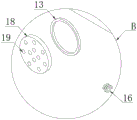
FIG. 4 is an enlarged view of the portion B of FIG. 2 according to the present invention;
fig. 5 is a schematic structural diagram of embodiment 2 provided by the present invention;
in the figure: the anti-collision device comprises a box body 1, a supporting plate 2, a blower body 3, a supporting block 4, a damping spring 5, a U-shaped block 6, a round rod 7, a base 8, a rod sleeve 9, a buffer spring 10, a supporting rod 11, a vent hole 12, silencing cotton 13, a sound-proof door 14, a sound-proof plate 15, a first anti-collision spring 16, a second anti-collision spring 17, a partition plate 18, a through groove 19 and a gauze 20.
Detailed Description
The preferred embodiments of the present invention will be described in conjunction with the accompanying drawings, and it will be understood that they are presented herein only to illustrate and explain the present invention, and not to limit the present invention.
Example 1:
referring to the attached drawings 1-4, the utility model provides a sound insulation device of a high-pressure blower, which comprises a box body 1, wherein a supporting plate 2 is arranged inside the box body 1, the top of the supporting plate 2 is fixedly connected with a blower body 3, and the bottom of the supporting plate 2 is provided with a movable damping component;
the movable damping component comprises a supporting block 4 and damping springs 5, the supporting block 4 is fixedly connected with the bottom of a supporting plate 2, the damping springs 5 are fixedly connected with the bottom of the supporting block 4, U-shaped blocks 6 are arranged at two ends of the supporting block 4, round rods 7 are fixedly connected to one sides of the two U-shaped blocks 6, the two round rods 7 respectively penetrate through two ends of the supporting block 4 and are rotatably connected with the supporting block 4, sliding grooves are formed in two side surfaces of the bottom of the box body 1, bases 8 are arranged in the two sliding grooves, the two bases 8 are respectively connected with the box body 1 in a sliding mode through the sliding grooves, rod sleeves 9 are fixedly connected to the tops of the two bases 8, damping springs 10 are arranged in the two rod sleeves 9, one ends of the two damping springs 10 are respectively fixedly connected with the bases 8, and supporting rods 11 are fixedly connected to the other ends of the two damping springs 10, the two support rods 11 are movably sleeved with the two rod sleeves 9 respectively, one ends of the two support rods 11, far away from the buffer spring 10, are fixedly connected with the bottoms of the U-shaped blocks 6 respectively, and vibration generated when the air blower body 3 operates can be effectively reduced by arranging movable damping components;
furthermore, both ends of the surface of one side of the box body 1 are respectively provided with a vent hole 12, silencing cotton 13 is fixedly connected in each vent hole 12, the vent holes 12 are matched with the input end of the blower body 3, the silencing cotton 13 is the prior art, and the arrangement of the silencing cotton 13 can greatly reduce the wind noise of the blower body 3 during operation;
furthermore, a sound insulation door 14 is arranged on one side of the box body 1, the sound insulation door 14 is connected with the box body 1 in a hinge mode, and the sound insulation door 14 can be arranged to facilitate installation, maintenance and disassembly of the blower body 3 inside the box body 1;
furthermore, a square groove is formed in the surface of one side of the box body 1, sound insulation boards 15 are arranged in the square groove, the sound insulation boards 15 are respectively and fixedly connected with the box body 1, the sound insulation boards 15 are in the prior art, and sound inside the box body 1 can be effectively isolated through the arrangement of the sound insulation boards 15;
furthermore, both sides of one end of the supporting plate 2 are fixedly connected with first anti-collision springs 16, both sides of the other end of the supporting plate 2 are fixedly connected with second anti-collision springs 17, and the supporting plate 2 can be prevented from shaking too much to damage the box body 1 when vibrating through the first anti-collision springs 16 and the second anti-collision springs 17;
further, be equipped with baffle 18 in the ventilation hole 12, a plurality of logical grooves 19 have been seted up to 18 side surfaces of baffle, it is a plurality of logical groove 19 is the circumference array distribution, through the setting of a plurality of logical grooves 19, can also completely cut off most dust when ventilative radiating.
The utility model discloses a use as follows: when the utility model is used, when the air blower body 3 runs, vibration is generated, the vibration force is transmitted to the supporting block 4 and the damping spring 5 through the supporting plate 2, the damping spring 5 is extruded to absorb most of the vibration force, simultaneously, the vibration force enables the two U-shaped blocks 6 to rotate in a small range by taking the round rod 7 as an axis, the two supporting rods 11 are pushed to be pressed downwards, the two supporting rods 11 respectively slide downwards in the two rod sleeves 9 and extrude the two buffer springs 10, the two buffer springs 10 absorb part of the vibration force and enable the two bases 8 to slide in the sliding chute, the vibration force is dispersed, absorbed and offset, the vibration force is greatly weakened and reduced, the vibration cannot influence the box body 1, simultaneously, the sound in the box body 1 is effectively isolated through the plurality of sound insulation plates 15 in the sound insulation box body 1, and the wind noise can be effectively reduced through the sound insulation cotton 13 in the ventilation holes 12, through the setting of a plurality of logical grooves 19, can also keep off most dust when ventilative heat dissipation.
Example 2:
referring to the attached drawing 5, the utility model provides a pair of high pressure air-blower's noise insulation, it is different with embodiment 1, be equipped with gauze 20 in the ventilation hole 12, gauze 20 and box 1 fixed connection through setting up gauze 20, can be to the inside effective ventilative heat dissipation of box 1 to can isolated partial dust, compare with embodiment 1, gauze 20's permeability is better.
The using process is as follows: when the utility model is used, when the blower body 3 is operated, vibration is generated, vibration force is transmitted to the supporting block 4 and the damping spring 5 through the supporting plate 2, the damping spring 5 is extruded to absorb most of the vibration force, simultaneously the vibration force enables the two U-shaped blocks 6 to rotate in a small range by taking the round rod 7 as an axis, the two supporting rods 11 are pushed to be pressed downwards, the two supporting rods 11 respectively slide downwards in the two rod sleeves 9 and extrude the two buffering springs 10, the two buffering springs 10 absorb part of the vibration force, the two bases 8 slide in the sliding grooves, the vibration force is dispersed and absorbed and offset, the vibration is greatly weakened and reduced, the vibration does not affect the box body 1, simultaneously, the sound in the box body 1 is effectively isolated through the plurality of sound insulation plates 15 in the box body 1, and simultaneously, the wind noise can be effectively reduced through the sound insulation cotton 13 in the ventilation holes 12, through setting up gauze 20, can be to the inside ventilative heat dissipation of box 1 effectively to can isolated some dust.
The above description is only a preferred embodiment of the present invention, and any person skilled in the art may modify the present invention or modify it into an equivalent technical solution by using the technical solutions described above. Therefore, any simple modifications or equivalent replacements made according to the technical solution of the present invention belong to the scope of the claimed invention as far as possible.
Claims (7)
1. The utility model provides a high pressure blower's noise insulation, includes box (1), its characterized in that: a supporting plate (2) is arranged in the box body (1), the top of the supporting plate (2) is fixedly connected with an air blower body (3), and a movable damping component is arranged at the bottom of the supporting plate (2);
the movable damping assembly comprises a supporting block (4) and damping springs (5), the supporting block (4) is fixedly connected with the bottom of the supporting plate (2), the damping springs (5) are fixedly connected with the bottom of the supporting block (4), U-shaped blocks (6) are arranged at two ends of the supporting block (4), round rods (7) are fixedly connected with one sides of the two U-shaped blocks (6), the two round rods (7) respectively penetrate through two ends of the supporting block (4) and are rotatably connected with the supporting block (4), sliding grooves are formed in two side surfaces of the bottom of the box body (1), bases (8) are arranged in the two sliding grooves, the two bases (8) are respectively connected with the box body (1) in a sliding mode through the sliding grooves, rod sleeves (9) are fixedly connected with the tops of the two bases (8), the damping springs (10) are arranged in the two rod sleeves (9), one ends of the two damping springs (10) are respectively fixedly connected with the bases (8), two equal fixedly connected with bracing piece (11) of buffer spring (10) other end, two bracing piece (11) cup joint with two pole cover (9) activities respectively, two buffer spring (10) one end is kept away from in bracing piece (11) respectively with U-shaped piece (6) bottom fixed connection.
2. The sound insulating device for a high pressure blower according to claim 1, wherein: ventilation holes (12) are formed in two ends of the surface of one side of the box body (1), and silencing cotton (13) is fixedly connected into the ventilation holes (12).
3. The sound insulating device for a high pressure blower according to claim 1, wherein: and a soundproof door (14) is arranged on one side of the box body (1), and the soundproof door (14) is connected with the box body (1) through a hinge.
4. The sound insulating device for a high pressure blower according to claim 1, wherein: a square groove is formed in the surface of one side of the box body (1), sound insulation boards (15) are arranged in the square groove, and the sound insulation boards (15) are fixedly connected with the box body (1) respectively.
5. The sound insulating device for a high pressure blower according to claim 1, wherein: the anti-collision device is characterized in that first anti-collision springs (16) are fixedly connected to two sides of one end of the supporting plate (2), and second anti-collision springs (17) are fixedly connected to two sides of the other end of the supporting plate (2).
6. The sound insulating device for a high pressure blower according to claim 2, wherein: a partition plate (18) is arranged in the ventilation hole (12), a plurality of through grooves (19) are formed in the surface of one side of the partition plate (18), and the through grooves (19) are distributed in a circumferential array mode.
7. The sound insulating device for a high pressure blower according to claim 2, wherein: a gauze (20) is arranged in the ventilation hole (12), and the gauze (20) is fixedly connected with the box body (1).
Priority Applications (1)
| Application Number | Priority Date | Filing Date | Title |
|---|---|---|---|
| CN202023248045.0U CN214036288U (en) | 2020-12-29 | 2020-12-29 | Sound insulation device of high-pressure air blower |
Applications Claiming Priority (1)
| Application Number | Priority Date | Filing Date | Title |
|---|---|---|---|
| CN202023248045.0U CN214036288U (en) | 2020-12-29 | 2020-12-29 | Sound insulation device of high-pressure air blower |
Publications (1)
| Publication Number | Publication Date |
|---|---|
| CN214036288U true CN214036288U (en) | 2021-08-24 |
Family
ID=77344266
Family Applications (1)
| Application Number | Title | Priority Date | Filing Date |
|---|---|---|---|
| CN202023248045.0U Active CN214036288U (en) | 2020-12-29 | 2020-12-29 | Sound insulation device of high-pressure air blower |
Country Status (1)
| Country | Link |
|---|---|
| CN (1) | CN214036288U (en) |
Cited By (1)
| Publication number | Priority date | Publication date | Assignee | Title |
|---|---|---|---|---|
| CN116447173A (en) * | 2023-05-18 | 2023-07-18 | 恒驰环保设备(南京)有限公司 | Multi-layer structure integrated type sound insulation device for blower and operation method thereof |
-
2020
- 2020-12-29 CN CN202023248045.0U patent/CN214036288U/en active Active
Cited By (2)
| Publication number | Priority date | Publication date | Assignee | Title |
|---|---|---|---|---|
| CN116447173A (en) * | 2023-05-18 | 2023-07-18 | 恒驰环保设备(南京)有限公司 | Multi-layer structure integrated type sound insulation device for blower and operation method thereof |
| CN116447173B (en) * | 2023-05-18 | 2023-10-31 | 恒驰环保设备(南京)有限公司 | Multi-layer structure integrated type sound insulation device for blower and operation method thereof |
Similar Documents
| Publication | Publication Date | Title |
|---|---|---|
| CN214036288U (en) | Sound insulation device of high-pressure air blower | |
| CN210271977U (en) | Heat-dissipation dustproof transformer | |
| CN210444464U (en) | Sound box damping support | |
| CN210491087U (en) | Router disconnection isolating device | |
| CN216905158U (en) | Network environment monitoring system | |
| CN209555514U (en) | A kind of sewing machine energy-saving electric machine radiator | |
| CN213342190U (en) | Wireless signal transmitting equipment for electronic communication | |
| CN208430653U (en) | A kind of hollow wall acoustic board | |
| CN215269237U (en) | Mute type radiator fan for 5G communication equipment | |
| CN206977619U (en) | A kind of computer communication complex base | |
| CN217389294U (en) | Diagnosis and message distribution device for automatic control system | |
| CN220273440U (en) | Noise reduction type motor | |
| CN218907106U (en) | Server support with bottom protection | |
| CN218041421U (en) | Communication gateway structure | |
| CN214482068U (en) | Computer network has safeguard function's control box | |
| CN216057288U (en) | High-performance transmission double-optical-fiber backup HDMI optical transceiver | |
| CN218152179U (en) | Damping mechanism of equipment in car | |
| CN208174898U (en) | A kind of computer network router | |
| CN215679018U (en) | Projector shell with reinforcing structure | |
| CN216150417U (en) | Oblique balance wheel angle-adjustable shunting mechanism of automatic sorting equipment | |
| CN219740802U (en) | Stable network communication transmission equipment | |
| CN219269218U (en) | Signal controller for broadcast television network transmission | |
| CN215188018U (en) | Internet of things router with good protection performance | |
| CN212696343U (en) | Installation base for communication | |
| CN219352105U (en) | Network signal transmitter encapsulation equipment |
Legal Events
| Date | Code | Title | Description |
|---|---|---|---|
| GR01 | Patent grant | ||
| GR01 | Patent grant |