CN214027001U - Adjustable helmet mechanism of moulding plastics - Google Patents
Adjustable helmet mechanism of moulding plastics Download PDFInfo
- Publication number
- CN214027001U CN214027001U CN202022530538.7U CN202022530538U CN214027001U CN 214027001 U CN214027001 U CN 214027001U CN 202022530538 U CN202022530538 U CN 202022530538U CN 214027001 U CN214027001 U CN 214027001U
- Authority
- CN
- China
- Prior art keywords
- adjusting
- injection molding
- movable block
- die
- forming
- Prior art date
- Legal status (The legal status is an assumption and is not a legal conclusion. Google has not performed a legal analysis and makes no representation as to the accuracy of the status listed.)
- Expired - Fee Related
Links
- 230000007246 mechanism Effects 0.000 title claims abstract description 21
- 238000000465 moulding Methods 0.000 title claims abstract description 17
- 239000004033 plastic Substances 0.000 title abstract description 10
- 229920003023 plastic Polymers 0.000 title abstract description 10
- 238000001746 injection moulding Methods 0.000 claims abstract description 39
- 239000000463 material Substances 0.000 claims description 7
- 230000002457 bidirectional effect Effects 0.000 claims 4
- 230000000694 effects Effects 0.000 description 4
- 238000002347 injection Methods 0.000 description 4
- 239000007924 injection Substances 0.000 description 4
- 238000007493 shaping process Methods 0.000 description 3
- 238000004519 manufacturing process Methods 0.000 description 2
- 239000000243 solution Substances 0.000 description 2
- 230000009286 beneficial effect Effects 0.000 description 1
- 238000004512 die casting Methods 0.000 description 1
- 238000006073 displacement reaction Methods 0.000 description 1
- 230000006872 improvement Effects 0.000 description 1
- 238000010137 moulding (plastic) Methods 0.000 description 1
- 229920001169 thermoplastic Polymers 0.000 description 1
- 229920001187 thermosetting polymer Polymers 0.000 description 1
- 230000009466 transformation Effects 0.000 description 1
Images
Landscapes
- Moulds For Moulding Plastics Or The Like (AREA)
Abstract
The utility model discloses an adjustable helmet mechanism of moulding plastics, include: the injection molding machine comprises an upper die unit and a lower die unit, wherein the upper die unit and the lower die unit are arranged on the injection molding machine and used for performing injection molding on a product through die assembly. In this way, the utility model relates to an adjustable helmet mechanism of moulding plastics not only can adjust the size of brim of a hat and bore, can improve product injection moulding's efficiency moreover, simple structure, facilitate the use.
Description
Technical Field
The utility model relates to an injection mold field especially relates to an adjustable helmet mechanism of moulding plastics.
Background
Injection molding is a method for producing and molding industrial products. The products are generally produced by rubber injection molding and plastic injection molding. The injection molding can be classified into injection molding and die casting.
An injection molding machine is a main molding apparatus for molding thermoplastic plastics or thermosetting materials into plastic products of various shapes by using a plastic molding die, and an injection mold is one of important structures of injection molding.
SUMMERY OF THE UTILITY MODEL
The utility model discloses the main technical problem who solves provides an adjustable helmet mechanism of moulding plastics, has advantages such as reliable performance height, location accuracy, compact structure, has extensive market prospect in injection mold's application and popularization simultaneously.
In order to solve the technical problem, the utility model discloses a technical scheme be:
there is provided an adjustable helmet injection molding mechanism comprising: the injection molding machine comprises an upper die unit, a rotary material tray and a lower die unit, wherein the upper die unit is arranged on the injection molding machine, the rotary material tray is arranged below the upper die unit, 2 or more than 2 lower die units are movably arranged on the rotary material tray,
the upper die unit comprises an upper die base, a forming convex die, guide columns, positioning rods, limiting blocks, a movable groove, an ejector plate and a stripping ejector pin, the forming convex die is arranged in the middle of the top surface of the upper die base, the guide columns are arranged on the periphery of the bottom surface of the upper die base, the positioning rods are arranged on the periphery of the forming convex die, the limiting blocks are arranged on the bottom surface of the upper die base,
the movable groove is arranged in the upper die base, the ejector pin plate is movably arranged in the movable groove, the demolding driving device drives the ejector pin plate to move up and down in the movable groove, the top of the ejector pin is arranged on the ejector pin plate, the lower end of the ejector pin penetrates through the upper die base and moves up and down in a demolding hole in the molding male die,
the lower die unit comprises a lower die base, a forming female die, a guide groove, a positioning hole and an adjusting unit,
the forming female die is arranged in the middle of the top surface of the lower die holder, the guide grooves are arranged around the top surface of the lower die holder, the positioning holes are arranged around the forming female die, the guide grooves are movably connected with the guide posts, the positioning rods are movably connected with the positioning holes, the forming male die is movably connected with the forming female die,
when the upper die holder and the lower die holder are assembled, the top surface of the lower die holder is contacted with the bottom surface of the limiting block, at the moment, an adjusting space is arranged between the lower die holder and the upper die holder, the front surface and the back surface of the adjusting space are sealed by a forming male die and a forming female die, adjusting gaps are arranged on two sides of the adjusting space, the adjusting unit is movably arranged in the adjusting gaps,
the adjusting unit comprises an adjusting driving device, a guide slide bar, a first adjusting movable block, a second adjusting movable block, a first forming groove and a second forming groove, the adjusting driving device and the guide slide bar are respectively arranged on two side walls of the lower die holder, the first adjusting movable block and the second adjusting movable block are relatively arranged in the adjusting gap, the inner side of the first adjusting block is provided with the first forming groove, the inner side of the second adjusting block is provided with the second forming block, the first forming groove and the second forming groove are matched to form the bottom of the helmet and the helmet brim structure, and the adjusting driving device drives the first adjusting movable block and the second adjusting movable block to move relatively.
In a preferred embodiment of the present invention, the adjusting driving device includes a two-way screw, a nut, a screw seat, and a motor, the screw seat is disposed on the sidewall of the lower die seat, the two ends of the two-way screw are movably connected to the screw seat, the motor drives the two-way screw to rotate, two, the nut is movably disposed on two thread segments of the two-way screw, and the nut is fixedly connected to the first adjusting movable block and the second adjusting movable block.
In a preferred embodiment of the present invention, one end of the first adjusting movable block is connected to the adjusting driving device, and the other end of the first adjusting movable block is movably connected to the guide sliding rod.
In a preferred embodiment of the present invention, one end of the second adjusting movable block is connected to the adjusting driving device, and the other end of the second adjusting movable block is movably connected to the guide sliding rod.
In a preferred embodiment of the present invention, the rotating tray is connected to an index plate.
In a preferred embodiment of the present invention, when the lower mold unit moves to a position directly below the upper mold unit, the upper mold unit and the lower mold unit are closed to perform injection molding of the product.
In a preferred embodiment of the present invention, the limiting blocks are disposed on four corners, two opposite sides or four sides of the bottom surface of the upper die base.
In a preferred embodiment of the present invention, the bottom surface of the upper die base is closely attached to the top surface of the adjusting movable block, and the top surface of the lower die base is closely attached to the bottom surface of the adjusting movable block during die assembly.
In a preferred embodiment of the present invention, the first adjusting movable block and the second adjusting movable block are respectively connected with one adjusting driving device.
In a preferred embodiment of the present invention, an injection runner is disposed in the forming male die.
The utility model has the advantages that: not only can adjust the size of brim of a hat and bore, can improve product injection moulding's efficiency moreover, simple structure, facilitate the use.
Drawings
In order to more clearly illustrate the technical solutions of the embodiments of the present invention, the drawings used in the description of the embodiments are briefly introduced below, and it is obvious that the drawings in the following description are only some embodiments of the present invention, and for those skilled in the art, other drawings can be obtained without inventive work, wherein:
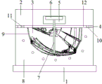
fig. 1 is a schematic cross-sectional view of a preferred embodiment of an injection molding mechanism of an adjustable helmet according to the present invention;
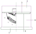
fig. 2 is a schematic front view of a preferred embodiment of an injection molding mechanism for an adjustable helmet according to the present invention.
Detailed Description
The technical solutions in the embodiments of the present invention will be described clearly and completely below, and it should be apparent that the described embodiments are only some embodiments of the present invention, but not all embodiments. Based on the embodiments in the present invention, all other embodiments obtained by a person skilled in the art without creative efforts belong to the protection scope of the present invention.
Referring to fig. 1-2, an embodiment of the present invention includes:
an adjustable helmet injection molding mechanism, the structure of which comprises: the mould comprises an upper mould unit, a rotary tray 1 and a lower mould unit.
Go up the mould unit and set up on the injection molding machine, rotatory charging tray set up in go up the below of mould unit, 2 or more than 2 lower mould unit activity set up in on the rotatory charging tray, when a lower mould unit is closing the mould and moulding plastics, the product on the lower mould unit in addition can carry out other processing or go up unloading, can effectual improvement production's efficiency like this, be connected with graduated disk or other drive device on the rotatory charging tray for rotatory charging tray drives lower mould unit moves, when lower mould unit moves and goes up the mould unit under, go up the mould unit with lower mould unit closing mould carries out product injection moulding.
The upper die unit comprises an upper die base 2, a forming male die 3, a guide column, a positioning rod, a limiting block 4, a movable groove 5, an ejector pin plate 6 and a stripping ejector pin 7.
The forming male die is arranged in the middle of the top surface of the upper die base, the guide columns are arranged on the periphery of the bottom surface of the upper die base, the positioning rods are arranged on the periphery of the forming male die, and the limiting blocks are arranged on four corners, two opposite sides or four opposite sides of the bottom surface of the upper die base.
The movable groove set up in the upper die base, the thimble board activity set up in the movable groove, drawing of patterns drive arrangement drives the thimble board is in the upper and lower motion in the movable groove, the top of thimble set up in on the thimble board, its lower extreme passes the upper die base to upper and lower motion in the drawing of patterns hole on the shaping terrace die.
When the upper die unit and the lower die unit are assembled, the ejector pin plate is driven by the demolding driving device to move upwards, and the ejector pins retract into the demolding holes, so that the streamline on the surface of the jig core is kept consistent, and the product is convenient to perform injection molding. When the upper die unit and the lower die unit are opened, the ejector driving device drives the ejector plate to move downwards, the ejector pin moves towards the outside of the demolding hole, so that the tail end of the ejector pin protrudes out of the outer surface of the forming male die, and the ejector pin can peel off a product from the jig core at the moment, so that the demolding effect is realized.
The lower die unit comprises a lower die base 8, a forming female die 9, a guide groove, a positioning hole and an adjusting unit.
The forming female die is arranged in the middle of the top surface of the lower die holder, the guide grooves are formed in the periphery of the top surface of the lower die holder, and the positioning holes are formed in the periphery of the forming female die. The guide way with the guide post is connected, the locating lever with locating hole swing joint, the shaping terrace die with the shaping die is connected.
When the upper die base and the lower die base are assembled, the top surface of the lower die base is contacted with the bottom surface of the limiting block, at the moment, an adjusting space 12 is arranged between the lower die base and the upper die base, namely, the bottom surface of the upper die base is not directly contacted with the top surface of the lower die base, but a molding cavity with a closed periphery needs to be formed for accurate injection molding, so that the front surface and the back surface of the adjusting space are directly closed by clinging the molding male die to the side wall of the molding female die, adjusting gaps are arranged on two sides of the adjusting space, and the adjusting units are movably arranged in the adjusting gaps so as to close the left side and the right side of the adjusting space and adjust the left-right distance of the adjusting space.
The adjusting unit comprises an adjusting driving device, a guide slide bar, a first adjusting movable block 10, a second adjusting movable block 11, a first forming groove and a second forming groove, the adjusting driving device and the guide slide bar are respectively arranged on two side walls of the lower die holder, the first adjusting movable block and the second adjusting movable block are oppositely arranged in the adjusting gap, the first forming groove is arranged on the inner side of the first adjusting block, the second forming block is arranged on the inner side of the second adjusting block, the first forming groove and the second forming groove are used for forming the lowest end and the brim of a helmet, wherein one end of the first adjusting movable block and one end of the second adjusting movable block are both connected with the adjusting driving device, the other ends of the first adjusting movable block and the second adjusting movable block are both movably connected with the guide slide bar, and the adjusting driving device drives the first adjusting movable block and the second adjusting movable block to move relatively, to enlarge or reduce the caliber of the helmet and the length of the visor.
When the die is used, the positions of the first adjusting movable block and the second adjusting movable block are adjusted according to use requirements, then the die is closed, and when the die is closed, the bottom surface of the upper die base and the top surface of the lower die base are respectively attached to the adjusting movable blocks, so that the displacement of the upper die base and the adjusting movable blocks in the injection molding process is prevented.
Adjust drive arrangement and include two-way screw rod, nut, screw rod seat, motor, the screw rod seat set up in on the lateral wall of die holder, two-way screw rod both ends with screw rod seat swing joint, the motor drives two-way screw rod is rotatory, two the nut activity set up in on two screw thread sections of two-way screw rod, the nut with first regulation movable block and second regulation movable block fixed connection can improve like this the first accurate nature that adjusts movable block and second regulation movable block and remove improves work efficiency.
The utility model relates to an adjustable helmet mechanism of moulding plastics's beneficial effect is: not only can adjust the size of brim of a hat and bore, can improve product injection moulding's efficiency moreover, simple structure, facilitate the use.
The above only is the embodiment of the present invention, not limiting the patent scope of the present invention, all of which utilize the equivalent structure or equivalent flow transformation made by the content of the specification of the present invention, or directly or indirectly applied to other related technical fields, all included in the same way in the patent protection scope of the present invention.
Claims (10)
1. An adjustable helmet injection molding mechanism, comprising: the injection molding machine comprises an upper die unit, a rotary material tray and a lower die unit, wherein the upper die unit is arranged on the injection molding machine, the rotary material tray is arranged below the upper die unit, 2 or more than 2 lower die units are movably arranged on the rotary material tray,
the upper die unit comprises an upper die base, a forming convex die, guide columns, positioning rods, limiting blocks, a movable groove, an ejector plate and a stripping ejector pin, the forming convex die is arranged in the middle of the top surface of the upper die base, the guide columns are arranged on the periphery of the bottom surface of the upper die base, the positioning rods are arranged on the periphery of the forming convex die, the limiting blocks are arranged on the bottom surface of the upper die base,
the movable groove is arranged in the upper die base, the ejector pin plate is movably arranged in the movable groove, the demolding driving device drives the ejector pin plate to move up and down in the movable groove, the top of the ejector pin is arranged on the ejector pin plate, the lower end of the ejector pin penetrates through the upper die base and moves up and down in a demolding hole in the molding male die,
the lower die unit comprises a lower die base, a forming female die, a guide groove, a positioning hole and an adjusting unit,
the forming female die is arranged in the middle of the top surface of the lower die holder, the guide grooves are arranged around the top surface of the lower die holder, the positioning holes are arranged around the forming female die, the guide grooves are movably connected with the guide posts, the positioning rods are movably connected with the positioning holes, the forming male die is movably connected with the forming female die,
when the upper die holder and the lower die holder are assembled, the top surface of the lower die holder is contacted with the bottom surface of the limiting block, at the moment, an adjusting space is arranged between the lower die holder and the upper die holder, the front surface and the back surface of the adjusting space are sealed by a forming male die and a forming female die, adjusting gaps are arranged on two sides of the adjusting space, the adjusting unit is movably arranged in the adjusting gaps,
the adjusting unit comprises an adjusting driving device, a guide slide bar, a first adjusting movable block, a second adjusting movable block, a first forming groove and a second forming groove, the adjusting driving device and the guide slide bar are respectively arranged on two side walls of the lower die holder, the first adjusting movable block and the second adjusting movable block are relatively arranged in the adjusting gap, the inner side of the first adjusting movable block is provided with the first forming groove, the inner side of the second adjusting movable block is provided with the second forming block, the first forming groove and the second forming groove are matched to form the bottom of the helmet and a helmet brim structure, and the adjusting driving device drives the first adjusting movable block and the second adjusting movable block to move relatively.
2. The adjustable helmet injection molding mechanism according to claim 1, wherein the adjustment driving device comprises a bidirectional screw, a nut, a screw seat, and a motor, the screw seat is disposed on the sidewall of the lower die seat, two ends of the bidirectional screw are movably connected with the screw seat, the motor drives the bidirectional screw to rotate, the two nuts are movably disposed on two thread segments of the bidirectional screw, and the nut is fixedly connected with the first adjustment movable block and the second adjustment movable block.
3. The injection molding mechanism of claim 1, wherein one end of the first adjustable block is connected to the adjustment driving device, and the other end of the first adjustable block is movably connected to the guiding sliding rod.
4. The adjustable helmet injection molding mechanism of claim 1, wherein one end of the second adjustable moving block is connected to the adjustment driving device, and the other end of the second adjustable moving block is movably connected to the guiding sliding rod.
5. The adjustable helmet injection molding mechanism of claim 1, wherein an indexing plate is connected to the rotating tray.
6. The adjustable helmet injection molding mechanism of claim 1, wherein the upper mold unit and the lower mold unit are closed for product injection molding when the lower mold unit moves to a position directly below the upper mold unit.
7. The adjustable injection molding mechanism for a helmet as claimed in claim 1, wherein the stoppers are disposed at four corners, two opposite sides, or four sides of the bottom surface of the upper mold base.
8. The adjustable helmet injection molding mechanism of claim 1, wherein the bottom surface of the upper mold base is in close contact with the top surface of the adjusting movable block, and the top surface of the lower mold base is in close contact with the bottom surface of the adjusting movable block during mold closing.
9. The adjustable helmet injection molding mechanism of claim 1, wherein the first adjustable movable block and the second adjustable movable block are each connected to one of the adjustment driving devices.
10. The adjustable helmet injection molding mechanism of claim 1, wherein an injection molding runner is disposed in the molding male mold.
Priority Applications (1)
| Application Number | Priority Date | Filing Date | Title |
|---|---|---|---|
| CN202022530538.7U CN214027001U (en) | 2020-11-05 | 2020-11-05 | Adjustable helmet mechanism of moulding plastics |
Applications Claiming Priority (1)
| Application Number | Priority Date | Filing Date | Title |
|---|---|---|---|
| CN202022530538.7U CN214027001U (en) | 2020-11-05 | 2020-11-05 | Adjustable helmet mechanism of moulding plastics |
Publications (1)
| Publication Number | Publication Date |
|---|---|
| CN214027001U true CN214027001U (en) | 2021-08-24 |
Family
ID=77356787
Family Applications (1)
| Application Number | Title | Priority Date | Filing Date |
|---|---|---|---|
| CN202022530538.7U Expired - Fee Related CN214027001U (en) | 2020-11-05 | 2020-11-05 | Adjustable helmet mechanism of moulding plastics |
Country Status (1)
| Country | Link |
|---|---|
| CN (1) | CN214027001U (en) |
-
2020
- 2020-11-05 CN CN202022530538.7U patent/CN214027001U/en not_active Expired - Fee Related
Similar Documents
| Publication | Publication Date | Title |
|---|---|---|
| CN211591158U (en) | Internal core-pulling injection mold with adjustable core-pulling distance | |
| CN217454717U (en) | Novel plastic toy injection mold | |
| CN105034279A (en) | Double-color switch knob injection mold | |
| CN208148388U (en) | A kind of internal screw thread rotation depanning mold | |
| CN213227388U (en) | Injection molding and demolding structure of plastic part | |
| CN212888679U (en) | Double-guide mechanism of injection mold frame | |
| CN212498754U (en) | High efficiency junction box lid injection mold | |
| CN214027001U (en) | Adjustable helmet mechanism of moulding plastics | |
| CN217169500U (en) | Plastic building block injection molding precision mold with lateral parting core pulling function | |
| CN213440951U (en) | Plastic chassis injection mold | |
| CN214820548U (en) | Plastic product injection mold | |
| CN212097368U (en) | Curved surface piece injection mold capable of achieving rapid demolding | |
| CN103507219A (en) | Mold for injection molding of parts with internal threads | |
| CN210308893U (en) | Injection mold easy to demold | |
| CN214000430U (en) | Injection mold structure | |
| CN219235999U (en) | Injection molding core-pulling structure and injection mold | |
| CN218462812U (en) | Plastic injection mold easy to demould | |
| CN214026902U (en) | Horizontal helmet injection mold | |
| CN110027167A (en) | A kind of appliance switch injection mold | |
| CN220864643U (en) | Multicavity injection molding device | |
| CN215472848U (en) | High-precision injection mold with bidirectional spiral demolding structure | |
| CN219727062U (en) | Oblique demolding mechanism of rear cover mold of electric locomotive tube | |
| CN218803664U (en) | Injection molding machine is used in casing subassembly injection molding production | |
| CN220681511U (en) | Detector shell injection mold with guide mechanism | |
| CN204505705U (en) | A kind of injection mold for making internal thread knob |
Legal Events
| Date | Code | Title | Description |
|---|---|---|---|
| GR01 | Patent grant | ||
| GR01 | Patent grant | ||
| CF01 | Termination of patent right due to non-payment of annual fee |
Granted publication date: 20210824 |
|
| CF01 | Termination of patent right due to non-payment of annual fee |