CN214021008U - Milling equipment - Google Patents
Milling equipment Download PDFInfo
- Publication number
- CN214021008U CN214021008U CN202022993252.2U CN202022993252U CN214021008U CN 214021008 U CN214021008 U CN 214021008U CN 202022993252 U CN202022993252 U CN 202022993252U CN 214021008 U CN214021008 U CN 214021008U
- Authority
- CN
- China
- Prior art keywords
- box
- milling
- fixed mounting
- powder
- grinding
- Prior art date
- Legal status (The legal status is an assumption and is not a legal conclusion. Google has not performed a legal analysis and makes no representation as to the accuracy of the status listed.)
- Active
Links
Images
Landscapes
- Crushing And Grinding (AREA)
Abstract
The utility model discloses a milling equipment relates to graphite electrode technical field. This milling equipment, including the crocus case, one side fixed mounting of crocus case has the biax motor, the equal fixed mounting of both sides inner wall of crocus case has the connecting plate and connects the diaphragm, the adjacent lateral wall fixed mounting of two sets of connecting plates has the grinding box, the inboard top of crocus case is rotated and is installed the hydraulic stem, the free end fixed mounting of hydraulic stem has the diaphragm, the bottom fixed mounting of diaphragm has the grinding head, the adjacent lateral wall fixed mounting of two sets of connection diaphragms has the milling chamber, one side inner wall of crocus case is rotated and is installed the dwang. This milling equipment, through grinding head preliminary grinding and smashing once more of helical blade, the suction pump is retrieved the graphite electrode powder that does not reach the standard, so can grind once more the powder and smash until unqualified graphite electrode powder reaches the standard, smashes through the grinding of so many times, has guaranteed the off-the-shelf quality of graphite powder electrode.
Description
Technical Field
The utility model relates to a graphite electrode technical field specifically is a milling equipment.
Background
The graphite electrode is made up by using petroleum coke and needle coke as raw material and coal pitch as binding agent through the processes of calcining, proportioning, kneading, pressing, roasting, graphitizing and machining, and is a conductor which can release electric energy in the form of electric arc in electric arc furnace to heat and melt furnace charge. Graphite electrode mainly includes four types of ordinary power graphite electrode, anti-oxidation coating graphite electrode, high power graphite electrode and super high power graphite electrode, and graphite electrode needs carry out the crocus to it in the course of working and handles, and general graphite electrode material is when carrying out the crocus, and machining efficiency hangs down can appear, and the graphite electrode powder that grinds out is fine and smooth not enough needs carry out secondary operation, waste time.
SUMMERY OF THE UTILITY MODEL
An object of the utility model is to provide a milling equipment to solve at least one problem that proposes in the above-mentioned background art.
In order to achieve the above object, the utility model provides a following technical scheme: a milling device comprises a milling box, wherein a double-shaft motor is fixedly mounted on one side of the milling box, connecting plates and connecting transverse plates are fixedly mounted on the inner walls of the two sides of the milling box, a milling box is fixedly mounted on the adjacent side walls of the two groups of connecting plates, a hydraulic rod is rotatably mounted at the top of the inner side of the milling box, a transverse plate is fixedly mounted at the free end of the hydraulic rod, a grinding head is fixedly mounted at the bottom of the transverse plate, a milling chamber is fixedly mounted on the adjacent side walls of the two groups of connecting transverse plates, a rotating rod is rotatably mounted on the inner wall of one side of the milling box, one end of the rotating rod extends into the milling chamber and is fixedly connected with a spiral blade, the other end of the rotating rod is fixedly connected with an output shaft of the double-shaft motor through a coupler, an opening is formed in the bottom of the milling chamber, a first filter screen is fixedly mounted in the opening, a discharging pipe is fixedly connected with the bottom of the milling box, one end of the discharging pipe extends into the milling box, one side outer wall fixedly connected with inlet pipe of crocus case, the one end of inlet pipe is passed the crocus case and is extended to in the grinding box, it is equipped with first bevel gear to overlap through the shaft coupling on the other end output shaft of biax motor, the top of crocus case is rotated and is installed the connecting rod, connecting rod and hydraulic stem fixed mounting, the top cover of connecting rod is equipped with the second belt pulley, one side outer wall fixed mounting of crocus case has the backup pad, it installs the rotation montant to rotate in the backup pad, the bottom cover that rotates the montant is equipped with second bevel gear, first bevel gear meshes with second bevel gear mutually, the top cover that rotates the montant is equipped with first belt pulley, all the cover is equipped with the belt on first belt pulley and the second belt pulley.
Preferably, the top fixed mounting of milling chamber has two sets of swash plates, and two sets of swash plates are arranged relatively, and the swash plate all with connecting plate fixed connection.
Preferably, the box is collected to the graphite powder has been placed to the bottom of crocus case, and the both sides inner wall fixed mounting that the box was collected to the graphite powder has two sets of boards of placing, places and has placed the second filter screen on the board.
Preferably, the rotating rod is sleeved with a cam.
Preferably, the top fixed mounting who connects the diaphragm has the suction pump, and the input fixedly connected with of suction pump inhales the powder pipe, inhales the powder pipe and is located the top of second filter screen and contactless, and the output fixedly connected with of suction pump goes out the powder pipe, and the one end that goes out the powder pipe passes the connecting plate and communicates with each other with the inlet pipe.
Preferably, the spout has been seted up to the inner wall of crocus case, and slidable mounting has the slider in the spout, and one side fixed connection of box is collected with the graphite powder to the slider to make crocus case and graphite powder collect box slidable mounting.
Compared with the prior art, the beneficial effects of the utility model are that:
(1) this milling equipment, through the grinding head, grind the box, the hydraulic stem, the connecting rod, first belt pulley, the second belt pulley, the belt, rotate the montant, the dwang, double-shaft motor, first bevel gear, second bevel gear, the helical blade, inhale the powder pipe, go out the powder pipe, the discharging pipe, the cooperation of inlet pipe is used, make graphite electrode get into the device after, smash once more through the preliminary grinding of grinding head and helical blade, it retrieves to the graphite electrode powder that does not reach the standard to inhale the pump, the powder of retrieving can grind once more and smash until unqualified graphite electrode powder reaches the standard, smash through the grinding of so many times, the off-the-shelf quality of graphite powder electrode has been guaranteed.
(2) This milling equipment uses through the cooperation of first filter screen, second filter screen, double-shaft motor, cam, can carry out a lot of to the graphite electrode powder after grinding smashes and filter, drives the cam through double-shaft motor and rotates the filterable efficiency of messenger graphite electrode powder and become fast, has saved the time.
Drawings
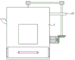
Fig. 1 is a front view of the present invention;
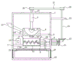
fig. 2 is a cross-sectional view of the present invention;
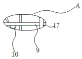
fig. 3 is an enlarged view of the part a of the present invention.
In the figure: 1 milling case, 2 biax motors, 3 connecting plates, 4 grinding boxes, 5 hydraulic stems, 6 grinding heads, 7 connection diaphragm, 8 milling chambers, 9 dwang, 10 spiral blade, 11 first filter screens, 12 discharging pipes, 13 suction pumps, 14 powder suction pipes, 15 inlet pipes, 16 powder outlet pipes, 17 cams, 18 graphite powder collection boxes, 19 placing plates, 20 second filter screens, 21 first bevel gears, 22 second bevel gears, 23 supporting plates, 24 rotation montants, 25 connecting rods, 26 second belt pulleys, 27 belts, 28 swash plates, 29 first belt pulleys.
Detailed Description
The technical solutions in the embodiments of the present invention will be described clearly and completely with reference to the accompanying drawings in the embodiments of the present invention, and it is obvious that the described embodiments are only some embodiments of the present invention, not all embodiments. Based on the embodiments in the present invention, all other embodiments obtained by a person skilled in the art without creative work belong to the protection scope of the present invention.
Referring to fig. 1-3, the present invention provides a technical solution:
the utility model provides a milling equipment, includes crocus case 1, and one side fixed mounting of crocus case 1 has biax motor 2, and the equal fixed mounting of both sides inner wall of crocus case 1 has connecting plate 3 and connection diaphragm 7, and the adjacent lateral wall fixed mounting of two sets of connecting plates 3 has grinding box 4. The inboard top of crocus case 1 rotates installs hydraulic stem 5, and the free end fixed mounting of hydraulic stem 5 has the diaphragm, and the bottom fixed mounting of diaphragm has grinding head 6. And the adjacent side walls of the two groups of connecting transverse plates 7 are fixedly provided with grinding chambers 8. Two groups of inclined plates 28 are fixedly installed at the top of the grinding chamber 8, the two groups of inclined plates 28 are oppositely arranged, and the inclined plates 28 are fixedly connected with the connecting plate 3. One side inner wall of crocus box 1 rotates installs dwang 9, and the one end of dwang 9 extends to the inside and the fixedly connected with helical blade 10 of milling chamber 8, and the other end of dwang 9 passes through shaft coupling fixed connection with the one end output shaft of double-shaft motor 2.
The opening has been seted up to the bottom of milling chamber 8, fixed mounting has first filter screen 11 in the opening, grind the bottom fixedly connected with discharging pipe 12 of box 4, the one end of discharging pipe 12 extends to in grinding box 4, the top fixed mounting who connects diaphragm 7 has suction pump 13, suction pump 13's input fixedly connected with inhales powder pipe 14, it is located second filter screen 20's top and contactless to inhale powder pipe 14, suction pump 13's output fixedly connected with goes out powder pipe 16, the one end that goes out powder pipe 16 passes connecting plate 3 and communicates with each other with inlet pipe 15, one side outer wall fixedly connected with inlet pipe 15 of crocus box 1, the one end of inlet pipe 15 is passed crocus box 1 and is extended to grinding box 4 in, graphite powder collection box 18 has been placed to the bottom of crocus box 1. The spout has been seted up to the inner wall of crocus box 1, and slidable mounting has the slider in the spout, and one side fixed connection of box 18 is collected with the graphite powder to the slider to make crocus box 1 and 18 slidable mounting of box are collected to the graphite powder.
Graphite powder collects box 18's both sides inner wall fixed mounting has two sets of boards 19 of placing, places and has placed second filter screen 20 on the board 19, and the cover is equipped with cam 17 on the dwang 9, and second filter screen 20 can be relieved when cam 17 follows the dwang 9 rotation to pat second filter screen 20, so can smash the graphite electrode powder after the filtration many times to the grinding.
The glass window is installed on the milling box 1, an opening is formed in the front side of the milling box 1, and a handle is fixedly installed on the front side of the graphite powder collecting box 18.
The other end output shaft of the double-shaft motor 2 is sleeved with a first bevel gear 21 through a coupler, the top of the grinding box 1 is rotatably provided with a connecting rod 25, the connecting rod 25 is fixedly installed with the hydraulic rod 5, and the top of the connecting rod 25 is sleeved with a second belt pulley 26. A supporting plate 23 is fixedly installed on the outer wall of one side of the grinding box 1, a rotating vertical rod 24 is installed on the supporting plate 23 in a rotating mode, a second bevel gear 22 is sleeved at the bottom of the rotating vertical rod 24, and the first bevel gear 21 is meshed with the second bevel gear 22. The top cover of rotating montant 24 is equipped with first belt pulley 29, all is equipped with belt 27 on first belt pulley 29 and the second belt pulley 26 to make second belt pulley 26 pass through belt 27 and be connected with first belt pulley 29 transmission.
The working principle is as follows: putting a graphite electrode to be milled into a grinding box 4 through a feeding pipe 15, controlling the free end of a hydraulic rod 5 to move downwards, driving a transverse plate to move downwards, driving a grinding head 6 to move downwards, controlling one end of a double-shaft motor 2 to start, driving a first bevel gear 21 to rotate by the forward rotation of the double-shaft motor 2, driving a second bevel gear 22 to rotate, driving a rotating vertical rod 24 to rotate, driving a first belt pulley 29 to rotate, driving a second belt pulley 26 to transmit through a belt 27 by the first belt pulley 29, driving a connecting rod 25 to rotate by the second belt pulley 26, driving the hydraulic rod 5 to rotate, driving the transverse plate to rotate, driving the grinding head 6 to rotate, and primarily grinding the graphite electrode; graphite electrode after preliminary grinding enters into milling chamber 8 through discharging pipe 12, other end output shaft through control double-shaft motor 2 drives dwang 9 and rotates, drive helical blade 10 and carry out the secondary crocus to graphite electrode, graphite electrode after passing through the secondary crocus falls on second filter screen 20 through first filter screen 11, drive cam 17 through dwang 9 and pat second filter screen 20, start suction pump 13, retrieve the graphite electrode powder that does not pass through second filter screen 20 through inhaling powder pipe 14, go into milling box 4 through powder outlet pipe 16 and carry out the crocus once more, go into many times crocus, until graphite electrode powder passes through second filter screen 20 and accomplish the crocus operation, graphite powder through the secondary crocus enters into graphite powder collection box 18, control double-shaft motor 2's stopping, control hydraulic stem 5 moves upwards, drive diaphragm upward movement, the grinding head 6 is driven to move upwards, the graphite powder collecting box 18 is drawn out, and the ground graphite powder is treated.
Although embodiments of the present invention have been shown and described, it will be appreciated by those skilled in the art that changes, modifications, substitutions and alterations can be made in these embodiments without departing from the principles and spirit of the invention, the scope of which is defined in the appended claims and their equivalents.
Claims (6)
1. The utility model provides a milling equipment, includes milling box (1), its characterized in that: one side of the milling box (1) is fixedly provided with a double-shaft motor (2), the inner walls of the two sides of the milling box (1) are fixedly provided with a connecting plate (3) and a connecting transverse plate (7), the adjacent side walls of the two groups of connecting plates (3) are fixedly provided with a milling box (4), the top of the inner side of the milling box (1) is rotatably provided with a hydraulic rod (5), the free end of the hydraulic rod (5) is fixedly provided with a transverse plate, the bottom of the transverse plate is fixedly provided with a grinding head (6), the adjacent side walls of the two groups of connecting transverse plates (7) are fixedly provided with a milling chamber (8), the inner wall of one side of the milling box (1) is rotatably provided with a rotating rod (9), one end of the rotating rod (9) extends to the inside of the milling chamber (8) and is fixedly connected with a spiral blade (10, the bottom of milling chamber (8) has been seted up the opening, fixed mounting has first filter screen (11) in the opening, the bottom fixedly connected with discharging pipe (12) of grinding box (4), the one end of discharging pipe (12) extends to in grinding box (4), one side outer wall fixedly connected with inlet pipe (15) of milling box (1), the one end of inlet pipe (15) is passed milling box (1) and is extended to in grinding box (4), it overlaps first bevel gear (21) to overlap through the shaft coupling on the other end output shaft of biax motor (2), connecting rod (25) is installed in the top rotation of milling box (1), connecting rod (25) and hydraulic stem (5) fixed mounting, the top cover of connecting rod (25) is equipped with second belt pulley (26), one side outer wall fixed mounting of milling box (1) has backup pad (23), it installs rotation montant (24) to rotate on backup pad (23), the bottom of the rotating vertical rod (24) is sleeved with a second bevel gear (22), the first bevel gear (21) is meshed with the second bevel gear (22), the top of the rotating vertical rod (24) is sleeved with a first belt pulley (29), and the first belt pulley (29) and the second belt pulley (26) are both sleeved with a belt (27).
2. A milling apparatus as claimed in claim 1, characterized in that: the top fixed mounting of milling chamber (8) has two sets of swash plates (28), and two sets of swash plates (28) are arranged relatively, and swash plate (28) all with connecting plate (3) fixed connection.
3. A milling apparatus as claimed in claim 1, characterized in that: graphite powder collecting box (18) have been placed to the bottom of crocus case (1), and the both sides inner wall fixed mounting of graphite powder collecting box (18) has two sets of boards (19) of placing, places second filter screen (20) on board (19).
4. A mill according to claim 3 wherein: the rotating rod (9) is sleeved with a cam (17).
5. A mill according to claim 4, characterized in that: the top fixed mounting who connects diaphragm (7) has suction pump (13), and the input fixedly connected with of suction pump (13) inhales powder pipe (14), inhales powder pipe (14) and is located the top of second filter screen (20) and contactless, and the output fixedly connected with of suction pump (13) goes out powder pipe (16), and the one end that goes out powder pipe (16) passes connecting plate (3) and communicates with each other with inlet pipe (15).
6. A mill according to claim 5, characterized in that: the spout has been seted up to the inner wall of crocus case (1), and slidable mounting has the slider in the spout, and one side fixed connection of box (18) is collected with graphite powder to the slider to make crocus case (1) collect box (18) slidable mounting with graphite powder.
Priority Applications (1)
| Application Number | Priority Date | Filing Date | Title |
|---|---|---|---|
| CN202022993252.2U CN214021008U (en) | 2020-12-14 | 2020-12-14 | Milling equipment |
Applications Claiming Priority (1)
| Application Number | Priority Date | Filing Date | Title |
|---|---|---|---|
| CN202022993252.2U CN214021008U (en) | 2020-12-14 | 2020-12-14 | Milling equipment |
Publications (1)
| Publication Number | Publication Date |
|---|---|
| CN214021008U true CN214021008U (en) | 2021-08-24 |
Family
ID=77336592
Family Applications (1)
| Application Number | Title | Priority Date | Filing Date |
|---|---|---|---|
| CN202022993252.2U Active CN214021008U (en) | 2020-12-14 | 2020-12-14 | Milling equipment |
Country Status (1)
| Country | Link |
|---|---|
| CN (1) | CN214021008U (en) |
-
2020
- 2020-12-14 CN CN202022993252.2U patent/CN214021008U/en active Active
Similar Documents
| Publication | Publication Date | Title |
|---|---|---|
| CN211755855U (en) | Grinding machine for pharmaceutical preparations | |
| CN209613092U (en) | A kind of dust collection processing unit producing ultra high power graphite electrode | |
| CN214021008U (en) | Milling equipment | |
| CN213528996U (en) | Brown sugar reducing mechanism | |
| CN209791656U (en) | Energy-concerving and environment-protective type mine rubble treatment facility | |
| CN211436360U (en) | Portland cement clinker grinds machine for | |
| CN208612691U (en) | A kind of grinding device of Golden flower flour | |
| CN218609590U (en) | A refine dry processingequipment for slay miropowder | |
| CN216654717U (en) | Raw material crushing device for metallurgical equipment | |
| CN216678402U (en) | Solid waste recovery device in barium sulfate production | |
| CN213854751U (en) | A raw materials processingequipment for graphite electrode production | |
| CN215847680U (en) | Waste shot collecting device of shot blasting machine | |
| CN108859215A (en) | A kind of high-efficiency oil press | |
| CN214811375U (en) | Ball mill is used in ceramic tile production | |
| CN212915873U (en) | Graphite electrode raw material crushing device | |
| CN212040780U (en) | Medicine raw materials ultra-fine crushing apparatus | |
| CN213254982U (en) | Grinder with screening function | |
| CN210230093U (en) | Multistage stirring device for building stone crushing | |
| CN114798066A (en) | Coal cinder treatment equipment for cement preparation and cement preparation method | |
| CN209406467U (en) | A kind of grinding device for medium carbon ferrochrome production | |
| CN216799989U (en) | Grinding assembly for secondary screening of refractory raw materials | |
| CN216172723U (en) | Crushing device for powder production workshop of stewing process | |
| CN219273153U (en) | Crushing and granulating machine | |
| CN217511938U (en) | High-efficient reducing mechanism is used in preparation of high-purity quartz sand | |
| CN215277544U (en) | Waste furniture treatment device |
Legal Events
| Date | Code | Title | Description |
|---|---|---|---|
| GR01 | Patent grant | ||
| GR01 | Patent grant |