CN214009262U - Boiler of thermal power plant exhaust smoke waste heat recovery recycles device - Google Patents
Boiler of thermal power plant exhaust smoke waste heat recovery recycles device Download PDFInfo
- Publication number
- CN214009262U CN214009262U CN202022937858.4U CN202022937858U CN214009262U CN 214009262 U CN214009262 U CN 214009262U CN 202022937858 U CN202022937858 U CN 202022937858U CN 214009262 U CN214009262 U CN 214009262U
- Authority
- CN
- China
- Prior art keywords
- waste heat
- smoke
- pipe
- water
- plate
- Prior art date
- Legal status (The legal status is an assumption and is not a legal conclusion. Google has not performed a legal analysis and makes no representation as to the accuracy of the status listed.)
- Active
Links
Images
Classifications
-
- Y—GENERAL TAGGING OF NEW TECHNOLOGICAL DEVELOPMENTS; GENERAL TAGGING OF CROSS-SECTIONAL TECHNOLOGIES SPANNING OVER SEVERAL SECTIONS OF THE IPC; TECHNICAL SUBJECTS COVERED BY FORMER USPC CROSS-REFERENCE ART COLLECTIONS [XRACs] AND DIGESTS
- Y02—TECHNOLOGIES OR APPLICATIONS FOR MITIGATION OR ADAPTATION AGAINST CLIMATE CHANGE
- Y02E—REDUCTION OF GREENHOUSE GAS [GHG] EMISSIONS, RELATED TO ENERGY GENERATION, TRANSMISSION OR DISTRIBUTION
- Y02E20/00—Combustion technologies with mitigation potential
- Y02E20/30—Technologies for a more efficient combustion or heat usage
Abstract
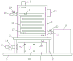
The utility model belongs to the technical field of boilers, and particularly discloses a device for recycling waste heat of discharged smoke of a boiler in a thermal power plant, which comprises a bottom plate, wherein a supporting plate is arranged above the bottom plate through a bracket, and a waste heat recovery box is arranged at the top of the supporting plate; the top of the bottom plate is provided with a flue gas purification box, and one side of the bottom plate is provided with a heat preservation water tank; a smoke inlet pipe is arranged on one side of the smoke purifying box, a smoke outlet pipe is arranged on the top of the other side of the smoke purifying box, and the top end of the smoke outlet pipe is communicated with the bottom of the waste heat recovery box; a filter screen plate and an active carbon adsorption plate are arranged inside the flue gas purification box, a taking and placing groove is arranged at the front side of the flue gas purification box, and a sealing piece is arranged in the taking and placing groove; one side of the waste heat recovery tank is provided with a water inlet pipe, the other side of the waste heat recovery tank is provided with a water outlet pipe, and the water outlet pipe is communicated with the heat preservation water tank; a waste heat absorption water pipe is arranged in the waste heat recovery tank, the top end of the waste heat absorption water pipe is communicated with the water inlet pipe, and the bottom end of the waste heat absorption water pipe is communicated with the water outlet pipe; the top of the waste heat recovery tank is provided with an exhaust pipe; the utility model discloses simple structure, and improved the utilization ratio of waste heat.
Description
Technical Field
The utility model relates to a boiler technical field specifically is a waste heat recovery recycles device of discharging fume of thermal power plant's boiler.
Background
The boiler is an energy conversion device which mainly converts chemical energy, electric energy and the like in fuel into heat energy and outputs high-temperature steam or an organic heat carrier through the boiler, wherein the boiler generating the steam is called as a steam boiler. The combustion of fuel generates a large amount of flue gas, the temperature of the flue gas is generally between 170 and 225 ℃, and the flue gas is directly exhausted through a flue gas exhaust pipe, so that a large amount of heat energy is lost.
Most of existing boiler smoke exhaust waste heat recycling devices heat water, but the water does not absorb heat any more after absorbing heat, and the utilization rate of waste heat is reduced.
SUMMERY OF THE UTILITY MODEL
An object of the utility model is to provide a waste heat recovery recycles device of discharging fume of thermal power plant's boiler to solve the problem that proposes in the above-mentioned background art.
In order to achieve the above object, the utility model provides a following technical scheme: a device for recycling waste heat of boiler exhaust smoke of a thermal power plant comprises a bottom plate, wherein a support plate is arranged above the bottom plate through a support, and a waste heat recycling box is arranged at the top of the support plate; a flue gas purification box is arranged below the supporting plate at the top of the bottom plate, and a heat preservation water tank is arranged at the top of one side of the bottom plate; a smoke inlet pipe is arranged on one side of the smoke purifying box, which is far away from the heat-preservation water tank, a smoke outlet pipe is arranged on the top of the other side of the smoke purifying box, and the top end of the smoke outlet pipe is communicated with the bottom of the waste heat recovery box; a filter screen plate and an active carbon adsorption plate are sequentially arranged inside the flue gas purification box from left to right, a taking and placing groove is formed in the front side of the flue gas purification box, and a sealing piece is arranged in the taking and placing groove; a water inlet pipe is arranged at the top of one side of the waste heat recovery tank, a water outlet pipe is arranged at the bottom of the other side of the waste heat recovery tank, and the water outlet pipe is communicated with the heat preservation water tank; a waste heat absorption water pipe is arranged in the waste heat recovery tank, the top end of the waste heat absorption water pipe is communicated with the water inlet pipe, and the bottom end of the waste heat absorption water pipe is communicated with the water outlet pipe; and an exhaust pipe is arranged at the top of the waste heat recovery tank.
Preferably, the smoke inlet pipe is provided with a fan, the air inlet end of the fan is communicated with the boiler smoke exhaust pipe, and the air outlet end of the fan is communicated with the smoke purification box.
Preferably, U-shaped draw-in grooves have all been seted up with the corresponding department of filtering screen plate and active carbon adsorption board to the upper and lower end of flue gas purification case inner chamber, and the upper and lower ends of filtering screen plate and active carbon adsorption board all are connected with U-shaped draw-in groove gomphosis.
Preferably, the sealing element comprises a sealing block, the sealing block is embedded in the taking and placing groove, U-shaped stabilizing grooves are formed in the inner end of the sealing block and the corresponding positions of the filter screen plate and the activated carbon adsorption plate, and the U-shaped stabilizing grooves are matched with the filter screen plate and the activated carbon adsorption plate; the outer end rigid coupling of sealed piece has the fixed plate, and the edge of fixed plate all is connected with gas cleaning case through the screw.
Preferably, a handle is mounted on the fixing plate.
Preferably, the waste heat absorption water pipe is arranged in a spiral mode, a liquid level sensor is installed at the top of an inner cavity of the waste heat absorption water pipe, and a temperature sensor is installed at the bottom end of the inner cavity.
Preferably, the water inlet pipe is provided with a water inlet control valve, and the water outlet pipe is provided with a water outlet control valve.
Preferably, a controller is installed on the outer side wall of the waste heat recovery tank, and the controller is electrically connected with the liquid level sensor, the temperature sensor, the water inlet control valve and the water outlet control valve.
Preferably, a rubber pad is arranged between the taking and placing groove and the sealing block, and the rubber pad is in sliding connection with the sealing block.
Compared with the prior art, the beneficial effects of the utility model are that:
1. in the utility model, the flue gas purification box is arranged at the front end of the waste heat recovery box, so that the waste heat recovery can be carried out after the boiler flue gas is filtered and purified, the ash in the boiler flue gas is prevented from covering the waste heat absorption water pipe, and the heat transfer efficiency between the flue gas and the waste heat absorption water pipe can be improved; simultaneously, through getting to put the groove, getting to put the cooperation use of groove, screw, sealed piece, fixed plate etc. be convenient for take out and filter otter board and active carbon adsorption plate, and then be convenient for clear up, change filter otter board and active carbon adsorption plate, guaranteed the purifying effect who filters otter board and active carbon adsorption plate.
2. The utility model discloses in filter, the flue gas after the purification gets into the waste heat recovery case through going out the tobacco pipe, the heat in the waste heat absorption water pipe absorption flue gas, the temperature in the temperature sensor real-time detection waste heat absorption water pipe, and transmit to the controller, when reaching the setting value, the controller opens out the water control valve, it stores to keep warm in the holding water box with hot water discharge, level sensor detects the water level in the waste heat absorption water pipe, and transmit to the controller, when being less than the setting value, the controller is opened and is advanced the water control valve and introduce waste heat absorption water intraductal heat absorption once more with external cold water, so reciprocal circulation, recovery waste heat that can be better, improve the utilization ratio of waste heat.
Drawings
Fig. 1 is a schematic view of the overall structure of the present invention;
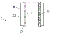
FIG. 2 is a schematic view of a partial internal structure of the flue gas purifying box of the present invention;
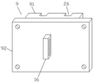
fig. 3 is a schematic structural diagram of the sealing member of the present invention.
In the figure: 1. a base plate; 2. a support; 3. a support plate; 4. a waste heat recovery tank; 5. a flue gas purification box; 6. a heat preservation water tank; 7. a smoke inlet pipe; 8. a taking and placing groove; 9. a seal member; 91. a sealing block; 92. a fixing plate; 93. a screw; 10. a water inlet pipe; 11. a water outlet pipe; 12. a waste heat absorption water pipe; 13. an exhaust pipe; 14. a fan; 15. a U-shaped clamping groove; 16. a handle; 17. a liquid level sensor; 18. a temperature sensor; 19. a water inlet control valve; 20. a water outlet control valve; 21. a controller; 22. a rubber pad; 23. a filter screen plate; 24. an activated carbon adsorption plate; 25. discharging the smoke tube; 26. u type steady groove.
Detailed Description
The technical solutions in the embodiments of the present invention will be described clearly and completely with reference to the accompanying drawings in the embodiments of the present invention, and it is obvious that the described embodiments are only some embodiments of the present invention, not all embodiments. Based on the embodiments in the present invention, all other embodiments obtained by a person skilled in the art without creative work belong to the protection scope of the present invention.
In the description of the present invention, it should be noted that the terms "vertical", "upper", "lower", "horizontal", and the like indicate orientations or positional relationships based on the orientations or positional relationships shown in the drawings, and are only for convenience of description and simplification of description, but do not indicate or imply that the device or element referred to must have a specific orientation, be constructed in a specific orientation, and be operated, and thus should not be construed as limiting the present invention.
In the description of the present invention, it should also be noted that, unless otherwise explicitly specified or limited, the terms "disposed," "mounted," "connected," and "connected" are to be construed broadly, e.g., as meaning either a fixed connection, a removable connection, or an integral connection; can be mechanically or electrically connected; they may be connected directly or indirectly through intervening media, or they may be interconnected between two elements. The specific meaning of the above terms in the present invention can be understood according to specific situations by those skilled in the art.
Referring to fig. 1-3, the present invention provides a technical solution: a device for recycling waste heat of boiler exhaust smoke of a thermal power plant comprises a bottom plate 1, wherein a support plate 3 is arranged above the bottom plate 1 through a support 2, and a waste heat recycling box 4 is arranged at the top of the support plate 3; a flue gas purification box 5 is arranged below the supporting plate 3 at the top of the bottom plate 1, and a heat preservation water tank 6 is arranged at the top of one side of the bottom plate 1; a smoke inlet pipe 7 is arranged on one side of the smoke purifying box 5 away from the heat preservation water tank 6, a smoke outlet pipe 25 is arranged on the top of the other side of the smoke purifying box, and the top end of the smoke outlet pipe 25 is communicated with the bottom of the waste heat recovery box 4; a filter screen plate 23 and an active carbon adsorption plate 24 are sequentially arranged inside the flue gas purification box 5 from left to right, a taking and placing groove 8 is formed in the front side of the flue gas purification box 5, and a sealing element 9 is arranged in the taking and placing groove 8; a water inlet pipe 10 is arranged at the top of one side of the waste heat recovery tank 4, a water outlet pipe 11 is arranged at the bottom of the other side of the waste heat recovery tank 4, and the water outlet pipe 11 is communicated with the heat preservation water tank 6; a waste heat absorption water pipe 12 is arranged in the waste heat recovery tank 4, the top end of the waste heat absorption water pipe 12 is communicated with a water inlet pipe 10, and the bottom end of the waste heat absorption water pipe is communicated with a water outlet pipe 11; and an exhaust pipe 13 is arranged at the top of the waste heat recovery tank 4.
Further, a fan 14 is installed on the smoke inlet pipe 7, an air inlet end of the fan 14 is communicated with the boiler smoke exhaust pipe, and an air outlet end of the fan 14 is communicated with the smoke purification box 5.
Further, U-shaped draw-in groove 15 has all been seted up with the corresponding department of filtering otter board 23 and active carbon adsorption board 24 to the upper and lower end of 5 inner chambers of flue gas purification case, and filters otter board 23 and active carbon adsorption board 24's upper and lower end and all is connected with U-shaped draw-in groove 15 gomphosis.
Further, the sealing element 9 comprises a sealing block 91, the sealing block 91 is embedded in the taking and placing groove 8, U-shaped stabilizing grooves 26 are formed in the inner end of the sealing block 91 and the corresponding positions of the filter screen plate 23 and the activated carbon adsorption plate 24, and the U-shaped stabilizing grooves 26 are matched with the filter screen plate 23 and the activated carbon adsorption plate 24; the outer end rigid coupling of sealed piece 91 has fixed plate 92, and the edge of fixed plate 92 all is connected with gas cleaning box 5 through screw 93.
Further, the handle 16 is mounted on the fixing plate 92.
Further, the waste heat absorption water pipe 12 is arranged in a spiral mode, a liquid level sensor 17 is installed at the top of an inner cavity of the waste heat absorption water pipe 12, and a temperature sensor 18 is installed at the bottom end of the inner cavity.
Further, a water inlet control valve 19 is installed on the water inlet pipe 10, and a water outlet control valve 20 is installed on the water outlet pipe 11.
Further, install controller 21 on the lateral wall of waste heat recovery case 4, controller 21 and level sensor 17, temperature sensor 18, water control valve 19 and water control valve 20 are electric connection.
Further, a rubber pad 22 is arranged between the taking and placing groove 8 and the sealing block 91, and the rubber pad 22 is in sliding connection with the sealing block 91.
The working principle is as follows: when the device is used, the smoke inlet pipe 7 is stably and correspondingly connected with a boiler discharge flue, the boiler smoke is quickly guided into the smoke purification box 5 through the fan 14, the smoke is filtered and purified through the filter screen plate 23 and the activated carbon adsorption plate 24, the filtered and purified smoke enters the waste heat recovery box 4 through the smoke outlet pipe 25, the waste heat absorption water pipe 12 absorbs heat in the smoke, the temperature sensor 18 detects the water temperature in the waste heat absorption water pipe 12 in real time and transmits the water temperature to the controller 21, when a set value is reached, the controller 21 opens the water outlet control valve 20, hot water is discharged into the heat preservation water tank 6 for heat preservation and storage, the liquid level sensor 17 detects the water level in the waste heat absorption water pipe 12 and transmits the water level to the controller 21, when the water level is lower than the set value, the controller 21 opens the water inlet valve 19 to introduce external cold water into the waste heat absorption water pipe 12 for heat absorption again, and the cycle is repeated in such a way, the waste heat can be better recovered, the utilization rate of the waste heat is improved, the flue gas purification box 5 is arranged at the front end of the waste heat recovery box 4, the waste heat recovery can be carried out after the boiler flue gas is filtered and purified, the phenomenon that the soot in the boiler flue gas covers the waste heat absorption water pipe 12 is avoided, and the heat transfer efficiency between the flue gas and the waste heat absorption water pipe 12 can be improved;
when clearing up, change filter plate 23 and active carbon adsorption plate 24, dismantle screw 93, remove the fixed to fixed plate 92, drive sealed piece 91 through handle 16 and fixed plate 92 and move to the outside, and then can make sealed piece 91 take out from getting to put in groove 8, take out the back, can take out filter plate 23 and active carbon adsorption plate 24 from U type draw-in groove 15, and is simple in operation, it is convenient to dismantle filter plate 23 and active carbon adsorption plate 24, and then, conveniently clear up, change filter plate 23 and active carbon adsorption plate 24, the purifying effect who has guaranteed filter plate 23 and active carbon adsorption plate 24.
It is worth noting that: the whole device realizes control over the device through the master control button, and the device matched with the control button is common equipment, belongs to the existing mature technology, and is not repeated for the electrical connection relation and the specific circuit structure.
Although embodiments of the present invention have been shown and described, it will be appreciated by those skilled in the art that changes, modifications, substitutions and alterations can be made in these embodiments without departing from the principles and spirit of the invention, the scope of which is defined in the appended claims and their equivalents.
Claims (9)
1. The device for recycling the waste heat of the discharged smoke of the boiler in the thermal power plant is characterized by comprising a bottom plate (1), wherein a support plate (3) is arranged above the bottom plate (1) through a support (2), and a waste heat recycling box (4) is arranged at the top of the support plate (3); a flue gas purification box (5) is arranged below the supporting plate (3) at the top of the bottom plate (1), and a heat preservation water tank (6) is arranged at the top of one side of the bottom plate (1); a smoke inlet pipe (7) is arranged on one side of the smoke purifying box (5) far away from the heat preservation water tank (6), a smoke outlet pipe (25) is arranged at the top of the other side of the smoke purifying box, and the top end of the smoke outlet pipe (25) is communicated with the bottom of the waste heat recovery box (4); a filter screen plate (23) and an active carbon adsorption plate (24) are sequentially arranged inside the flue gas purification box (5) from left to right, a taking and placing groove (8) is formed in the front side of the flue gas purification box (5), and a sealing piece (9) is arranged in the taking and placing groove (8); a water inlet pipe (10) is arranged at the top of one side of the waste heat recovery tank (4), a water outlet pipe (11) is arranged at the bottom of the other side of the waste heat recovery tank, and the water outlet pipe (11) is communicated with the heat preservation water tank (6); a waste heat absorption water pipe (12) is arranged in the waste heat recovery tank (4), the top end of the waste heat absorption water pipe (12) is communicated with the water inlet pipe (10), and the bottom end of the waste heat absorption water pipe is communicated with the water outlet pipe (11); and an exhaust pipe (13) is arranged at the top of the waste heat recovery tank (4).
2. The device for recycling waste heat of exhaust smoke of a boiler in a thermal power plant according to claim 1, characterized in that: the smoke inlet pipe (7) is provided with a fan (14), the air inlet end of the fan (14) is communicated with the boiler smoke exhaust pipe, and the air outlet end of the fan (14) is communicated with the smoke purification box (5).
3. The device for recycling waste heat of exhaust smoke of a boiler in a thermal power plant according to claim 1, characterized in that: u-shaped draw-in groove (15) have all been seted up with the department that corresponds of filtering screen plate (23) and active carbon adsorption board (24) to the last lower extreme of gas cleaning case (5) inner chamber, and the upper and lower end of filtering screen plate (23) and active carbon adsorption board (24) all is connected with U-shaped draw-in groove (15) gomphosis.
4. The device for recycling waste heat of exhaust smoke of a boiler in a thermal power plant according to claim 1, characterized in that: the sealing element (9) comprises a sealing block (91), the sealing block (91) is embedded with the taking and placing groove (8) and is arranged, U-shaped stabilizing grooves (26) are formed in the inner end of the sealing block (91) and the corresponding positions of the filter screen plate (23) and the activated carbon adsorption plate (24), and the U-shaped stabilizing grooves (26) are matched with the filter screen plate (23) and the activated carbon adsorption plate (24); the outer end rigid coupling of sealed piece (91) has fixed plate (92), and the corner of fixed plate (92) all is connected with gas cleaning case (5) through screw (93).
5. The heat recovery and reuse device of the exhaust smoke waste heat of the boiler of the thermal power plant according to claim 4, characterized in that: the fixed plate (92) is provided with a handle (16).
6. The device for recycling waste heat of exhaust smoke of a boiler in a thermal power plant according to claim 1, characterized in that: the waste heat absorption water pipe (12) is arranged in a spiral mode, a liquid level sensor (17) is installed at the top of an inner cavity of the waste heat absorption water pipe (12), and a temperature sensor (18) is installed at the bottom end of the inner cavity.
7. The device for recycling waste heat of exhaust smoke of a boiler in a thermal power plant according to claim 1, characterized in that: and a water inlet control valve (19) is installed on the water inlet pipe (10), and a water outlet control valve (20) is installed on the water outlet pipe (11).
8. The device for recycling waste heat of exhaust smoke of a boiler in a thermal power plant according to claim 1, characterized in that: install controller (21) on the lateral wall of waste heat recovery case (4), controller (21) and level sensor (17), temperature sensor (18), water control valve (19) and play water control valve (20) are electric connection.
9. The device for recycling waste heat of exhaust smoke of a boiler in a thermal power plant according to claim 1, characterized in that: a rubber pad (22) is arranged between the taking and placing groove (8) and the sealing block (91), and the rubber pad (22) is in sliding connection with the sealing block (91).
Priority Applications (1)
| Application Number | Priority Date | Filing Date | Title |
|---|---|---|---|
| CN202022937858.4U CN214009262U (en) | 2020-12-10 | 2020-12-10 | Boiler of thermal power plant exhaust smoke waste heat recovery recycles device |
Applications Claiming Priority (1)
| Application Number | Priority Date | Filing Date | Title |
|---|---|---|---|
| CN202022937858.4U CN214009262U (en) | 2020-12-10 | 2020-12-10 | Boiler of thermal power plant exhaust smoke waste heat recovery recycles device |
Publications (1)
| Publication Number | Publication Date |
|---|---|
| CN214009262U true CN214009262U (en) | 2021-08-20 |
Family
ID=77310186
Family Applications (1)
| Application Number | Title | Priority Date | Filing Date |
|---|---|---|---|
| CN202022937858.4U Active CN214009262U (en) | 2020-12-10 | 2020-12-10 | Boiler of thermal power plant exhaust smoke waste heat recovery recycles device |
Country Status (1)
| Country | Link |
|---|---|
| CN (1) | CN214009262U (en) |
-
2020
- 2020-12-10 CN CN202022937858.4U patent/CN214009262U/en active Active
Similar Documents
| Publication | Publication Date | Title |
|---|---|---|
| CN213656782U (en) | Heat accumulating type thermal oxidizer | |
| CN212915042U (en) | Cremator exhaust gas purification system | |
| CN214009262U (en) | Boiler of thermal power plant exhaust smoke waste heat recovery recycles device | |
| CN217843882U (en) | RTO heat accumulating type oxidation incineration exhaust gas treatment system | |
| CN211146512U (en) | Compact RTO heat accumulating type thermal combustion device | |
| CN212300022U (en) | Waste gas waste heat recovery system of coal-fired boiler | |
| CN213237978U (en) | Energy-saving and environment-friendly boiler with waste heat recovery device | |
| CN210979795U (en) | Horizontal two-stage energy saver | |
| CN218553483U (en) | Flue gas purification device for condensation module boiler | |
| CN220524144U (en) | Heat exchange structure and fuel oil and gas boiler | |
| CN220287735U (en) | Clean energy heating device | |
| CN213453704U (en) | Heat pipe type waste heat boiler | |
| CN214502191U (en) | Waste heat recovery device for chemical processing | |
| CN220852598U (en) | Energy-saving emission-reducing gas boiler | |
| CN213392668U (en) | Novel screw compressor blowdown device | |
| CN218544494U (en) | Flue gas waste heat recovery device of gas turbine power plant gas turbine boiler | |
| CN219367757U (en) | Energy-saving heating system | |
| CN210814388U (en) | Flue gas treatment device capable of recovering heat | |
| CN212456935U (en) | Thermal power generation boiler capable of recovering heat energy | |
| CN213983639U (en) | Incineration boiler flue gas recovery device | |
| CN215570567U (en) | Boiler flue gas waste heat utilization equipment | |
| CN220345467U (en) | Pressurized carbon dioxide absorbing and trapping system | |
| CN211575522U (en) | Environment-friendly self-loopa condensation boiler unit | |
| CN216667701U (en) | Oil gas recovery burns device | |
| CN213840981U (en) | Boiler waste heat recovery device |
Legal Events
| Date | Code | Title | Description |
|---|---|---|---|
| GR01 | Patent grant | ||
| GR01 | Patent grant |