CN214000979U - Packaging carton outward appearance printing spraying device - Google Patents
Packaging carton outward appearance printing spraying device Download PDFInfo
- Publication number
- CN214000979U CN214000979U CN202021822427.7U CN202021822427U CN214000979U CN 214000979 U CN214000979 U CN 214000979U CN 202021822427 U CN202021822427 U CN 202021822427U CN 214000979 U CN214000979 U CN 214000979U
- Authority
- CN
- China
- Prior art keywords
- printing
- box
- cylinder
- ink tank
- air
- Prior art date
- Legal status (The legal status is an assumption and is not a legal conclusion. Google has not performed a legal analysis and makes no representation as to the accuracy of the status listed.)
- Active
Links
Images
Landscapes
- Supply, Installation And Extraction Of Printed Sheets Or Plates (AREA)
Abstract
The utility model belongs to the technical field of the printing, especially, be a packing carton outward appearance printing spraying device, the power distribution box comprises a box body, the top of box is provided with printing ink tank, printing ink tank's top is provided with the printing ink tank mouth, printing ink tank one side is provided with conveyor, the box top is provided with the third cylinder. Run through the intercommunication with the extraction tube and ink tank through being connected of the pump body and extraction tube and carry the inside printing ink of ink tank to the sponge is inside to be absorbed by the conveyer pipe, furtherly, through the friction of printing roller and sponge with printing ink absorption on the printing roller surface, drive the rack through first cylinder and rotate at the inside slip drive gear of movable groove, thereby overturn the printing plate, furtherly, air-dry the printed matter, accelerate printing efficiency, fix the printed matter at the printing plate top through fixing bolt and guarantee that the printed matter can not change the position at will, improve printing efficiency, air-dry the printed matter of printing plate inside fixing through air-dry mechanism.
Description
Technical Field
The utility model belongs to the technical field of the printing, concretely relates to packing carton outward appearance printing spraying device.
Background
Printing is a technique of transferring ink to the surface of a material such as paper, fabric, plastic, or leather by performing processes such as plate making, inking, and pressing on an original such as characters, pictures, photographs, or forgery prevention, and thereby mass-transferring the content of the original.
However, the conventional printing apparatus cannot print an article in a large area, and needs to print many times, which reduces printing efficiency, and in addition, the printing apparatus is often affected by the printed matter being offset during printing due to the poor fixation to the printed matter during printing, and the printed writing is blurred due to the ink discharge during printing.
SUMMERY OF THE UTILITY MODEL
To solve the problems set forth in the background art described above. The utility model provides a packing carton outward appearance printing spraying device has solved and has printed article that can not be by a large scale, need print many times, makes the problem of the efficiency reduction of printing.
In order to achieve the above object, the utility model provides a following technical scheme: the utility model provides a packing carton outward appearance printing spraying device, includes the box, the top of box is provided with ink tank, ink tank's top is provided with the ink tank mouth, ink tank one side is provided with conveyor, the box top is provided with the third cylinder, the bottom of third cylinder is provided with the second gas pole, the bottom of second gas pole is provided with the template, one side of box is provided with the second cylinder, one side of second cylinder is provided with the fixed plate, one side of fixed plate is provided with first gas pole, the one end of first gas pole is provided with the printing roller, the outside of printing roller is provided with the spout, one side of box is provided with first cylinder, one side of first cylinder is provided with the rack, the top of rack is provided with the gear, one side of gear is provided with the pivot, the outside of pivot is provided with the printing plate, the printing plate is characterized in that a fixing bolt is arranged inside the printing plate, an air drying mechanism is arranged at the bottom of the box body, an air outlet is formed in the positive portion of the box body, and a movable groove is formed in the outer portion of the rack.
Preferably, conveyor includes the pump body, one side of the pump body is provided with the extraction pipe, the opposite side of the pump body is provided with the conveyer pipe, the one end of conveyer pipe is provided with the sponge.
Preferably, the rack and the gear are installed in a matched mode, and one end of the rack is fixedly connected to one side of the first air cylinder.
Preferably, the number of the air drying mechanisms is two, and the two air drying mechanisms are symmetrically arranged at the bottom of the box body.
Preferably, the number of the fixing bolts is four, and the four fixing bolts are uniformly arranged inside the printing plate.
Preferably, the rotating shaft is fixedly installed inside the printing plate, and the rack slides inside the movable groove.
Compared with the prior art, the beneficial effects of the utility model are that:
run through the intercommunication with the extraction tube and ink tank through being connected of the pump body and extraction tube and carry the inside printing ink of ink tank to the sponge is inside to be absorbed by the conveyer pipe, furtherly, through the friction of printing roller and sponge with printing ink absorption on the printing roller surface, drive the rack through first cylinder and rotate at the inside slip drive gear of movable groove, thereby overturn the printing plate, furtherly, air-dry the printed matter, accelerate printing efficiency, fix the printed matter at the printing plate top through fixing bolt and guarantee that the printed matter can not change the position at will, improve printing efficiency, air-dry the printed matter of printing plate inside fixing through air-dry mechanism.
Drawings
The accompanying drawings are included to provide a further understanding of the invention, and are incorporated in and constitute a part of this specification, illustrate embodiments of the invention, and together with the description serve to explain the invention and not to limit the invention. In the drawings:
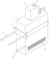
fig. 1 is a complete structural schematic diagram of the present invention;
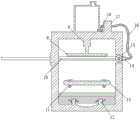
FIG. 2 is a front sectional view of the present invention;
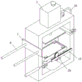
FIG. 3 is a three-dimensional cross-sectional structure of the present invention;
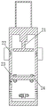
fig. 4 is a side view profile structure of the present invention.
In the figure: 1, a box body; 2 an ink tank; 3 ink tank port; 4, air outlet; 5 a first cylinder; 6 a second cylinder; 7 fixing the plate; 8 a third cylinder; 9, template; 10 a first gas lever; 11 fixing the bolt; 12 air drying mechanism; 13 a printing plate; 14 a sponge; 15 a printing roller; 16 conveying pipes; 17 a pump body; 18 an extraction tube; 19 a rack; 20 gears; 21 a second air rod; 22 chute; 23, a movable groove; 24 rotating the shaft.
Detailed Description
The technical solutions in the embodiments of the present invention will be described clearly and completely with reference to the accompanying drawings in the embodiments of the present invention, and it is obvious that the described embodiments are only some embodiments of the present invention, not all embodiments. Based on the embodiments in the present invention, all other embodiments obtained by a person skilled in the art without creative work belong to the protection scope of the present invention.
Referring to fig. 1-4, the present invention provides the following technical solutions: a printing and spraying device for the appearance of a packaging carton comprises a box body 1, wherein an ink box 2 is arranged at the top of the box body 1, an ink box opening 3 is formed in the top of the ink box 2, a conveying device is arranged on one side of the ink box 2, a third air cylinder 8 is arranged at the top of the box body 1, a second air rod 21 is arranged at the bottom of the third air cylinder 8, a template 9 is arranged at the bottom end of the second air rod 21, a second air cylinder 6 is arranged on one side of the box body 1, a fixing plate 7 is arranged on one side of the second air cylinder 6, a first air rod 10 is arranged on one side of the fixing plate 7, a printing roller 15 is arranged at one end of the first air rod 10, a sliding groove 22 is formed in the outer portion of the printing roller 15, a first air cylinder 5 is arranged on one side of the box body 1, a rack 19 is arranged on one side of the first air cylinder 5, a gear 20 is arranged at the top of the rack 19, a rotating shaft 24 is arranged on one side of the gear 20, and a printing plate 13 is arranged on the outer portion of the rotating shaft 24, the interior of the printing plate 13 is provided with a fixing bolt 11, the bottom of the box body 1 is provided with an air drying mechanism 12, the positive part of the box body 1 is provided with an air outlet 4, and the exterior of the rack 19 is provided with a movable groove 23.
In this embodiment, run through the intercommunication with extraction tube 18 and ink tank 2 through being connected through the pump body 17 and extraction tube 18 and carry the inside printing ink of ink tank 2 to the inside absorption of sponge 14 by conveyer pipe 16, furtherly, through the friction of printing roller 15 with sponge 14 with printing ink absorption on printing roller 15 surface, drive rack 19 through first cylinder 5 and drive gear 20 rotation at the inside slip of movable groove 23, thereby overturn printing plate 13, furtherly, air-dry the printed matter, accelerate printing efficiency, fix the printed matter at printing plate 13 top through fixing bolt 11 and guarantee that the printed matter can not change the position at will, printing efficiency is improved, air-dry the printed matter of printing plate 13 inside fixation through air-dry mechanism 12.
Specifically, the conveying device comprises a pump body 17, an extraction pipe 18 is arranged on one side of the pump body 17, a conveying pipe 16 is arranged on the other side of the pump body 17, a sponge 14 is arranged at one end of the conveying pipe 16, the extraction pipe 18 and the ink tank 2 are communicated through the pump body 17 and the extraction pipe 18, ink inside the ink tank 2 is conveyed to the sponge 14 through the conveying pipe 16 to be absorbed, and further the ink is adsorbed on the surface of the printing roller 15 through friction between the printing roller 15 and the sponge 14.
Specifically, rack 19 and gear 20 adaptation installation, rack 19 one end are fixed even in first cylinder 5 one side, drive rack 19 through first cylinder 5 and rotate at the inside slip drive gear 20 of activity groove 23 to overturn printing plate 13, further, air-dry the printed matter for printing efficiency.
Specifically, the number of the air drying mechanisms 12 is two, the two air drying mechanisms 12 are symmetrically arranged at the bottom of the box body 1, and the printed matter fixed inside the printing plate 13 is dried through the air drying mechanisms 12.
Specifically, fixing bolt 11's quantity is four, and four fixing bolt 11 evenly set up inside printing plate 13, fix the printed matter at printing plate 13 top through fixing bolt 11 and guarantee that the printed matter can not change the position at will, improve printing efficiency.
Specifically, the rotating shaft 24 is fixedly installed inside the printing plate 13, the rack 19 slides inside the movable groove 23, and the first cylinder 5 drives the rack 19 to slide inside the movable groove 23 to drive the gear 20 to rotate, so that the printing plate 13 is turned over.
The utility model discloses a theory of operation and use flow: after the utility model is installed, when in use, the required ink is poured into the ink box 2 through the ink box port 3, the extracting tube 18 is communicated with the ink box 2 through the connection of the pump body 17 and the extracting tube 18, the ink in the ink box 2 is conveyed to the sponge 14 for absorption through the conveying pipe 16, furthermore, the ink is adsorbed on the surface of the printing roller 15 through the friction between the printing roller 15 and the sponge 14, the printing roller 15 is driven to move in the chute 22 through the second air cylinder 6 and the first air rod 10 to contact the printing roller 15 and the template 9, further, the ink on the surface of the printing roller 15 is brushed on the template 9, the template 9 is driven to be close to the printing plate 13 for printing of the fixed printed matter through the third air cylinder 8 and the second air rod 21, the rack 19 is driven to slide in the movable groove 23 through the first printing plate cylinder 5 to drive the gear 20 to rotate, thereby turning the printing plate 13, further, air-dry the printed matter for printing efficiency fixes the printed matter at printing plate 13 top through fixing bolt 11 and guarantees that the printed matter can not change the position at will, improves printing efficiency, air-dries the printed matter of printing plate 13 internal fixation through air-drying mechanism 12.
Finally, it should be noted that: although the present invention has been described in detail with reference to the foregoing embodiments, it will be apparent to those skilled in the art that modifications may be made to the embodiments described in the foregoing embodiments, or equivalents may be substituted for elements thereof. Any modification, equivalent replacement, or improvement made within the spirit and principle of the present invention should be included in the protection scope of the present invention.
Claims (6)
1. The utility model provides a packing carton outward appearance printing spraying device, includes box (1), the top of box (1) is provided with printing ink box (2), its characterized in that: the top of ink tank (2) is provided with ink tank mouth (3), ink tank (2) one side is provided with conveyor, box (1) top is provided with third cylinder (8), the bottom of third cylinder (8) is provided with second gas pole (21), the bottom of second gas pole (21) is provided with template (9), one side of box (1) is provided with second cylinder (6), one side of second cylinder (6) is provided with fixed plate (7), one side of fixed plate (7) is provided with first gas pole (10), the one end of first gas pole (10) is provided with printing roller (15), the outside of printing roller (15) is provided with spout (22), one side of box (1) is provided with first cylinder (5), one side of first cylinder (5) is provided with rack (19), the top of rack (19) is provided with gear (20), one side of gear (20) is provided with pivot (24), the outside of pivot (24) is provided with printing plate (13), the inside of printing plate (13) is provided with fixing bolt (11), the bottom of box (1) is provided with air-dry mechanism (12), the portion of box (1) is provided with air outlet (4), the outside of rack (19) is provided with activity groove (23).
2. A printing and spraying device for the exterior of a packaging carton as claimed in claim 1, wherein: the conveying device comprises a pump body (17), an extraction pipe (18) is arranged on one side of the pump body (17), a conveying pipe (16) is arranged on the other side of the pump body (17), and a sponge (14) is arranged at one end of the conveying pipe (16).
3. A printing and spraying device for the exterior of a packaging carton as claimed in claim 1, wherein: the rack (19) and the gear (20) are installed in a matched mode, and one end of the rack (19) is fixedly connected to one side of the first air cylinder (5).
4. A printing and spraying device for the exterior of a packaging carton as claimed in claim 1, wherein: the air drying mechanism (12) is two in number, and the two air drying mechanisms (12) are symmetrically arranged at the bottom of the box body (1).
5. A printing and spraying device for the exterior of a packaging carton as claimed in claim 1, wherein: the number of the fixing bolts (11) is four, and the four fixing bolts (11) are uniformly arranged inside the printing plate (13).
6. A printing and spraying device for the exterior of a packaging carton as claimed in claim 1, wherein: the rotating shaft (24) is fixedly arranged inside the printing plate (13), and the rack (19) slides inside the movable groove (23).
Priority Applications (1)
| Application Number | Priority Date | Filing Date | Title |
|---|---|---|---|
| CN202021822427.7U CN214000979U (en) | 2020-08-27 | 2020-08-27 | Packaging carton outward appearance printing spraying device |
Applications Claiming Priority (1)
| Application Number | Priority Date | Filing Date | Title |
|---|---|---|---|
| CN202021822427.7U CN214000979U (en) | 2020-08-27 | 2020-08-27 | Packaging carton outward appearance printing spraying device |
Publications (1)
| Publication Number | Publication Date |
|---|---|
| CN214000979U true CN214000979U (en) | 2021-08-20 |
Family
ID=77288164
Family Applications (1)
| Application Number | Title | Priority Date | Filing Date |
|---|---|---|---|
| CN202021822427.7U Active CN214000979U (en) | 2020-08-27 | 2020-08-27 | Packaging carton outward appearance printing spraying device |
Country Status (1)
| Country | Link |
|---|---|
| CN (1) | CN214000979U (en) |
Cited By (1)
| Publication number | Priority date | Publication date | Assignee | Title |
|---|---|---|---|---|
| CN115782388A (en) * | 2023-01-09 | 2023-03-14 | 江苏汉印机电科技股份有限公司 | Multi-station printing equipment |
-
2020
- 2020-08-27 CN CN202021822427.7U patent/CN214000979U/en active Active
Cited By (1)
| Publication number | Priority date | Publication date | Assignee | Title |
|---|---|---|---|---|
| CN115782388A (en) * | 2023-01-09 | 2023-03-14 | 江苏汉印机电科技股份有限公司 | Multi-station printing equipment |
Similar Documents
| Publication | Publication Date | Title |
|---|---|---|
| CN214000979U (en) | Packaging carton outward appearance printing spraying device | |
| CN110802926B (en) | Double-sided printing machine for carton raw materials | |
| CN110774730A (en) | Automatic ink supply printing equipment | |
| CN208666231U (en) | A kind of gold stamping film conveying device | |
| CN208438862U (en) | A kind of flexible plate printer | |
| CN204472075U (en) | A kind of ink reservoir mechanism of intaglio press | |
| CN208630088U (en) | Drying device of printing machine | |
| CN208543935U (en) | A kind of set composite of perfecting press | |
| CN207059468U (en) | A kind of offset print of printed on both sides | |
| CN207726126U (en) | A kind of automatic imprinting apparatus | |
| CN212046431U (en) | Green printing drying device | |
| CN206765560U (en) | Ink retracting device for printing machine | |
| CN107150497A (en) | A kind of environmental protection printing machine | |
| CN208469276U (en) | Gravure printing apparatus | |
| CN213199168U (en) | Printing mechanism of rotary press | |
| CN213920179U (en) | Carton printing machine is with evenly scribbling black device | |
| CN206231064U (en) | A kind of print cartridge of tight locking button and chip carrier disjunctor | |
| CN220198819U (en) | Printing device for lining paper printing | |
| CN206927334U (en) | A kind of transport mechanism of batch (-type) rotary press | |
| CN206536960U (en) | A kind of few printing equipment of process | |
| CN206645589U (en) | A kind of printing machine paper feed mechanism | |
| CN219446474U (en) | Intelligent anti-counterfeiting digital printer | |
| CN210970312U (en) | Energy-saving printing machine | |
| CN211843712U (en) | Robot arm of multi-medium digital printing machine | |
| CN217892238U (en) | Energy-saving printing device |
Legal Events
| Date | Code | Title | Description |
|---|---|---|---|
| GR01 | Patent grant | ||
| GR01 | Patent grant |