CN213982727U - Instrument elevating gear is used in geographical mapping - Google Patents
Instrument elevating gear is used in geographical mapping Download PDFInfo
- Publication number
- CN213982727U CN213982727U CN202023320117.8U CN202023320117U CN213982727U CN 213982727 U CN213982727 U CN 213982727U CN 202023320117 U CN202023320117 U CN 202023320117U CN 213982727 U CN213982727 U CN 213982727U
- Authority
- CN
- China
- Prior art keywords
- backup pad
- surveying instrument
- instrument body
- fixed
- pivot
- Prior art date
- Legal status (The legal status is an assumption and is not a legal conclusion. Google has not performed a legal analysis and makes no representation as to the accuracy of the status listed.)
- Expired - Fee Related
Links
Images


Landscapes
- Position Fixing By Use Of Radio Waves (AREA)
Abstract
The utility model discloses an instrument elevating gear is used in geographical mapping, including the backup pad, the middle part on backup pad top is connected with the surveying instrument body through the fine setting subassembly, is equipped with the protection subassembly in the backup pad, and the bottom fixed mounting of backup pad is three to being the regulating plate that the annular distributes, and three are rotated respectively to the inside of regulating plate and alternate and install three second pivot, and the middle part of three second pivot is fixed the cover respectively and is equipped with three bull stick, the beneficial effects of the utility model are that: slide and the bull stick drives the pivot and rotate on the regulating plate on the bull stick through adjusting a section of thick bamboo, make the backup pad keep the level and adjust the rough height of surveying instrument body on the ground of unevenness, the surveying instrument body of being convenient for measures, carry out high fine setting through the fine setting subassembly, further improve the measuring accuracy of surveying instrument body, the damage of surveying instrument body bump when preventing to remove equipment through the protection subassembly, improve the life of surveying instrument body.
Description
Technical Field
The utility model relates to an instrument elevating gear, in particular to instrument elevating gear is used in geographical mapping belongs to geographical mapping instrument technical field.
Background
The surveying and mapping literal is understood as measuring and mapping, which is based on computer technology, photoelectric technology, network communication technology, space science and information science, takes a global navigation satellite positioning system, remote sensing and geographic information system as technical cores, selects the existing characteristic points and boundary lines on the ground and obtains the graph and position information reflecting the current situation of the ground by a measuring means, and is used for engineering construction, planning and design and administrative management. Geomapping instruments generally need to be used in conjunction with a lifting device.
Present instrument elevating gear for geographical survey can only roughly adjust the height of surveying instrument, can't carry out accurate fine setting, and surveying instrument measuring precision is not high, and elevating gear does not have protect function to the surveying instrument simultaneously, and the surveying instrument is easy to take place the collision and is damaged when removing equipment, influences surveying instrument life.
SUMMERY OF THE UTILITY MODEL
An object of the utility model is to provide an instrument elevating gear is used in geographical mapping to solve the problem that the survey meter easily takes place to collide the damage when the elevating gear who proposes among the above-mentioned background art highly can't carry out accurate fine setting to the survey meter and remove to equipment.
In order to achieve the above object, the utility model provides a following technical scheme: an instrument lifting device for geographic mapping comprises a supporting plate, wherein the middle part of the top end of the supporting plate is connected with a mapper body through a fine adjustment assembly, the fine adjustment assembly comprises an equipment plate, a threaded cylinder and two sliding cylinders, the equipment plate is fixedly arranged at the bottom end of the mapper body, the threaded cylinder and the two sliding cylinders are respectively fixedly arranged at the middle part of the top end of the supporting plate and at two sides of the top end of the supporting plate, a lead screw is installed at the top end of the threaded cylinder in a threaded penetrating manner, the top end of the lead screw is rotatably connected with the middle part of the bottom end of the equipment plate, two sliding rods are installed at the top ends of the two sliding cylinders in a sliding penetrating manner respectively, the top ends of the two sliding rods are respectively fixedly connected with two sides of the bottom end of the equipment plate, an annular groove is formed in the outer ring at the top end of the supporting plate, a protection assembly is arranged on the supporting plate and comprises a first protection cover which is fixedly arranged at the side edge of the top end of the supporting plate, the top of first safety cover is rotated and is installed first pivot, fixed cover is equipped with the second safety cover in the first pivot, the bottom of second safety cover slides and alternates and set up in the inside of ring channel, one side fixed mounting of another avris of second safety cover has the fixed plate, fixed mounting has the fixture block on the fixed plate, the opposite side of another avris of first safety cover is seted up with the size assorted draw-in groove of fixture block, the bottom fixed mounting of backup pad is three to being the regulating plate that the annular distributes, and three rotate respectively to the inside of regulating plate and alternate and install three second pivot, and is three the middle part of second pivot is fixed the cover respectively and is equipped with three bull stick, and is three it is equipped with three regulation section of thick bamboo to slide the cover respectively on.
As an optimized technical scheme of the utility model, the fixed cover in top of lead screw is equipped with the fine setting ring.
As an optimal technical scheme of the utility model, two the bottom of slide bar is fixed mounting respectively has two limiting plates, two the limiting plate respectively with the inner wall sliding contact of two slide drums.
As an optimal technical scheme of the utility model, it is three the both ends of second pivot are threaded respectively and are alternated and install six stop collars.
As a preferred technical scheme of the utility model, it is three the top in the regulation section of thick bamboo outside is the screw thread interlude respectively and is installed three adjusting screw, and is three adjusting screw's head end contacts with three bull stick respectively.
As a preferred technical scheme of the utility model, it is three the bottom of adjusting a section of thick bamboo is fixed mounting three connecting plate, three respectively the bottom of connecting plate is fixed mounting three stabilizer blade respectively.
Compared with the prior art, the beneficial effects of the utility model are that: the utility model relates to an instrument lifting device for geographic mapping, which can keep a support plate horizontal on uneven ground and adjust the approximate height of a mapper body by sliding an adjusting cylinder on a rotating rod and driving the rotating shaft to rotate on an adjusting plate by the rotating rod, thereby facilitating the measurement of the mapper body; the height of the surveying instrument body on the equipment plate is driven to be finely adjusted after the height is roughly adjusted by rotating a screw rod in the fine adjustment assembly on the threaded cylinder, the equipment plate moves to drive a sliding rod to slide on a sliding cylinder, the surveying instrument body is prevented from inclining to one side after being adjusted, and the measuring accuracy of the surveying instrument body is further improved; rotate through the first pivot in the protection subassembly, drive the second safety cover and rotate along the ring channel, make the fixture block on the fixed plate insert the draw-in groove, with the protection of surveying instrument body inside the protective housing that is enclosed by first safety cover, second safety cover and backup pad, the damage of surveying instrument body bump when preventing to remove equipment improves the life of surveying instrument body.
Drawings
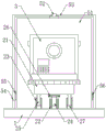
Fig. 1 is a schematic view of the overall structure of the present invention;
fig. 2 is a schematic front structural view of the present invention;
fig. 3 is a schematic view of the partial cross-sectional structure of the present invention.
In the figure: 1. a support plate; 2. a fine tuning component; 21. an equipment board; 22. a threaded barrel; 23. a slide cylinder; 24. a screw rod; 25. a slide bar; 26. a fine tuning ring; 27. a limiting plate; 3. a surveying instrument body; 4. an annular groove; 5. a protection component; 51. a first protective cover; 52. a first rotating shaft; 53. a second protective cover; 54. a fixing plate; 55. a clamping block; 56. a card slot; 6. an adjusting plate; 7. a second rotating shaft; 8. a rotating rod; 9. an adjusting cylinder; 10. a limiting sleeve; 11. adjusting the screw rod; 12. a connecting plate; 13. and (3) a support leg.
Detailed Description
The technical solutions in the embodiments of the present invention will be described clearly and completely with reference to the accompanying drawings in the embodiments of the present invention, and it is obvious that the described embodiments are only some embodiments of the present invention, not all embodiments. Based on the embodiments in the present invention, all other embodiments obtained by a person skilled in the art without creative work belong to the protection scope of the present invention.
Referring to fig. 1-3, the utility model provides an instrument lifting device for geography mapping, which comprises a supporting plate 1, the middle part of the top end of the supporting plate 1 is connected with a surveying instrument body 3 through a fine adjustment component 2, the fine adjustment component 2 comprises a device plate 21, a threaded cylinder 22 and two sliding cylinders 23, the device plate 21 is fixedly arranged at the bottom end of the surveying instrument body 3, the threaded cylinder 22 and the two sliding cylinders 23 are respectively fixedly arranged at the middle part and two sides of the top end of the supporting plate 1, a screw rod 24 is installed in a threaded manner at the top end of the threaded cylinder 22, the top end of the screw rod 24 is rotatably connected with the middle part of the bottom end of the device plate 21, two sliding rods 25 are respectively installed in a sliding manner at the top ends of the two sliding cylinders 23, the top ends of the two sliding rods 25 are respectively fixedly connected with two sides of the bottom end of the device plate 21, an annular groove 4 is arranged at the outer ring at the top end of the supporting plate 1, a protection component 5 is arranged on the supporting plate 1, the protection component 5 comprises a first protection cover 51, the first protection cover 51 is fixedly arranged on the side of the top end of the support plate 1, the top end of the first protection cover 51 is rotatably provided with a first rotating shaft 52, the first rotating shaft 52 is fixedly sleeved with a second protection cover 53, the bottom end of the second protection cover 53 is slidably inserted into the annular groove 4, one side of the other side of the second protection cover 53 is fixedly provided with a fixing plate 54, the fixing plate 54 is fixedly provided with a fixture block 55, the other side of the first protection cover 51 is provided with a clamping groove 56 matched with the size of the fixture block 55, the bottom end of the support plate 1 is fixedly provided with three pairs of adjusting plates 6 distributed in an annular shape, the three pairs of adjusting plates 6 are respectively rotatably inserted into the three second rotating shafts 7, the middle parts of the three second rotating shafts 7 are respectively and fixedly sleeved with three rotating rods 8, the three rotating rods 8 are respectively and slidably sleeved with three adjusting cylinders 9, the rotating rods 8 slide on the rotating rods 8 through the adjusting cylinders 9 and the rotating shafts are driven by the rotating rods 8 to rotate on the adjusting plates 6, the supporting plate 1 is kept horizontal on the uneven ground and the approximate height of the surveying instrument body 3 is adjusted, so that the surveying instrument body 3 can be conveniently measured, the lead screw 24 in the fine adjustment component 2 rotates on the threaded cylinder 22 to drive the surveying instrument body 3 on the equipment plate 21 to carry out height fine adjustment after the approximate height adjustment, the equipment plate 21 moves to drive the slide rod 25 to slide on the slide cylinder 23, the surveying instrument body 3 is prevented from inclining to one side after being adjusted, the measuring accuracy of the surveying instrument body 3 is further improved, the first rotating shaft 52 in the protection component 5 rotates to drive the second protection cover 53 to rotate along the annular groove 4, the clamping block 55 on the fixing plate 54 is inserted into the clamping groove 56, the surveying instrument body 3 is protected in the protection shell formed by the first protection cover 51, the second protection cover 53 and the supporting plate 1, and the surveying instrument body 3 is prevented from collision and damage when the equipment is moved, the service life of the surveying instrument body 3 is prolonged.
Preferably, a fine adjustment ring 26 is fixedly sleeved on the top of the screw rod 24, the screw rod 24 is conveniently rotated through the fine adjustment ring 26, two limiting plates 27 are fixedly installed at the bottom ends of the two sliding rods 25 respectively, the two limiting plates 27 are in sliding contact with the inner walls of the two sliding cylinders 23 respectively, the sliding rods 25 are prevented from sliding out of the sliding cylinders 23 through the limiting plates 27, the screw rod 24 is prevented from sliding out of the threaded cylinders 22, six limiting sleeves 10 are installed at two ends of the three second rotating shafts 7 in a threaded penetrating manner respectively, the rotating rods 8 are rotated to drive the second rotating shafts 7 to rotate, the rotating rods 8 are unfolded at proper angles, the unfolding angles of the rotating rods 8 are fixed through the limiting sleeves 10, three adjusting screws 11 are installed at the tops of the outer sides of the three adjusting cylinders 9 in a threaded penetrating manner respectively, the head ends of the three adjusting screws 11 are in contact with the three rotating rods 8 respectively, the adjusting cylinders 9 are fixed after being adjusted in a sliding manner on the rotating rods 8 through the adjusting screws 11, the bottom of three regulation section of thick bamboo 9 is fixed mounting three connecting plate 12 respectively, and the bottom of three connecting plate 12 is fixed mounting three stabilizer blade 13 respectively, steps on connecting plate 12 through the foot when setting up equipment on comparatively soft soil, inserts stabilizer blade 13 in the soil, improve equipment setting's stability.
When the lifting device is used, the utility model relates to an instrument lifting device for geography mapping, firstly, the whole equipment is placed on the ground, the rotating rod 8 is rotated to drive the second rotating shaft 7 to rotate, after the rotating rod 8 is unfolded by a proper angle, the unfolding angle of the rotating rod 8 is fixed through the limiting sleeve 10, the adjusting cylinder 9 slides on the rotating rod 8 and the rotating rod 8 drives the rotating shaft to rotate on the adjusting plate 6, so that the support plate 1 is kept horizontal on the uneven ground and the approximate height of the surveying instrument body 3 is adjusted, the adjusting cylinder 9 is fixed after sliding adjustment on the rotating rod 8 through the adjusting screw rod 11, when the placed ground is soft, a user steps on the connecting plate 12 through feet, inserts the support feet 13 into the ground, the stability of equipment erection is improved, then the fine adjustment ring 26 in the fine adjustment component 2 is rotated to drive the screw rod 24 to rotate on the threaded cylinder 22, the surveying instrument body 3 on the equipment plate 21 is driven to perform fine adjustment after the approximate height is adjusted, equipment board 21 removes and drives slide bar 25 and slide on smooth section of thick bamboo 23, prevent surveying instrument body 3 and adjust back lopsidedness, further improve surveying instrument body 3 measuring accuracy, limiting plate 27 of slide bar 25 bottom prevents slide bar 25 roll-off smooth section of thick bamboo 23, and then prevent lead screw 24 roll-off screw thread section of thick bamboo 22, when measuring after finishing to remove equipment, rotate through first pivot 52 in the protection subassembly 5, it rotates to drive second safety cover 53 along ring channel 4, make fixture block 55 on the fixed plate 54 insert in draw-in groove 56, with surveying instrument body 3 protection by first safety cover 51, inside the protective housing that second safety cover 53 and backup pad 1 enclose, surveying instrument body 3 takes place the collision damage when preventing to removing equipment, improve surveying instrument body 3's life.
In the description of the present invention, it should be understood that the indicated orientation or positional relationship is based on the orientation or positional relationship shown in the drawings, and is only for convenience of description and simplification of description, and does not indicate or imply that the indicated device or element must have a particular orientation, be constructed and operated in a particular orientation, and thus should not be construed as limiting the present invention.
In the present invention, unless otherwise explicitly specified or limited, for example, it may be fixedly connected, detachably connected, or integrated; can be mechanically or electrically connected; they may be directly connected or indirectly connected through an intermediate medium, and may be connected through the inside of two elements or in an interaction relationship between two elements, unless otherwise specifically defined, and the specific meaning of the above terms in the present invention will be understood by those skilled in the art according to specific situations.
Although embodiments of the present invention have been shown and described, it will be appreciated by those skilled in the art that changes, modifications, substitutions and alterations can be made in these embodiments without departing from the principles and spirit of the invention, the scope of which is defined in the appended claims and their equivalents.
Claims (6)
1. The utility model provides an instrument elevating gear for geographical mapping, includes backup pad (1), its characterized in that, the middle part on backup pad (1) top is connected with surveying instrument body (3) through fine setting subassembly (2), fine setting subassembly (2) includes equipment board (21), screw section of thick bamboo (22) and two slide drums (23), equipment board (21) are fixed to be set up in the bottom of surveying instrument body (3), screw section of thick bamboo (22) and two slide drums (23) are fixed respectively and are set up in the middle part and the both sides of top of backup pad (1) top, screw rod (24) are installed to the top screw thread interlude of screw section of thick bamboo (22), the top of screw rod (24) is connected with the middle part rotation of equipment board (21) bottom, two slide drums (23) the top respectively the slip interlude install two slide bars (25), two slide bars (25) the top respectively with the both sides fixed connection of equipment board (21) bottom, the outer ring on backup pad (1) top has been seted up ring channel (4), be equipped with protection subassembly (5) on backup pad (1), protection subassembly (5) are including first safety cover (51), first safety cover (51) are fixed to be set up the avris on backup pad (1) top, first pivot (52) are installed in the top rotation of first safety cover (51), fixed cover is equipped with second safety cover (53) on first pivot (52), the bottom of second safety cover (53) slides to alternate and sets up in the inside of ring channel (4), one side fixed mounting of another avris of second safety cover (53) has fixed plate (54), fixed mounting has fixture block (55) on fixed plate (54), draw-in groove (56) with the size assorted of fixture block (55) are seted up to the opposite side of another avris of first safety cover (51), three pairs of regulating plate (6) that are the annular distribution of bottom fixed mounting of backup pad (1), three rotate respectively to the inside of regulating plate (6) and alternate and install three second pivot (7), three the middle part of second pivot (7) is fixed the cover respectively and is equipped with three bull stick (8), and is three it is equipped with three regulation section of thick bamboo (9) to slide the cover respectively on bull stick (8).
2. The apparatus lifting device for geographical mapping as claimed in claim 1, wherein: the top of the screw rod (24) is fixedly sleeved with a fine adjustment ring (26).
3. The apparatus lifting device for geographical mapping as claimed in claim 1, wherein: the bottom ends of the two sliding rods (25) are respectively and fixedly provided with two limiting plates (27), and the two limiting plates (27) are respectively in sliding contact with the inner walls of the two sliding cylinders (23).
4. The apparatus lifting device for geographical mapping as claimed in claim 1, wherein: and six limiting sleeves (10) are respectively threaded and inserted at two ends of the three second rotating shafts (7).
5. The apparatus lifting device for geographical mapping as claimed in claim 1, wherein: the top of the outer side of each adjusting cylinder (9) is provided with three adjusting screws (11) in a threaded penetrating mode, and the head ends of the three adjusting screws (11) are respectively in contact with the three rotating rods (8).
6. The apparatus lifting device for geographical mapping as claimed in claim 1, wherein: the bottom of three regulation section of thick bamboo (9) is fixed mounting respectively has three connecting plate (12), and is three the bottom of connecting plate (12) is fixed mounting respectively has three stabilizer blade (13).
Priority Applications (1)
| Application Number | Priority Date | Filing Date | Title |
|---|---|---|---|
| CN202023320117.8U CN213982727U (en) | 2020-12-31 | 2020-12-31 | Instrument elevating gear is used in geographical mapping |
Applications Claiming Priority (1)
| Application Number | Priority Date | Filing Date | Title |
|---|---|---|---|
| CN202023320117.8U CN213982727U (en) | 2020-12-31 | 2020-12-31 | Instrument elevating gear is used in geographical mapping |
Publications (1)
| Publication Number | Publication Date |
|---|---|
| CN213982727U true CN213982727U (en) | 2021-08-17 |
Family
ID=77250204
Family Applications (1)
| Application Number | Title | Priority Date | Filing Date |
|---|---|---|---|
| CN202023320117.8U Expired - Fee Related CN213982727U (en) | 2020-12-31 | 2020-12-31 | Instrument elevating gear is used in geographical mapping |
Country Status (1)
| Country | Link |
|---|---|
| CN (1) | CN213982727U (en) |
Cited By (4)
| Publication number | Priority date | Publication date | Assignee | Title |
|---|---|---|---|---|
| CN113958834A (en) * | 2021-10-12 | 2022-01-21 | 袁犁 | Coordinate acquisition device based on geographic information and use method thereof |
| CN114251580A (en) * | 2021-12-28 | 2022-03-29 | 范雷 | Fixed tripod of detection instrument convenient to leveling |
| CN114754240A (en) * | 2022-03-10 | 2022-07-15 | 韦通 | Mapping device for geographical planning based on image recognition technology |
| CN117739219A (en) * | 2023-12-19 | 2024-03-22 | 蒙阴县自然资源和规划局 | Surveying instrument positioning equipment and method for geographic information surveying |
-
2020
- 2020-12-31 CN CN202023320117.8U patent/CN213982727U/en not_active Expired - Fee Related
Cited By (7)
| Publication number | Priority date | Publication date | Assignee | Title |
|---|---|---|---|---|
| CN113958834A (en) * | 2021-10-12 | 2022-01-21 | 袁犁 | Coordinate acquisition device based on geographic information and use method thereof |
| CN114251580A (en) * | 2021-12-28 | 2022-03-29 | 范雷 | Fixed tripod of detection instrument convenient to leveling |
| CN114251580B (en) * | 2021-12-28 | 2024-06-28 | 湖南宇元工程检测有限公司 | Fixed tripod of detector convenient to leveling |
| CN114754240A (en) * | 2022-03-10 | 2022-07-15 | 韦通 | Mapping device for geographical planning based on image recognition technology |
| CN114754240B (en) * | 2022-03-10 | 2023-09-22 | 嘉兴市国土空间规划研究有限公司 | Mapping device for geographic planning based on image recognition technology |
| CN117739219A (en) * | 2023-12-19 | 2024-03-22 | 蒙阴县自然资源和规划局 | Surveying instrument positioning equipment and method for geographic information surveying |
| CN117739219B (en) * | 2023-12-19 | 2024-05-10 | 蒙阴县自然资源和规划局 | Surveying instrument positioning equipment and method for geographic information surveying |
Similar Documents
| Publication | Publication Date | Title |
|---|---|---|
| CN213982727U (en) | Instrument elevating gear is used in geographical mapping | |
| CN212510321U (en) | Positioning balance acquisition device for geographic mapping | |
| CN216383431U (en) | Surveying and mapping device for land arrangement | |
| CN112113112A (en) | Diversified rotatory A-frame of engineering surveying instrument | |
| KR101531025B1 (en) | Apparatus for protecting tripod in geodetic survey | |
| CN213271725U (en) | Mapping instrument positioning device for engineering mapping | |
| CN212960677U (en) | Survey and drawing measuring device is used to geography convenient to use | |
| CN117386947A (en) | Geographic information mapping equipment building platform and application method thereof | |
| CN216246372U (en) | High stability survey and drawing sighting rod that base is adjustable | |
| CN210344898U (en) | Horizontal testing device for real estate surveying and mapping | |
| CN214037663U (en) | On-spot mapping device of building engineering cost | |
| CN211853280U (en) | Omnibearing rotary GPS display | |
| CN220566923U (en) | Engineering survey and drawing support base | |
| CN214502471U (en) | Portable cadastral survey and drawing measuring device for land exploration | |
| CN213872047U (en) | On-spot mapping device of building engineering cost | |
| CN221121519U (en) | Building site survey and drawing device | |
| CN209857897U (en) | Mapping frame for municipal works | |
| CN215831501U (en) | Vertical mapping device of geographical survey convenient to it is fixed | |
| CN216206387U (en) | Survey and drawing engineering is with sighting rod convenient to fix | |
| CN218268308U (en) | Survey and drawing device convenient to it is fixed | |
| CN220669065U (en) | Building engineering cost survey and drawing auxiliary device | |
| CN215569479U (en) | Topographic map mapping device for power transmission and transformation circuit design | |
| CN221839346U (en) | Portable mapping device for constructional engineering specialty | |
| CN219889231U (en) | Mapping positioner | |
| CN215636252U (en) | Construction mapping device |
Legal Events
| Date | Code | Title | Description |
|---|---|---|---|
| GR01 | Patent grant | ||
| GR01 | Patent grant | ||
| CF01 | Termination of patent right due to non-payment of annual fee |
Granted publication date: 20210817 Termination date: 20211231 |
|
| CF01 | Termination of patent right due to non-payment of annual fee |