CN213974575U - Roll-shaped barreled wet tissue barrel cover screwing device - Google Patents
Roll-shaped barreled wet tissue barrel cover screwing device Download PDFInfo
- Publication number
- CN213974575U CN213974575U CN202022856324.9U CN202022856324U CN213974575U CN 213974575 U CN213974575 U CN 213974575U CN 202022856324 U CN202022856324 U CN 202022856324U CN 213974575 U CN213974575 U CN 213974575U
- Authority
- CN
- China
- Prior art keywords
- fixedly connected
- roll
- lower extreme
- barrel cover
- wet tissue
- Prior art date
- Legal status (The legal status is an assumption and is not a legal conclusion. Google has not performed a legal analysis and makes no representation as to the accuracy of the status listed.)
- Active
Links
Images

Abstract
The utility model discloses a roll-like barreled wet piece of cloth bung screw up device, the on-line screen storage device comprises a base, a supporting mechanism of base one side upper end fixedly connected with, a slewing mechanism of fixed surface is connected with under the supporting mechanism, a telescopic machanism of slewing mechanism lower extreme fixedly connected with, installation mechanism of telescopic machanism lower extreme fixed connection, the beneficial effects of the utility model are that: can drive the rotor plate through step motor and rotate, conveniently increase rotor plate and clamping device's stability through ring channel and dwang, conveniently go up and down through circular slab and clamping device through two electric telescopic handle, be convenient for carry out the bung installation to the barreled wet piece of cloth of co-altitude not, through setting up two telescopic links of drawing a set convenience in the mounting hole pulling, can stably drive two arcs toward one side removal in opposite directions under the effect of two spouts, thereby can compress the rigid spring, conveniently stabilize the bung of the different specifications of centre gripping, the flexibility is high, and process velocity is fast.
Description
Technical Field
The utility model relates to a wet piece of cloth technical field specifically is a roll-like barreled wet piece of cloth bung screws up device.
Background
The wet tissue is a moist tissue for wiping skin, and the wet tissue on the market can be roughly divided into two types, one type is that the wet tissue is sterilized, but cannot sterilize other articles, contains skin-care components, and can only be used for skin care; the other type is a disinfection wet tissue which not only can be used for disinfecting, but also can be used for disinfecting other articles, can be used for disinfecting or sterilizing skin scratches, scratches and the like, and can be generally marked with disinfection or sterilization components on packages.
The wet piece of cloth kind divide into wet piece of cloth and barreled wet piece of cloth in bags, and the barreled wet piece of cloth need pack wet piece of cloth into the pail pack after production, carries out the bung and seals again, but present barreled wet piece of cloth bung screw-up device all can only the bottle lid of centre gripping a specification and can only install the barreled wet piece of cloth of same height, can not install different wet piece of cloth bung at same production line simultaneously like this, and the flexibility ratio is low, and machining efficiency is slow.
SUMMERY OF THE UTILITY MODEL
An object of the utility model is to provide a roll-like barreled wet piece of cloth bung screws up device to solve the problem of proposing among the above-mentioned background art.
In order to achieve the above object, the utility model provides a following technical scheme: the utility model provides a roll-like barreled wet piece of cloth bung tightening device, includes a base, a supporting mechanism of base one side upper end fixedly connected with, a slewing mechanism of slewing mechanism lower surface fixedly connected with, telescopic machanism of slewing mechanism lower extreme fixedly connected with, installation mechanism of telescopic machanism lower extreme fixed connection, the inside swing joint of installation mechanism has a fixture.
Preferably, the supporting mechanism comprises an L-shaped supporting plate, the L-shaped supporting plate is fixedly connected to the upper surface of one side of the base, an annular groove is formed in the top end of the L-shaped supporting plate, a supporting rod is fixedly connected to one side, away from the annular groove, of the L-shaped supporting plate, and the lower end of the supporting rod is fixedly connected to the upper surface of the base.
Preferably, slewing mechanism includes a step motor, step motor fixed connection is at the L shape backup pad lower surface that is located the ring channel middle part, rotor plate of step motor output fixedly connected with, two dwangs that are the symmetry and set up of rotor plate upper surface both sides fixedly connected with, and two dwang upper end extends to in the ring channel and sliding connection is in the ring channel.
Preferably, telescopic machanism includes two electric telescopic handle, two electric telescopic handle is the symmetry and sets up fixed connection in rotor plate lower surface both sides, and two the common fixedly connected with round plate of electric telescopic handle lower extreme, a spout has all been opened to round plate lower extreme both sides.
Preferably, the mounting mechanism comprises a circular ring, the circular ring is fixedly connected to the lower surface of the circular plate, and two mounting holes are formed in two sides of the circular ring in a penetrating manner.
Preferably, fixture includes two movable rods, two movable rod sliding connection is in two mounting holes, and two the equal fixedly connected with arc in one side in opposite directions of movable rod, two in the arc upper end extends to two spouts and sliding connection is in two spouts, and two equal common rigid spring of fixedly connected with between arc and the circular ring, two the rigid spring parcel is on two movable rod walls, two equal fixedly connected with of one side of the movable rod relatively draws the dish.
Compared with the prior art, the beneficial effects of the utility model are that: can drive the rotor plate through step motor and rotate, conveniently increase rotor plate and clamping device's stability through ring channel and dwang, conveniently go up and down through circular slab and clamping device through two electric telescopic handle, be convenient for carry out the bung installation to the barreled wet piece of cloth of co-altitude not, through setting up two telescopic links of drawing a set convenience in the mounting hole pulling, can stably drive two arcs toward one side removal in opposite directions under the effect of two spouts, thereby can compress the rigid spring, conveniently stabilize the bung of the different specifications of centre gripping, the flexibility is high, and the process velocity is fast.
Drawings
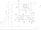
FIG. 1 is a schematic view of the overall cross-sectional structure of the present invention;
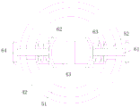
FIG. 2 is a schematic bottom sectional view of the circular ring of the present invention;
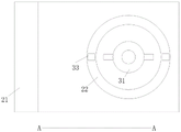
FIG. 3 is a schematic cross-sectional view taken along the line A-A of FIG. 1 according to the present invention;
fig. 4 is a schematic view of the cross-sectional structure of the electric telescopic rod of the present invention;
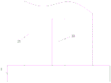
fig. 5 is a left side view structural diagram of the L-shaped supporting plate of the present invention.
In the figure: 1. a base;
2. a support mechanism; 21. an L-shaped support plate; 22. an annular groove; 23. a support bar;
3. a rotating mechanism; 31. a stepping motor; 32. a rotating plate; 33. rotating the rod;
4. a telescoping mechanism; 41. an electric telescopic rod; 42. a circular plate; 43. a chute;
5. an installation mechanism; 51. a circular ring; 52. mounting holes;
6. a clamping mechanism; 61. a movable rod; 62. an arc-shaped plate; 63. a rigid spring; 64. and (6) pulling the disc.
Detailed Description
The technical solutions in the embodiments of the present invention will be described clearly and completely with reference to the accompanying drawings in the embodiments of the present invention, and it is obvious that the described embodiments are only some embodiments of the present invention, not all embodiments. Based on the embodiments in the present invention, all other embodiments obtained by a person skilled in the art without creative work belong to the protection scope of the present invention.
Referring to fig. 1-5, the present invention provides a technical solution: the utility model provides a roll-like barreled wet piece of cloth bung tightening device, includes a base 1, and 1 one side upper end fixedly connected with supporting mechanism 2 of base, 2 lower surface fixedly connected with slewing mechanism 3 of supporting mechanism, 3 lower extreme fixedly connected with telescopic machanism 4 of slewing mechanism, 4 lower extreme fixedly connected with of telescopic machanism installation mechanism 5, the inside swing joint of installation mechanism 5 has a fixture 6.
Supporting mechanism 2 includes an L shape backup pad 21, L shape backup pad 21 fixed connection is at base 1 one side upper surface, an annular groove 22 has been seted up on L shape backup pad 21 top, one side fixedly connected with spinal branch vaulting pole 23 of annular groove 22 is kept away from to L shape backup pad 21, and bracing piece 23 lower extreme fixed connection base 1 upper surface, be favorable to conveniently supporting slewing mechanism 3 through L shape backup pad 21, telescopic machanism 4, installation mechanism 5 and fixture 6, make things convenient for two dwang 33 of sliding connection through annular groove 22, increase swivel plate 32 pivoted stability, conveniently increase L shape backup pad 21's steadiness through bracing piece 23.
Specifically, when the utility model is used, a wet tissue barrel to be processed is fixed on the base 1, then two pull discs 64 are pulled, the two pull discs 64 drive two movable rods 61 to move through two mounting holes 52, the two movable rods 61 synchronously pull the two arc plates 62 to move towards one side opposite to the two sliding grooves 43, at the moment, the two arc plates 62 can compress two rigid springs 63, then the barrel cover is placed in the middle of the circular ring 51, the two pull discs 64 are loosened, at the moment, the two arc plates 62 can be pushed to reset in the two sliding grooves 43 through the elastic action of the two rigid springs 63, at the moment, the two arc plates 62 can stably clamp the barrel cover, then the two electric telescopic rods 41 are started, the two electric telescopic rods 41 drive the circular plate 42 and the clamping mechanism 6 to synchronously descend, when the upper ends of the barrel cover and the wet tissue barrel abut against each other, the stepping motor 31 is started, the stepping motor 31 drives the rotating plate 32 to rotate, the rotating plate 32 drives the two rotating rods 33 to slide in the annular groove 22 to increase the rotating stability, and at the moment, the electric telescopic rod 41 drives the circular plate 42 and the barrel cover to continuously descend and install, so that the novel wet tissue barrel cover with different heights and the novel barrel covers with different specifications can be conveniently installed.
In the description of the present invention, it is to be understood that the terms "coaxial", "bottom", "one end", "top", "middle", "other end", "upper", "one side", "top", "inner", "front", "center", "both ends", and the like, indicate orientations or positional relationships based on the orientations or positional relationships shown in the drawings, and are only for convenience of description and simplicity of description, and do not indicate or imply that the device or element referred to must have a particular orientation, be constructed and operated in a particular orientation, and therefore, should not be construed as limiting the present invention.
Furthermore, the terms "first", "second", "third", "fourth" are used for descriptive purposes only and are not to be construed as indicating or implying a relative importance or implicitly indicating the number of technical features indicated, whereby the features defined as "first", "second", "third", "fourth" may explicitly or implicitly include at least one such feature.
In the present invention, unless otherwise expressly stated or limited, the terms "mounted," "disposed," "connected," "fixed," "screwed" and the like are to be construed broadly, e.g., as meaning fixedly connected, detachably connected, or integrally formed; can be mechanically or electrically connected; they may be directly connected or indirectly connected through an intermediate medium, and may be connected through the inside of two elements or in an interaction relationship between two elements, unless otherwise specifically defined, and the specific meaning of the above terms in the present invention will be understood by those skilled in the art according to specific situations.
Although embodiments of the present invention have been shown and described, it will be appreciated by those skilled in the art that changes, modifications, substitutions and alterations can be made in these embodiments without departing from the principles and spirit of the invention, the scope of which is defined in the appended claims and their equivalents.
Claims (6)
1. The utility model provides a roll-like barreled wet piece of cloth bung tightening device, a serial communication port, including a base (1), supporting mechanism (2) of fixedly connected with in base (1) one side upper end, slewing mechanism (3) of fixedly connected with under supporting mechanism (2), telescopic machanism (4) of slewing mechanism (3) lower extreme fixedly connected with, installation mechanism (5) of telescopic machanism (4) lower extreme fixed connection, installation mechanism (5) inside swing joint has a fixture (6).
2. The tightening device for the barrel cover of the roll-shaped barreled wet tissue as claimed in claim 1, is characterized in that: supporting mechanism (2) include an L shape backup pad (21), L shape backup pad (21) fixed connection is at base (1) one side upper surface, an annular groove (22) have been seted up on L shape backup pad (21) top, one side fixedly connected with bracing piece (23) of annular groove (22) are kept away from in L shape backup pad (21), just bracing piece (23) lower extreme fixed connection base (1) upper surface.
3. The tightening device for the barrel cover of the roll-shaped barreled wet tissue as claimed in claim 1, is characterized in that: slewing mechanism (3) include a step motor (31), step motor (31) fixed connection is at L shape backup pad (21) lower surface that is located ring channel (22) middle part, step motor (31) output end fixedly connected with rotor plate (32), rotor plate (32) upper surface both sides fixedly connected with two dwang (33) that are the symmetry and set up, and two dwang (33) upper end extends to in ring channel (22) and sliding connection is in ring channel (22).
4. The tightening device for the barrel cover of the roll-shaped barreled wet tissue as claimed in claim 1, is characterized in that: telescopic machanism (4) include two electric telescopic handle (41), two electric telescopic handle (41) are the symmetry and set up fixed connection in rotor plate (32) lower surface both sides, and two circular slab (42) of the common fixedly connected with of electric telescopic handle (41) lower extreme, a spout (43) has all been opened to circular slab (42) lower extreme both sides.
5. The tightening device for the barrel cover of the roll-shaped barreled wet tissue as claimed in claim 1, is characterized in that: the installation mechanism (5) comprises a circular ring (51), the circular ring (51) is fixedly connected to the lower surface of the circular plate (42), and two sides of the circular ring (51) are both provided with an installation hole (52) in a penetrating manner.
6. The tightening device for the barrel cover of the roll-shaped barreled wet tissue as claimed in claim 1, is characterized in that: fixture (6) includes two movable rod (61), two movable rod (61) sliding connection is in two mounting hole (52), and two movable rod (61) is arc (62), two of equal fixedly connected with in one side in opposite directions arc (62) in extending to two spout (43) and sliding connection in two spout (43), and two equal common rigid spring (63), two between arc (62) and circular ring (51) rigid spring (63) parcel is on two movable rod (61) pole walls, two equal fixedly connected with in one side of movable rod (61) draws dish (64) relatively.
Priority Applications (1)
| Application Number | Priority Date | Filing Date | Title |
|---|---|---|---|
| CN202022856324.9U CN213974575U (en) | 2020-12-03 | 2020-12-03 | Roll-shaped barreled wet tissue barrel cover screwing device |
Applications Claiming Priority (1)
| Application Number | Priority Date | Filing Date | Title |
|---|---|---|---|
| CN202022856324.9U CN213974575U (en) | 2020-12-03 | 2020-12-03 | Roll-shaped barreled wet tissue barrel cover screwing device |
Publications (1)
| Publication Number | Publication Date |
|---|---|
| CN213974575U true CN213974575U (en) | 2021-08-17 |
Family
ID=77240623
Family Applications (1)
| Application Number | Title | Priority Date | Filing Date |
|---|---|---|---|
| CN202022856324.9U Active CN213974575U (en) | 2020-12-03 | 2020-12-03 | Roll-shaped barreled wet tissue barrel cover screwing device |
Country Status (1)
| Country | Link |
|---|---|
| CN (1) | CN213974575U (en) |
Cited By (1)
| Publication number | Priority date | Publication date | Assignee | Title |
|---|---|---|---|---|
| CN114750994A (en) * | 2022-05-24 | 2022-07-15 | 铜陵鸿亿新材料科技有限公司 | Wet piece of cloth bung folding frock |
-
2020
- 2020-12-03 CN CN202022856324.9U patent/CN213974575U/en active Active
Cited By (2)
| Publication number | Priority date | Publication date | Assignee | Title |
|---|---|---|---|---|
| CN114750994A (en) * | 2022-05-24 | 2022-07-15 | 铜陵鸿亿新材料科技有限公司 | Wet piece of cloth bung folding frock |
| CN114750994B (en) * | 2022-05-24 | 2024-04-09 | 铜陵鸿亿新材料科技有限公司 | Wet towel barrel cover folding tool |
Similar Documents
| Publication | Publication Date | Title |
|---|---|---|
| CN213974575U (en) | Roll-shaped barreled wet tissue barrel cover screwing device | |
| CN210995469U (en) | Disinfection device for stethoscope | |
| CN209156670U (en) | A kind of biological cell culture reagent bottle cleaning device | |
| CN213832398U (en) | Cloth folding device is used in production of antibiotic wet piece of cloth in surface | |
| CN214858704U (en) | Department of neurology intensive care unit is with nursing device | |
| CN212702047U (en) | Test tube holder fixing device for hematology department | |
| CN210811523U (en) | Instrument rack for obstetrical operation | |
| CN212415911U (en) | Auxiliary table installation box for general surgery department work | |
| CN211568825U (en) | Medical equipment strorage device | |
| CN214129346U (en) | Oral cavity equipment operation panel convenient to height-adjusting just has categorised function of accomodating | |
| CN219397608U (en) | Multifunctional portable instrument bag | |
| CN215537493U (en) | General type fixing device is used in anesthesia screwed pipe and medical monitoring | |
| CN213466145U (en) | Internal disinfection device of can processing tank | |
| CN110680654B (en) | Multi-functional nursing shallow | |
| CN218792147U (en) | Sanitary cleaning cart for hotel | |
| CN218979212U (en) | Support frame for medical instrument | |
| CN217628287U (en) | Rose is essential oil purification device for cosmetics | |
| CN214400468U (en) | Novel culture dish clamping device | |
| CN211792562U (en) | Novel general type rotation type ONU equipment support | |
| CN214966661U (en) | Chamber mirror camera lens bracket | |
| CN216628105U (en) | Adjustable wine placing rack | |
| CN109533764A (en) | A kind of intelligent track movement system | |
| CN213190071U (en) | Nursing device for operating room | |
| CN214899895U (en) | Cable and patch cord fixing device for medical equipment | |
| CN215274184U (en) | Novel internal medicine nursing plate |
Legal Events
| Date | Code | Title | Description |
|---|---|---|---|
| GR01 | Patent grant | ||
| GR01 | Patent grant | ||
| TR01 | Transfer of patent right |
Effective date of registration: 20220815 Address after: 324022 No. 38, Linxi Road, Quzhou City, Zhejiang Province Patentee after: Zhejiang Bangliang nursing supplies Technology Co.,Ltd. Address before: 324000 floor 3, building 1, No. 29, Kaixuan West Road, Kecheng District, Quzhou City, Zhejiang Province Patentee before: ZHEJIANG BANGLIANG COMMODITY Co.,Ltd. |
|
| TR01 | Transfer of patent right |