CN213973128U - Adhesive label printing device - Google Patents
Adhesive label printing device Download PDFInfo
- Publication number
- CN213973128U CN213973128U CN202021981960.8U CN202021981960U CN213973128U CN 213973128 U CN213973128 U CN 213973128U CN 202021981960 U CN202021981960 U CN 202021981960U CN 213973128 U CN213973128 U CN 213973128U
- Authority
- CN
- China
- Prior art keywords
- fixedly connected
- bottom plate
- material roller
- driving device
- lifting frame
- Prior art date
- Legal status (The legal status is an assumption and is not a legal conclusion. Google has not performed a legal analysis and makes no representation as to the accuracy of the status listed.)
- Expired - Fee Related
Links
- 239000000853 adhesive Substances 0.000 title claims abstract description 13
- 230000001070 adhesive effect Effects 0.000 title claims abstract description 10
- 238000005520 cutting process Methods 0.000 claims abstract description 33
- 239000000463 material Substances 0.000 claims abstract description 32
- 230000005540 biological transmission Effects 0.000 claims abstract description 23
- 238000004140 cleaning Methods 0.000 claims abstract description 21
- 238000001035 drying Methods 0.000 claims abstract description 18
- 230000009467 reduction Effects 0.000 claims description 15
- 238000003825 pressing Methods 0.000 claims description 13
- 238000007599 discharging Methods 0.000 claims description 5
- 230000003028 elevating effect Effects 0.000 abstract description 4
- 238000000034 method Methods 0.000 description 5
- 208000032370 Secondary transmission Diseases 0.000 description 4
- 230000009471 action Effects 0.000 description 3
- 238000005516 engineering process Methods 0.000 description 3
- 230000008569 process Effects 0.000 description 3
- 230000004048 modification Effects 0.000 description 2
- 238000012986 modification Methods 0.000 description 2
- 241000219495 Betulaceae Species 0.000 description 1
- 230000001133 acceleration Effects 0.000 description 1
- 230000009286 beneficial effect Effects 0.000 description 1
- 239000000428 dust Substances 0.000 description 1
- 238000004043 dyeing Methods 0.000 description 1
- 230000006872 improvement Effects 0.000 description 1
- 239000012535 impurity Substances 0.000 description 1
- 238000005096 rolling process Methods 0.000 description 1
- 238000007711 solidification Methods 0.000 description 1
- 230000008023 solidification Effects 0.000 description 1
Images


Landscapes
- Auxiliary Devices For And Details Of Packaging Control (AREA)
Abstract
The utility model discloses a non-setting adhesive label printing device, including bottom plate, elevating gear, transmission, cleaning device, printing device, drying device and cutting device, bottom plate below fixedly connected with elevating gear, elevating gear includes first connecting block, second connecting block, crane, support base and a drive arrangement, transmission includes motor, reducing gear box, pivot, final drive wheel, follows drive wheel, drive belt, concentric shaft, workstation, does not print label material roller and has printed label material roller, the lower fixed surface of motor and bottom plate is connected, the output of motor and the left end fixed connection of reducing gear box, cleaning device, printing device, drying device and cutting device turn right from a left side and the lower fixed surface of workstation is connected, the utility model discloses collect clean, print, dry, Cut multi-functionally in an organic whole to have raising and lowering functions, make things convenient for getting of material to put.
Description
Technical Field
The utility model relates to a label printing technical field specifically is a non-setting adhesive label printing device.
Background
In present life, the non-setting adhesive label has more and more extensive application, along with the continuous development of label kind, the printing technology of non-setting adhesive label is also continuous development, the length of various printing technologies is absorbed to the label printing device, form relatively independent system gradually, current various label printing device functions are comparatively single, before printing the label, the label tape surface can fall impurity, influence printing quality, printing ink can't in time solidify after the completion of printing, printing and dyeing when leading to the rolling, and need later stage to cut, the process has been increased, a large amount of time has been wasted.
Therefore, a printing device for self-adhesive labels is needed to solve the existing problems.
SUMMERY OF THE UTILITY MODEL
An object of the utility model is to provide a non-setting adhesive label printing device to solve the problem that proposes among the above-mentioned background art.
In order to solve the technical problem, the utility model provides a following technical scheme: a non-setting adhesive label printing device, which comprises a bottom plate, a lifting device, a transmission device, a cleaning device, a printing device, a drying device and a cutting device, a lifting device is fixedly connected below the bottom plate and comprises a first connecting block, a second connecting block, a lifting frame, a supporting base and a first driving device, the first connecting block is fixedly connected with the lower surface of the bottom plate, the lifting frame is positioned below the first connecting block, the lifting frame is a scissor type, the upper end of the lifting frame is hinged with the first connecting block, the supporting bottom plate is positioned below the lifting frame, the upper surface of the supporting bottom plate is fixedly connected with the second connecting block, the lower end of the lifting frame is hinged with the second connecting block, the first driving device is positioned between the lifting frame and the supporting bottom plate, the first driving device is fixedly connected with the supporting bottom plate, and the output end of the first driving device is hinged with the lifting frame; the transmission device comprises a motor, a reduction box, a rotating shaft, a main driving wheel, a secondary driving wheel, a conveyor belt, a concentric shaft, a workbench, an unprinted label material roller and a printed label material roller, wherein the motor is fixedly connected with the lower surface of a bottom plate, the output end of the motor is fixedly connected with the input end of the reduction box, the reduction box is fixedly connected with the lower surface of the right end of the bottom plate, the rotating shaft is fixedly arranged at the output end of the reduction box, the main driving wheel is fixedly arranged at the front end of the rotating shaft, the main driving wheel is in transmission connection with the secondary driving wheel through the conveyor belt, the printed label material roller is arranged at the right end of the upper surface of the bottom plate through a bracket, the concentric shaft of the printed label material roller is provided with a secondary driving wheel, the secondary driving wheel is fixedly connected with the concentric shaft, the left end of the upper surface of the bottom plate is provided with the unprinted label material roller through the bracket, the upper surface of the bottom plate is provided with a workbench, the lower surface of the workbench is fixedly connected with the upper surface of the bottom plate, a printing label tape is wound on the non-printing label material roller, the feeding end of the printing label tape extends and covers the upper surface of the workbench, and the discharging end of the printing label tape is connected with the periphery of the printing label material roller; cleaning device, printing device, drying device and cutting device turn right from a left side and the lower fixed surface of workstation is connected, can freely adjust this printing device's height, conveniently gets and puts the label area.
Further, cleaning device includes bracing piece, location roof, first elastic component, limiting plate, adjusting nut and clean brush, the lower extreme of bracing piece and the last fixed surface of workstation are connected, the upper end fixed connection of location roof (22) and bracing piece (19), the limiting plate cover is located on the bracing piece, the bracing piece is the threaded rod, the pot head is equipped with adjusting nut under the bracing piece, adjusting nut is located the limiting plate below, the bottom fixed connection of clean brush and limiting plate, first elastic component cover is established on the bracing piece, is located between location roof and the limiting plate, can clean the label area, prevents that debris or dust from falling on the print tape surface.
Further, drying device includes first casing, ultraviolet lamp and air-blower, the last fixed surface of first casing and workstation is connected, the inside of first casing is equipped with ultraviolet lamp, the top inner wall fixed connection of ultraviolet lamp and first casing, air-blower and first casing top outer wall fixed connection, the air-blower left end is equipped with the air intake, the air-blower right-hand member is equipped with the air outlet, and the air-blower has increased the inside circulation of air of drying device, and the curing speed of printing ink has been practiced thrift to the speed of acceleration.
Further, the cutting device comprises a second shell, a cutter sleeve, a second driving device and a cutting blade, the second shell is fixedly connected with the upper surface of the workbench, the cutter sleeve is positioned in the second shell, the cutter sleeve is fixedly connected with the inner wall of the top end of the second shell, the second driving device, a pressing plate and a second elastic piece are arranged in the cutter sleeve, the inner wall of the top end of the second driving device is fixedly connected with the inner wall of the top end of the second shell and is positioned in the cutter sleeve, the pressing plate is positioned below the second driving device, the bottom of the pressing plate is fixedly connected with the cutting blade, the cutting blade penetrates through the bottom end of the cutter sleeve, the second elastic piece is positioned between the bottom end of the cutter sleeve and the pressing plate, one end of the second elastic piece is fixedly connected with the bottom of the pressing plate, the other end of the second elastic piece is fixedly connected with the inner wall of the bottom end of the cutter sleeve, and the height of the cutting blade can be freely adjusted, accommodating different tags.
Further, the first driving device is a hydraulic cylinder with a model of HSG-40 × 25 × 100, and the manufacturer is star Rui hydraulic technology ltd.
Further, the second driving device is a pneumatic cylinder with model number SC50 × 25, and the manufacturer is international group of alder.
Further, the motor model is YE2, and the manufacturer is Fang Li Jiang Bingquan GmbH.
Further, the reduction gearbox is NMRV 025, and the manufacturer is Ruijin mechanical factory.
Further, the printing apparatus model is PRO 540S, and the manufacturer is canon limited.
Compared with the prior art, the utility model discloses the beneficial effect who reaches is: the utility model discloses collect printing, cleanness, drying, cutting in an organic whole, practiced thrift the time cost of printing label greatly, drying device has increased the air-blower, has accelerateed the circulation of air, is that solidification speed improves greatly, and cutting device's cutting blade adopts adjustable mode, is fit for the label of multiple different thickness, and this printing device adopts elevating gear, can freely height-adjusting, conveniently gets and puts the material.
Drawings
The accompanying drawings are included to provide a further understanding of the invention, and are incorporated in and constitute a part of this specification, illustrate embodiments of the invention, and together with the description serve to explain the invention and not to limit the invention. In the drawings:
FIG. 1 is a schematic structural view of a printing device for self-adhesive labels of the present invention;
FIG. 2 is a schematic view of the bottom structure of a printing device for self-adhesive labels of the present invention;
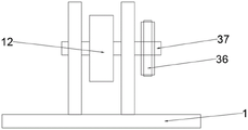
FIG. 3 is a schematic view of the structure of the printed label material roller of the present invention;
FIG. 4 is a schematic view of the cleaning device of the present invention;
FIG. 5 is a schematic structural view of the drying device of the present invention;
FIG. 6 is a schematic view of the cutting device of the present invention;
in the figure: 1, a bottom plate; 2, a workbench; 3, lifting the rack; 4, a first fixed block; 5, a second fixed block; 6 supporting the base; 7 a first drive device; 8, a motor; 9, a reduction gearbox; 10, conveying a belt; 11 a roll of unprinted label stock; 12 a roll of printed label stock; 13 printing the label tape; 14 cleaning the brush; 15 a printing device; 16 a drying device; 17 a cutting device; 18 limiting plates; 19 supporting rods; 20 a first elastic member; 21 adjusting the nut; 22 positioning the top plate; 23 a first housing; 24 ultraviolet lamps; 25 a blower; 26 air inlets; 27 air outlet; 28 a second housing; 29 a cutter sleeve; 30 a second drive device; 31, pressing a plate; 32 a second elastic member; 33 a cutting blade; 34 a rotating shaft; 35 a main rotating wheel; 36 from the rotating wheel; 37 concentric with the shaft; 38 support frame.
Detailed Description
The technical solutions in the embodiments of the present invention will be described clearly and completely with reference to the accompanying drawings in the embodiments of the present invention, and it is obvious that the described embodiments are only some embodiments of the present invention, not all embodiments. Based on the embodiments in the present invention, all other embodiments obtained by a person skilled in the art without creative work belong to the protection scope of the present invention.
Referring to fig. 1-6, the present invention provides a technical solution:
a non-setting adhesive label printing device comprises a bottom plate 1, a lifting device, a transmission device, a cleaning device, a printing device 15, a drying device 16 and a cutting device 17, wherein the lifting device is fixedly connected below the bottom plate 1, the lifting device comprises a first fixed block 4, a second fixed block 5, a lifting frame 3, a supporting base 6 and a first driving device 7, the first fixed block 4 is fixedly connected with the lower surface of the bottom plate 1, the lifting frame 3 is positioned below the first fixed block 4, the lifting frame 3 is a scissor type fork, the upper end of the lifting frame 3 is hinged with the first fixed block 4, the supporting base 6 is positioned below the lifting frame 3, the upper surface of the supporting base 6 is fixedly connected with the second fixed block 5, the lower end of the lifting frame 3 is hinged with the second fixed block 5, the first driving device 7 is positioned between the lifting frame 3 and the supporting bottom plate, the first driving device 7 is fixedly connected with the supporting bottom plate, the output end of the first driving device 7 is hinged with the lifting frame 3, the first driving device 7 is a hydraulic cylinder with the model number of HSG-40 × 25 × 100; the transmission device comprises a motor 8, a reduction box 9, a rotating shaft 34, a main transmission wheel 35, a secondary transmission wheel 36, a conveyor belt 10, a concentric shaft 37, a workbench 2, an unprinted label material roller 11 and a printed label material roller 12, wherein the model of the motor is YE2, the motor 8 is fixedly connected with the lower surface of the bottom plate 1, the output end of the motor 8 is fixedly connected with the input end of the reduction box 9, the model of the reduction box is NMRV 025, the reduction box 9 is fixedly connected with the lower surface of the right end of the bottom plate 1, the rotating shaft 34 is fixedly arranged at the output end of the reduction box 9, the main transmission wheel 35 is fixedly arranged at the front end of the rotating shaft 34, the main transmission wheel 35 is in transmission connection with the secondary transmission wheel 36 through the conveyor belt 10, the printed label material roller 12 is erected at the right end of the upper surface of the bottom plate 1 through a bracket 38, the concentric shaft 37 of the printed label material roller 12 is provided with the secondary transmission wheel 36, the secondary transmission wheel 35 is fixedly connected with the concentric shaft 37, the left end of the upper surface of the bottom plate 1 is provided with an unprinted label material roller 11 through a bracket 38, the upper surface of the bottom plate 1 is provided with a workbench 2, the lower surface of the workbench 2 is fixedly connected with the upper surface of the bottom plate 1, a printed label tape 13 is wound on the unprinted label material roller 11, the feeding end of the printed label tape 13 extends and covers the upper surface of the workbench 2, and the discharging end of the printed label tape 13 is connected with the periphery of a printed label material roller 12; the cleaning device, the printing device 15, the drying device 16 and the cutting device 17 are fixedly connected with the lower surface of the workbench 2 from left to right.
Starting the first driving device 7, the output end of the first driving device 7 contracts to drive the lifting frame 3 to contract downwards, the bottom plate 1 descends, the printing label tape is wound on the non-printing label material roller 11, the feeding end of the printing label tape 13 extends and covers the upper surface of the workbench 2, the discharging end of the printing label tape 13 is connected with the periphery of the printing label material roller 12, then the adjusting nut 21 is adjusted to move the limiting plate 18, the cleaning brush contacts the printing label tape 13, one end of the spring abuts against the positioning top plate 22, the other end of the spring abuts against the limiting plate 18 to fix the cleaning brush 14, then the ultraviolet lamp 24 of the drying device 16 is opened, the air blower 25 is started, then the second driving device 30 is started to make the output end of the second driving device 30 move downwards, the output end abuts against the upper surface of the pressing plate 31 to drive the cutting blade 33 to move downwards, make cutting blade 33 most advanced contact print meter label area 13, the spring is located the clamp plate 31 below, make cutting blade 33 fixed, start printing device 15 after that, then start first drive arrangement 7, the output extension of first drive arrangement 7, it rises upwards to drive crane 3, bottom plate 1 rises, start motor 8 at last, the input of reducing gear box 9 is connected to the output of motor 8, adjust transmission speed, the output of reducing gear box 9 drives the rotation of main drive wheel 35, main drive wheel 35 makes the transmission of follow drive wheel 36 through conveyer belt 10, it rotates to drive from drive wheel 36 and has printed label material roller 12, it moves on workstation 2 to drive print label area 13, printing device begins work.
Cleaning device includes bracing piece 19, location roof 22, first elastic component 20, limiting plate 18, adjusting nut 21 and cleaning brush 14, the lower extreme of bracing piece 19 and the last fixed surface of workstation 2 are connected, the upper end fixed connection of location roof 22 and bracing piece 19, limiting plate 18 overlaps locates on bracing piece 19, bracing piece 19 is the threaded rod, 19 pot heads of bracing piece are equipped with adjusting nut 21, adjusting nut 21 is located limiting plate 18 below, the bottom fixed connection of cleaning brush 14 and limiting plate 18, first elastic component 20 covers is established on bracing piece 19, be located between location roof 22 and the limiting plate 18, first elastic component 20 is the spring.
The cutting device 17 comprises a second shell 28, a cutter sleeve 29, a second driving device 30 and a cutting blade 33, the second shell 28 is fixedly connected with the upper surface of the workbench 2, the cutter sleeve 29 is positioned in the second shell 28, the cutter sleeve 29 is fixedly connected with the inner wall of the top end of the second shell 28, the second driving device 30, a pressure plate 31 and a second elastic member 32 are arranged in the cutter sleeve 29, the second driving device 30 is fixedly connected with the inner wall of the top end of the second shell 28 and positioned in the cutter sleeve 29, the pressure plate 31 is positioned below the second driving device 30, the second driving device is a pneumatic cylinder, the model is SC50, the bottom of the pressure plate 31 is fixedly connected with the cutting blade 33, the cutting blade 33 penetrates through the bottom end of the cutter sleeve 29, the second elastic member 32 is positioned between the bottom end of the cutter sleeve 29 and the pressure plate 31, one end of the second elastic member 32 is fixedly connected with the bottom end of the pressure plate 31, the other end of the second elastic member 32 is fixedly connected with the bottom end of the inner wall of the cutter sleeve 29, the second elastic member 32 is a spring.
The utility model discloses a theory of operation: when the device is used, the lifting device is adjusted firstly, the first driving device 7 is started, the output end of the first driving device 7 contracts to drive the lifting frame 3 to contract downwards, the bottom plate 1 descends, the label printing tape is wound on the non-printed label material roller 11, the feeding end of the label printing tape 13 extends to cover the upper surface of the workbench 2, the discharging end of the label printing tape 13 is connected with the periphery of the printed label material roller 12, the adjusting nut 21 is adjusted to enable the limiting plate 18 to move, the cleaning brush is contacted with the label printing tape 13, one end of the first elastic part 20 is abutted against the positioning top plate 22, the other end of the first elastic part is abutted against the limiting plate 18 to enable the cleaning brush 14 to be fixed, the ultraviolet lamp 24 of the drying device 16 is opened, the air blower 25 is started, the second driving device 30 is started, the output end of the second driving device 30 moves downwards, the output end of the second driving device 30 is abutted against the upper surface of the pressing plate 31 to drive the cutting blade 33 to move downwards, make cutting blade 33 pointed end contact print meter label area 13, second elastic component 32 is located clamp plate 31 below, make cutting blade 33 fixed, start printing device 15 after that, then start first drive arrangement 7, the output extension of first drive arrangement 7, drive crane 3 and rise upwards, bottom plate 1 rises, last starting motor 8, the input of reducing gear box 9 is connected to the output of motor 8, adjust transmission speed, the output of reducing gear box 9 drives the rotation of main drive wheel 35, main drive wheel 35 makes the transmission of follow drive wheel 36 through conveyer belt 10, it rotates to drive from drive wheel 36 and has printed label material roller 12, drive and print label area 13 and move on workstation 2, printing device begins work.
It is noted that, herein, relational terms such as first and second, and the like may be used solely to distinguish one entity or action from another entity or action without necessarily requiring or implying any actual such relationship or order between such entities or actions. Also, the terms "comprises," "comprising," or any other variation thereof, are intended to cover a non-exclusive inclusion, such that a process, method, article, or apparatus that comprises a list of elements does not include only those elements but may include other elements not expressly listed or inherent to such process, method, article, or apparatus.
Finally, it should be noted that: although the present invention has been described in detail with reference to the foregoing embodiments, it will be apparent to those skilled in the art that modifications may be made to the embodiments described in the foregoing embodiments, or equivalents may be substituted for elements thereof. Any modification, equivalent replacement, or improvement made within the spirit and principle of the present invention should be included in the protection scope of the present invention.
Claims (6)
1. The utility model provides a non-setting adhesive label printing device which characterized in that: comprises a bottom plate (1), a lifting device, a transmission device, a cleaning device, a printing device (15), a drying device (16) and a cutting device (17), wherein the lifting device is fixedly connected below the bottom plate (1), the lifting device comprises a first fixed block (4), a second fixed block (5), a lifting frame (3), a supporting base (6) and a first driving device (7), the first fixed block (4) is fixedly connected with the lower surface of the bottom plate (1), the lifting frame (3) is positioned below the first fixed block (4), the lifting frame (3) is a scissor type, the upper end of the lifting frame (3) is hinged with the first fixed block (4), the supporting base (6) is positioned below the lifting frame (3), the upper surface of the supporting base (6) is fixedly connected with the second fixed block (5), the lower end of the lifting frame (3) is hinged with the second fixed block (5), the first driving device (7) is positioned between the lifting frame (3) and the supporting bottom plate, the first driving device (7) is fixedly connected with the supporting bottom plate, and the output end of the first driving device (7) is hinged with the lifting frame (3); the transmission device comprises a motor (8), a reduction box (9), a rotating shaft (34), a main transmission wheel (35), a driven transmission wheel (36), a conveyor belt (10), a concentric shaft (37), a workbench (2), a non-printed label material roller (11) and a printed label material roller (12), wherein the motor (8) is fixedly connected with the lower surface of the bottom plate (1), the output end of the motor (8) is fixedly connected with the input end of the reduction box (9), the reduction box (9) is fixedly connected with the lower surface of the right end of the bottom plate (1), the rotating shaft (34) is fixedly arranged at the output end of the reduction box (9), the main transmission wheel (35) is fixedly arranged at the front end of the rotating shaft (34), the main transmission wheel (35) is in transmission connection with the driven transmission wheel (36) through the conveyor belt (10), the printed label material roller (12) is erected at the right end of the upper surface of the bottom plate (1) through a support (38), a driven wheel (36) is arranged on a concentric shaft (37) of the printed label material roller (12), the driven wheel (36) is fixedly connected with the concentric shaft (37), the left end of the upper surface of the bottom plate (1) is provided with a non-printed label material roller (11) through a support (38), the upper surface of the bottom plate (1) is provided with a workbench (2), the lower surface of the workbench (2) is fixedly connected with the upper surface of the bottom plate (1), a printed label tape (13) is wound on the non-printed label material roller (11), the feeding end of the printed label tape (13) extends and covers the upper surface of the workbench (2), and the discharging end of the printed label tape (13) is connected with the periphery of the printed label material roller (12); the cleaning device, the printing device (15), the drying device (16) and the cutting device (17) are fixedly connected with the lower surface of the workbench (2) from left to right.
2. The sticker label printing apparatus as recited in claim 1, wherein: cleaning device includes bracing piece (19), location roof (22), first elastic component (20), limiting plate (18), adjusting nut (21) and cleaning brush (14), the lower extreme of bracing piece (19) and the last fixed surface of workstation (2) are connected, the upper end fixed connection of location roof (22) and bracing piece (19), limiting plate (18) cover is located on bracing piece (19), bracing piece (19) are the threaded rod, the pot head is equipped with adjusting nut (21) under bracing piece (19), adjusting nut (21) is located limiting plate (18) below, the bottom fixed connection of cleaning brush (14) and limiting plate (18), first elastic component (20) cover is established on bracing piece (19), is located between location roof (22) and limiting plate (18).
3. The sticker label printing apparatus as recited in claim 1, wherein: drying device (16) includes first casing (23), ultraviolet lamp (24) and air-blower (25), the last fixed surface of first casing (23) and workstation (2) is connected, the inside of first casing (23) is equipped with ultraviolet lamp (24), the top inner wall fixed connection of ultraviolet lamp (24) and first casing (23), air-blower (25) and first casing (23) top outer wall fixed connection, air-blower (25) left end is equipped with air intake (26), air-blower (25) right-hand member is equipped with air outlet (27).
4. The sticker label printing apparatus as recited in claim 1, wherein: the cutting device (17) comprises a second shell (28), a cutter sleeve (29), a second driving device (30) and a cutting blade (33), the second shell (28) is fixedly connected with the upper surface of the workbench (2), the cutter sleeve (29) is positioned in the second shell (28), the cutter sleeve (29) is fixedly connected with the inner wall of the top end of the second shell (28), the cutter sleeve (29) is internally provided with the second driving device (30), a pressing plate (31) and a second elastic piece (32), the second driving device (30) is fixedly connected with the inner wall of the top end of the second shell (28) and positioned in the cutter sleeve (29), the pressing plate (31) is positioned below the second driving device (30), the bottom of the pressing plate (31) is fixedly connected with the cutting blade (33), the cutting blade (33) penetrates through the bottom end of the cutter sleeve (29), and the second elastic piece (32) is positioned between the bottom end of the cutter sleeve (29) and the pressing plate (31), one end of the second elastic piece (32) is fixedly connected with the bottom of the pressing plate (31), and the other end of the second elastic piece (32) is fixedly connected with the inner wall of the bottom end of the cutter sleeve (29).
5. The sticker label printing apparatus as recited in claim 1, wherein: the first driving device (7) is a hydraulic cylinder.
6. The sticker label printing apparatus according to claim 4, wherein: the second driving means (30) is a pneumatic cylinder.
Priority Applications (1)
| Application Number | Priority Date | Filing Date | Title |
|---|---|---|---|
| CN202021981960.8U CN213973128U (en) | 2020-09-11 | 2020-09-11 | Adhesive label printing device |
Applications Claiming Priority (1)
| Application Number | Priority Date | Filing Date | Title |
|---|---|---|---|
| CN202021981960.8U CN213973128U (en) | 2020-09-11 | 2020-09-11 | Adhesive label printing device |
Publications (1)
| Publication Number | Publication Date |
|---|---|
| CN213973128U true CN213973128U (en) | 2021-08-17 |
Family
ID=77253488
Family Applications (1)
| Application Number | Title | Priority Date | Filing Date |
|---|---|---|---|
| CN202021981960.8U Expired - Fee Related CN213973128U (en) | 2020-09-11 | 2020-09-11 | Adhesive label printing device |
Country Status (1)
| Country | Link |
|---|---|
| CN (1) | CN213973128U (en) |
Cited By (1)
| Publication number | Priority date | Publication date | Assignee | Title |
|---|---|---|---|---|
| CN113619273A (en) * | 2021-09-03 | 2021-11-09 | 江苏鸿皓包装有限公司 | Printing device for plastic packaging bag production |
-
2020
- 2020-09-11 CN CN202021981960.8U patent/CN213973128U/en not_active Expired - Fee Related
Cited By (1)
| Publication number | Priority date | Publication date | Assignee | Title |
|---|---|---|---|---|
| CN113619273A (en) * | 2021-09-03 | 2021-11-09 | 江苏鸿皓包装有限公司 | Printing device for plastic packaging bag production |
Similar Documents
| Publication | Publication Date | Title |
|---|---|---|
| CN216734942U (en) | Laminating device is used in touch-sensitive screen production | |
| CN213973128U (en) | Adhesive label printing device | |
| CN113211964A (en) | Hub machining rear end comprehensive equipment | |
| CN114248535A (en) | Automatic silk screen printing coating film former | |
| CN117303062A (en) | Full-automatic film winding machine | |
| CN216183729U (en) | Cigarette case facing slip lithography apparatus | |
| CN210415898U (en) | Novel digital monochrome printing device | |
| CN216579794U (en) | Thermal label printer without backing paper | |
| CN210970355U (en) | Cooling and cleaning device of printing machine | |
| CN221250186U (en) | Self-adhesive label printing device | |
| CN221292646U (en) | Disconnect-type oiling mechanism | |
| CN110802940A (en) | Be used for trade propaganda single page printing and integrative equipment of drying | |
| CN221586035U (en) | Shearing device for printing machine | |
| CN220482857U (en) | Printing static-removing device | |
| CN213501370U (en) | High-efficiency screen printing device for glass plate | |
| CN213704906U (en) | Adjustable printed matter overturning and paper aligning device | |
| CN213649104U (en) | Wrapping bag printing machine with stoving effect | |
| CN219173874U (en) | Printing stripping mechanism for glue surface of printed matter | |
| CN219486881U (en) | Corrugated carton printing device | |
| CN218749891U (en) | Printer is used in label production | |
| CN221017553U (en) | Labeling device for loudspeaker production | |
| CN221757182U (en) | Clothing tablet marking machine | |
| CN210418527U (en) | Automatic material receiving and positioning device of large-size printing mechanism | |
| CN212402440U (en) | Automatic resistor disc printing pick-and-place machine | |
| CN221067558U (en) | Code spraying equipment for printing of printed matter |
Legal Events
| Date | Code | Title | Description |
|---|---|---|---|
| GR01 | Patent grant | ||
| GR01 | Patent grant | ||
| CF01 | Termination of patent right due to non-payment of annual fee |
Granted publication date: 20210817 |
|
| CF01 | Termination of patent right due to non-payment of annual fee |