CN213968689U - High-precision bending machine - Google Patents
High-precision bending machine Download PDFInfo
- Publication number
- CN213968689U CN213968689U CN202022782388.9U CN202022782388U CN213968689U CN 213968689 U CN213968689 U CN 213968689U CN 202022782388 U CN202022782388 U CN 202022782388U CN 213968689 U CN213968689 U CN 213968689U
- Authority
- CN
- China
- Prior art keywords
- adjusting screw
- plate
- positioning
- frame
- slide rail
- Prior art date
- Legal status (The legal status is an assumption and is not a legal conclusion. Google has not performed a legal analysis and makes no representation as to the accuracy of the status listed.)
- Active
Links
Images


Abstract
The utility model relates to a high-precision bending machine, which comprises a machine base and a die, wherein the machine base is provided with a first positioning device and a second positioning device, the first positioning device and the second positioning device are respectively arranged at two sides of the die in the length direction, the first positioning device comprises a plurality of supporting tables and a positioning table arranged at the upper end of the supporting tables, the supporting tables are distributed along the length direction of the die, the upper end of the positioning table is provided with a positioning plate, the second positioning device comprises a supporting frame and a supporting plate arranged at the upper end of the supporting frame, the positioning table can support plates, the positioning plate can position the plates, a pressing device can clamp the plates, the stability of the plates during processing can be effectively improved, thereby promote the machining precision of bender, first positioner and second positioner are fixed a position and are supported panel jointly, have further promoted the stability that panel was processed man-hour.
Description
Technical Field
The utility model belongs to the technical field of the bender technique and specifically relates to a high accuracy bender is related to.
Background
The bending machine is a machine capable of bending a thin plate, and when the bending machine bends the thin plate, a first positioning device is needed to position the thin plate so as to ensure the working precision of the bending machine.
Among the prior art, utility model patent that publication number is CN206215791U specifically discloses a bender first positioner, including workstation, mould, first positioner, go up mould, knife rest, fastening bolt, support, briquetting, spring, slider, tightly decide bolt, lock nut, compress tightly the pole, measure the slider, measure the screw rod, measure support, panel. The mould is installed on the workstation, it installs on the knife rest to go up the mould, the spout of mould is arranged in to the support, and fix on the mould through fastening bolt, the T-slot of support is arranged in to the slider, and fix on the support through fastening bolt, the compaction hole of slider front end is arranged in to the compression bar, the lower extreme at the compression bar is fixed in the briquetting installation, the spring is arranged in between briquetting and the slider, lock nut installs on the compression bar, measure the support and pass through fixing bolt and install on the support, measure the slider and arrange in the spout of measuring the support, measure the screw rod and arrange in the screw rod hole of measuring the support, panel is arranged in on the mould. The support and the measuring slide block can be used for positioning the plate placed on the die, and the plate is compressed by the compression rod and the compression block, so that the plate can be fixed on the die, and the purpose of positioning the plate is achieved.
However, in the above scheme, the plate is directly placed on the die, and when the plate is large in size, the die is not easy to provide sufficient supporting force for the plate due to the limited contact area between the plate and the die, so that the plate is easy to shift in the processing process, and the processing precision of the bending machine is easily influenced.
SUMMERY OF THE UTILITY MODEL
Not enough to prior art exists, the utility model provides a high accuracy bender can provide sufficient holding power to panel, makes panel be difficult for taking place the skew in the course of working to promote the machining precision of bender.
The above object of the present invention is achieved by the following technical solutions:
a high-precision bending machine comprises a machine base and a die arranged on the machine base, wherein a first positioning device and a second positioning device are arranged on the machine base, the first positioning device and the second positioning device are respectively arranged on two sides of the die in the length direction, and the first positioning device comprises a plurality of supporting tables connected with the machine base and positioning tables arranged at the upper ends of the supporting tables;
the supporting tables are distributed along the length direction of the mold, and a positioning plate is arranged on one side, away from the mold, of the upper end of each positioning table and is arranged along the length direction of the mold;
the second positioning device comprises a support frame connected with the base and a support plate horizontally arranged at the upper end of the support frame.
Through adopting the above technical scheme, first positioner and second positioner set up both sides on mould length direction respectively, location platform and backup pad can provide the holding power to panel respectively, thereby promote the stability of panel, the locating plate can fix a position panel, guarantee the accuracy nature of panel position, thereby guarantee the machining precision of panel, a plurality of support platforms distribute along mould length direction, thereby make the location platform can support the different positions of panel, make panel be difficult for taking place the skew in the course of working, promote the stability of panel in the course of working, thereby promote the machining precision of panel.
The present invention may be further configured in a preferred embodiment as: a connecting frame is arranged on one side, away from the die, of the positioning table, the upper end of the connecting frame extends to the position above the positioning table, and a pressing device is arranged above the positioning table;
the compressing device comprises a compressing block and a vertically arranged air cylinder, wherein a cylinder body of the air cylinder is arranged above the piston rod and fixedly connected with the connecting frame, and the upper end of the compressing block is hinged with the end part of the piston rod of the air cylinder.
Through adopting above-mentioned technical scheme, the cylinder can drive the compact heap and move in vertical direction to can provide sufficient packing force to panel, promote panel stability of processing man-hour, the compact heap is articulated with cylinder piston rod, can promote the flexibility of compact heap, can make the compact heap inseparabler with the laminating of panel terminal surface, promote the stability of panel.
The present invention may be further configured in a preferred embodiment as: be provided with first slide rail between frame and the brace table, first slide rail sets up along mould length direction, and is a plurality of all set up the first spout of sliding with first slide rail and being connected on the brace table, still be provided with a plurality of drive arrangement that are used for driving the brace table and remove on the frame.
Through adopting above-mentioned technical scheme, drive arrangement drives a supporting bench and removes, makes a supporting bench can remove to the optional position on first slide rail, adds man-hour when the different positions of needs to panel to can fix a position the different positions of panel, promote the flexibility of first positioner work, can guarantee simultaneously that first positioner can effectually provide support and location to panel.
The present invention may be further configured in a preferred embodiment as: it is a plurality of drive arrangement all include with frame fixed connection's motor and with the coaxial fixed connection's of motor output ball, it is a plurality of ball all with first slide rail parallel arrangement, it is a plurality of brace table respectively with a plurality of ball threaded connection.
Through adopting above-mentioned technical scheme, first motor drives ball and rotates to can drive a supporting bench and remove on the slide rail, utilize screw rod drive's accuracy nature, guarantee the accuracy nature of a supporting bench position, can promote first positioner's degree of automation simultaneously, promote work efficiency.
The present invention may be further configured in a preferred embodiment as: a first groove is formed in the positioning table, the first groove is arranged in the direction perpendicular to the end face of the positioning plate, and a first sliding block connected with the first groove in a sliding mode is arranged at the lower end of the positioning table;
be provided with first adjusting screw between location platform and the locating plate, first adjusting screw and first recess parallel arrangement, set up the storage tank that is used for placing first adjusting screw on the location platform, first adjusting screw's both ends all are rotated with the location platform and are connected, first adjusting screw and locating plate threaded connection.
Through adopting above-mentioned technical scheme, through rotating first adjusting screw, can drive the locating plate and remove on the location bench to can control the distance between locating plate and the mould, make the locating plate can provide support and location to the panel of equidimension not, guarantee the stability of panel, promoted first positioner's application scope simultaneously.
The present invention may be further configured in a preferred embodiment as: a first guide rod is vertically arranged at the lower end of the positioning table, and a first guide groove connected with the first guide rod in a sliding manner is formed in the supporting table;
the supporting table is vertically provided with a second adjusting screw rod, the upper end and the lower end of the second adjusting screw rod are rotatably connected with the supporting table, and a first guide block in threaded connection with the second adjusting screw rod is fixedly connected to the first guide rod.
Through adopting above-mentioned technical scheme, through rotating second adjusting screw for first guide bar can slide in first guide way, thereby drives the location platform and reciprocates, can adjust the height of location platform, makes the location platform can adapt to the location requirement of different panel processing, promotes first positioner's application scope.
The present invention may be further configured in a preferred embodiment as: the die is characterized in that a second sliding rail is arranged between the support frame and the base, the second sliding rail is arranged along the length direction of the die and is arranged in parallel with the die, the second sliding rail is fixedly connected with the base through a connecting rod, and a second sliding groove connected with the second sliding rail in a sliding manner is formed in the support frame.
Through adopting above-mentioned technical scheme, the backup pad can support panel, can promote the stability in the panel course of working, and the support frame can slide on the second slide rail to can adjust the position of backup pad, the second positioner of being convenient for can effectively cooperate first positioner work, make that first positioner and second positioner can be better support panel.
The present invention may be further configured in a preferred embodiment as: the vertical second guide bar that is provided with of backup pad lower extreme, set up on the support frame and slide the second guide way of being connected with the guide bar, the vertical third adjusting screw that is provided with on the support frame, third adjusting screw's upper end and lower extreme all rotate with the support frame to be connected, be provided with the second guide block with third adjusting screw threaded connection on the second guide bar.
Through adopting above-mentioned technical scheme, through rotating adjusting screw, can make the second guide bar slide from top to bottom in the second guide way to can adjust the height of backup pad, make second positioner can adapt to the location requirement of different panel processing, promote second positioner's application scope.
The present invention may be further configured in a preferred embodiment as: the upper end of the supporting plate is provided with a butt plate, the butt plate is arranged along the length direction of the die, the upper end of the supporting plate is provided with a second groove, the second groove is arranged along the direction vertical to the end face of the butt plate, and the lower end of the butt plate is provided with a second sliding block connected with the second groove in a sliding manner;
the supporting plate is characterized in that a fourth adjusting screw is arranged between the supporting plate and the butt plate, a placing groove used for placing the fourth adjusting screw is formed in the supporting plate, the axis of the fourth adjusting screw is perpendicular to the end face of the butt plate, two ends of the fourth adjusting screw are rotatably connected with the supporting plate, and the butt plate is in threaded connection with the fourth adjusting screw.
Through adopting above-mentioned technical scheme, the butt board can support and hold panel, can promote panel stability in the backup pad effectively to can promote the second positioner to the supporting effect of panel, promote the stability of panel, simultaneously, through rotating fourth adjusting screw, can make the butt board remove along the second recess, make the butt board can support and hold the not panel of equidimension, promote second positioner's application scope.
To sum up, the utility model discloses a following at least one useful technological effect:
1. the positioning table can support the plate, the positioning plate can position the plate, and the pressing device can press the plate, so that the stability of the plate during processing can be effectively improved, and the processing precision of the bending machine is improved;
2. the second positioning device can support and position the plate, and the first positioning device and the second positioning device can jointly position and support the plate, so that the stability of the plate during processing is further improved;
3. the height positions of the first positioning device and the second positioning device can be adjusted, the positioning requirements of different plates can be met, and the application range of the bending machine can be widened while the machining precision is improved.
Drawings
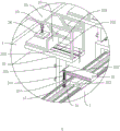
FIG. 1 is a schematic diagram of a bending machine configuration;
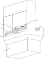
FIG. 2 is a view showing the structure of a first positioning device;
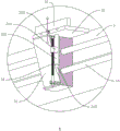
FIG. 3 is an enlarged partial schematic view of portion A of FIG. 2;
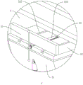
FIG. 4 is a view showing the connection relationship between the connection rack and the second slide rail;
FIG. 5 is an enlarged partial schematic view of portion B of FIG. 4;
FIG. 6 is a view showing the connection relationship between the abutting plate and the supporting plate;
fig. 7 is a partially enlarged schematic view of a portion C in fig. 6.
In the figure, 1, a machine base; 11. a first slide rail; 12. a motor; 13. a ball screw; 14. a second slide rail; 2. a first positioning device; 21. a support table; 211. a second adjusting screw; 212. a first guide groove; 213. a first chute; 214. a first guide block; 22. a positioning table; 221. a first guide bar; 222. a first adjusting screw; 223. a first groove; 224. a containing groove; 23. positioning a plate; 24. a connecting frame; 25. a cylinder; 26. a compression block; 3. a second positioning device; 31. a support frame; 311. a second chute; 312. a second guide groove; 313. a third adjusting screw; 314. a second guide block; 32. a support plate; 321. a second guide bar; 322. a second groove; 323. a placement groove; 33. a butt joint plate; 34. a fourth adjusting screw; 4. and (5) molding.
Detailed Description
The present invention will be described in further detail with reference to the accompanying drawings.
Referring to the figure 1, for the utility model discloses a high accuracy bender, including frame 1, set up mould 4 on frame 1 and set up first positioner 2 and the second positioner 3 in 4 length direction both sides of mould respectively, first positioner 2 includes two brace tables 21, every brace table 21 upper end all is provided with location platform 22, location platform 22 can support panel, second positioner 3 includes support frame 31 and sets up backup pad 32 in support frame 31 upper end, location platform 22 and backup pad 32 support panel jointly, can effectively promote panel stability man-hour.
Referring to fig. 2 and 3, a first slide rail 11 is arranged between the base 1 and the support platform 21, the first slide rail 11 is arranged along the length direction of the mold 4, a first slide groove 213 connected with the first slide rail 11 in a sliding manner is formed in the lower end of the support platform 21, the two support platforms 21 can move to any position along the first slide rail 11, and driving devices are arranged on two sides of the first slide rail 11 in the length direction.
Referring to fig. 1, the driving device includes a motor 12 fixedly connected to the base 1 and a ball screw 13 fixedly connected to an output end of the motor 12, the ball screw 13 is parallel to the first slide rail 11, two ends of the ball screw 13 are both rotatably connected to the base 1, two supporting tables 21 are respectively connected to the two ball screws 13 through threads, and the motor 12 drives the ball screw 13 to rotate, so that the supporting tables 21 can be driven to move on the first slide rail 11.
Referring to fig. 2, a first guide rod 221 is fixedly connected to the lower end of the positioning table 22, the first guide rod 221 is vertically arranged, a first guide groove 212 connected with the first guide rod 221 in a sliding manner is formed in the support table 21, and the first guide rod 221 can move up and down in the first guide groove 212, so that the positioning table 22 is driven to move up and down. A second adjusting screw 211 is arranged on the side wall of the support table 21, the second adjusting screw 211 is vertically arranged, the upper end and the lower end of the second adjusting screw 211 are rotatably connected with the support table 21, and a handle is arranged at the end part of the second adjusting screw 211; the first guide rod 221 is provided with a first guide block 214 in threaded connection with the second adjusting screw 211, and the worker can adjust the height of the positioning table 22 by rotating the second adjusting screw 211.
Referring to fig. 3, a positioning plate 23 is arranged at the upper end of the second positioning table 22, the positioning plate 23 is arranged along the length direction of the first slide rail 11, the end surface of the positioning plate 23 is perpendicular to the end surface of the positioning table 22, and the positioning plate 23 can position the plate on the positioning table 22, so that the processing precision of the bending machine is improved. A first groove 223 is formed in the positioning table 22, and the first groove 223 is arranged in a direction perpendicular to the end surface of the positioning plate 23; the lower end of the positioning plate 23 is provided with a first sliding block connected with the first groove 223 in a sliding manner, the positioning plate 23 can move along the first groove 223, the positioning table 22 is provided with a first adjusting screw 222 in threaded connection with the positioning plate 23, and the first adjusting screw 222 is arranged in parallel with the first groove 223; the positioning table 22 is provided with an accommodating groove 224 for accommodating the first adjusting screw 222, and the position of the positioning plate 23 can be adjusted by rotating the first adjusting screw 222.
Referring to fig. 3, one side of the second positioning table 22 away from the mold 4 is fixedly connected to a connecting frame 24, the connecting frame 24 extends to the upper side of the positioning table 22, and a pressing device is provided, the pressing device includes a cylinder 25 fixedly connected to the connecting frame 24 and a pressing block 26 hinged to the end of the piston rod of the cylinder 25, the cylinder 25 is vertically arranged, the piston rod of the cylinder 25 is located below the cylinder body, the pressing block 26 is located below the cylinder 25, and the upper end of the pressing block 26 is hinged to the piston rod of the cylinder 25. The pressing block 26 is driven by the cylinder 25 to press the board placed on the positioning table 22, so that the placing stability of the board is improved.
Referring to fig. 4 and 5, a second slide rail 14 is arranged between the support frame 31 and the base 1, the second slide rail 14 is parallel to the first slide rail 11 and is connected to the base 1 through a connecting rod, a second slide groove 311 connected to the second slide rail 14 in a sliding manner is formed in the support frame 31, and the support frame 31 can move to any position on the second slide rail 14, so that the support frame is conveniently matched with the positioning table 22 to support the plate together.
Referring to fig. 5, a second guide rod 321 is fixedly connected to the lower end of the support plate 32, the second guide rod 321 is vertically disposed, a second guide groove 312 slidably connected to the second guide rod 321 is formed in the support frame 31, and the support plate 32 can move in the vertical direction along the second guide groove 312. A third adjusting screw 313 is vertically arranged on the side wall of the support frame 31, the upper end and the lower end of the third adjusting screw 313 are rotatably connected with the support frame 31, a second guide block 314 which is in threaded connection with the third adjusting screw 313 is arranged on the second guide rod 321, and the height of the support plate 32 can be adjusted by rotating the second adjusting screw 211.
Referring to fig. 6 and 7, a supporting plate 33 is further arranged at the upper end of the supporting plate 32, the supporting plate 33 is arranged along the length direction of the die 4, the end face of the supporting plate 33 is perpendicular to the end face of the supporting plate 32, and the supporting plate 33 can position a plate placed at the upper end of the supporting plate 32, so that the processing precision of the bending machine is improved.
Referring to fig. 7, second recess 322 has been seted up along the direction of perpendicular to butt plate 33 terminal surface to backup pad 32 upper end, butt plate 33 lower extreme is provided with the second slider of being connected with second recess 322 slides, butt plate 33 can be followed second recess 322 and removed, backup pad 32 upper end is provided with fourth adjusting screw 34, and set up the standing groove 323 that is used for placing fourth adjusting screw 34 on the backup pad 32, fourth adjusting screw 34's both ends all rotate with backup pad 32 and are connected, butt plate 33 lower extreme and fourth adjusting screw 34 threaded connection, through rotating fourth adjusting screw 34, can adjust the position of butt plate 33 on backup pad 32.
The implementation principle of the embodiment is as follows: starting motor 12, motor 12 drive ball 13 rotates to adjust the position of two brace tables 21 respectively according to the size of panel, make panel can place on two location platform 22, adjust the height of location platform 22, and adjust the position of locating plate 23, conveniently fix a position panel.
The support frame 31 is moved so that an isosceles triangle is formed between the two support tables 21 and the support frame 31, and the height of the support plate 32 is adjusted so that the support plate 32 and the positioning table 22 can stably support the plate.
Place panel in backup pad 32 and location platform 22 on, adjust butt joint board 33, fix a position panel, control cylinder 25 makes compact heap 26 compress tightly panel, can start the bender and bend the work to panel.
The embodiments of the present invention are the preferred embodiments of the present invention, and the protection scope of the present invention is not limited by this, so: all equivalent changes made according to the structure, shape and principle of the utility model are covered within the protection scope of the utility model.
Claims (9)
1. The utility model provides a high accuracy bender, includes frame (1) and sets up mould (4) on frame (1), its characterized in that: the die is characterized in that a first positioning device (2) and a second positioning device (3) are arranged on the machine base (1), the first positioning device (2) and the second positioning device (3) are respectively arranged on two sides of the die (4) in the length direction, and the first positioning device (2) comprises a plurality of supporting tables (21) connected with the machine base (1) and positioning tables (22) arranged at the upper ends of the supporting tables (21);
the supporting tables (21) are distributed along the length direction of the mold (4), a positioning plate (23) is arranged on one side, away from the mold (4), of the upper end of the positioning table (22), the positioning plate (23) is arranged along the length direction of the mold (4), and the end face of the positioning plate (23) is perpendicular to the end face of the positioning table (22);
the second positioning device (3) comprises a support frame (31) connected with the machine base (1) and a support plate (32) horizontally arranged at the upper end of the support frame (31).
2. A high precision bending machine according to claim 1, characterized in that: a connecting frame (24) is arranged on one side, away from the mold (4), of the positioning table (22), the upper end of the connecting frame (24) extends to the position above the positioning table (22), and a pressing device is arranged above the positioning table (22);
the pressing device comprises a pressing block (26) and a vertically arranged cylinder (25), a cylinder body of the cylinder (25) is arranged above the piston rod and fixedly connected with the connecting frame (24), and the upper end of the pressing block (26) is hinged to the end of the piston rod of the cylinder (25).
3. A high precision bending machine according to claim 1, characterized in that: be provided with first slide rail (11) between frame (1) and brace table (21), first slide rail (11) set up along mould (4) length direction, and are a plurality of all set up first spout (213) of being connected with sliding of first slide rail (11) on brace table (21), still be provided with a plurality of drive arrangement that are used for driving brace table (21) and remove on frame (1).
4. A high precision bending machine according to claim 3, characterized in that: a plurality of drive arrangement all include with frame (1) fixed connection motor (12) and with motor (12) output coaxial fixed connection's ball (13), a plurality of ball (13) all with first slide rail (11) parallel arrangement, it is a plurality of brace table (21) respectively with a plurality of ball (13) threaded connection.
5. A high accuracy bending machine according to claim 4, wherein: a first groove (223) is formed in the positioning table (22), the first groove (223) is arranged in a direction perpendicular to the end face of the positioning plate (23), and a first sliding block connected with the first groove (223) in a sliding mode is arranged at the lower end of the positioning table (22);
be provided with first adjusting screw (222) between location platform (22) and locating plate (23), first adjusting screw (222) and first recess (223) parallel arrangement, offer storage tank (224) that are used for placing first adjusting screw (222) on location platform (22), the both ends of first adjusting screw (222) all rotate with location platform (22) and are connected, first adjusting screw (222) and locating plate (23) threaded connection.
6. A high precision bending machine according to claim 1, characterized in that: a first guide rod (221) is vertically arranged at the lower end of the positioning table (22), and a first guide groove (212) connected with the first guide rod (221) in a sliding manner is formed in the supporting table (21);
the supporting table is characterized in that a second adjusting screw rod (211) is vertically arranged on the supporting table (21), the upper end and the lower end of the second adjusting screw rod (211) are rotatably connected with the supporting table (21), and a first guide block (214) which is in threaded connection with the second adjusting screw rod (211) is fixedly connected onto the first guide rod (221).
7. A high precision bending machine according to claim 1, characterized in that: be provided with second slide rail (14) between support frame (31) and frame (1), second slide rail (14) set up along mould (4) length direction to with mould (4) parallel arrangement, second slide rail (14) pass through connecting rod and frame (1) fixed connection, set up second spout (311) of being connected with second slide rail (14) slide on support frame (31).
8. A high accuracy bending machine according to claim 7, wherein: the utility model discloses a support plate, including support plate (32), support plate (31), support frame (313), third adjusting screw (313), support frame (31), support plate (32) lower extreme is vertical to be provided with second guide bar (321), set up on support frame (31) and slide second guide way (312) of being connected with the guide bar, vertical third adjusting screw (313) that are provided with on support frame (31), the upper end and the lower extreme of third adjusting screw (313) all rotate with support frame (31) and are connected, be provided with on second guide bar (321) with third adjusting screw (313) threaded connection's second guide block (314).
9. A high precision bending machine according to claim 8, characterized in that: the upper end of the supporting plate (32) is provided with a butt joint plate (33), the butt joint plate (33) is arranged along the length direction of the mold (4), the upper end of the supporting plate (32) is provided with a second groove (322), the second groove (322) is arranged along the direction perpendicular to the end face of the butt joint plate (33), and the lower end of the butt joint plate (33) is provided with a second sliding block connected with the second groove (322) in a sliding mode;
be provided with fourth adjusting screw (34) between backup pad (32) and butt joint board (33), offer on backup pad (32) and be used for placing standing groove (323) of fourth adjusting screw (34), fourth adjusting screw (34) axis is mutually perpendicular with butt joint board (33) terminal surface, the both ends of fourth adjusting screw (34) all are connected with backup pad (32) rotation, butt joint board (33) and fourth adjusting screw (34) threaded connection.
Priority Applications (1)
| Application Number | Priority Date | Filing Date | Title |
|---|---|---|---|
| CN202022782388.9U CN213968689U (en) | 2020-11-26 | 2020-11-26 | High-precision bending machine |
Applications Claiming Priority (1)
| Application Number | Priority Date | Filing Date | Title |
|---|---|---|---|
| CN202022782388.9U CN213968689U (en) | 2020-11-26 | 2020-11-26 | High-precision bending machine |
Publications (1)
| Publication Number | Publication Date |
|---|---|
| CN213968689U true CN213968689U (en) | 2021-08-17 |
Family
ID=77267588
Family Applications (1)
| Application Number | Title | Priority Date | Filing Date |
|---|---|---|---|
| CN202022782388.9U Active CN213968689U (en) | 2020-11-26 | 2020-11-26 | High-precision bending machine |
Country Status (1)
| Country | Link |
|---|---|
| CN (1) | CN213968689U (en) |
Cited By (1)
| Publication number | Priority date | Publication date | Assignee | Title |
|---|---|---|---|---|
| CN117505614A (en) * | 2024-01-05 | 2024-02-06 | 珠海格力智能装备有限公司 | bending machine |
-
2020
- 2020-11-26 CN CN202022782388.9U patent/CN213968689U/en active Active
Cited By (2)
| Publication number | Priority date | Publication date | Assignee | Title |
|---|---|---|---|---|
| CN117505614A (en) * | 2024-01-05 | 2024-02-06 | 珠海格力智能装备有限公司 | bending machine |
| CN117505614B (en) * | 2024-01-05 | 2024-04-05 | 珠海格力智能装备有限公司 | Bending machine |
Similar Documents
| Publication | Publication Date | Title |
|---|---|---|
| CN111347306A (en) | Automatic grinding and processing equipment for plates | |
| CN213968689U (en) | High-precision bending machine | |
| CN211915079U (en) | Bending machine for processing distribution box plates | |
| CN212445081U (en) | Stator processing is with adjusting frock | |
| CN112139726A (en) | Beam main body welding reversible deformation device for front crane and use method thereof | |
| CN218284306U (en) | Welding tool | |
| CN114833400B (en) | Pipe slag burr removing device | |
| CN110900072A (en) | Positioning tool and welding equipment for left and right side plates of inflatable environment-friendly cabinet | |
| CN215785879U (en) | Box transformer substation shell rapid bending processing equipment | |
| CN215236984U (en) | Bending machine with accurate positioning function | |
| CN214518971U (en) | Machine external clamp anchor clamps | |
| CN102126190A (en) | Fixture with rotary compacting function | |
| CN214263372U (en) | Accurate bending equipment for automobile sheet metal parts | |
| CN209238750U (en) | A kind of Plate Bending Machine | |
| CN210174353U (en) | Vacuum cavity assembly of automatic laminating equipment | |
| CN209078535U (en) | Polishing tool | |
| CN216096048U (en) | Straightening device with limiting clamping structure for guide rail | |
| CN218224176U (en) | Positioning and bending mechanism for aluminum profile machining | |
| CN216465140U (en) | Multi-station adsorption table top of numerical control piano machine | |
| CN215965857U (en) | Sole production mould convenient to use | |
| CN213288236U (en) | Bending machine with fixing device | |
| CN220464174U (en) | Bill binding equipment | |
| CN219113459U (en) | Positioning jig for machining automobile compressor bracket | |
| CN212144855U (en) | Workpiece jig of numerical control tapping machine with fine adjustment function | |
| CN215697023U (en) | High-efficient steel sheet bender |
Legal Events
| Date | Code | Title | Description |
|---|---|---|---|
| GR01 | Patent grant | ||
| GR01 | Patent grant |