CN213968510U - Stamping die convenient to drawing of patterns - Google Patents
Stamping die convenient to drawing of patterns Download PDFInfo
- Publication number
- CN213968510U CN213968510U CN202023086199.4U CN202023086199U CN213968510U CN 213968510 U CN213968510 U CN 213968510U CN 202023086199 U CN202023086199 U CN 202023086199U CN 213968510 U CN213968510 U CN 213968510U
- Authority
- CN
- China
- Prior art keywords
- die
- mounting
- fixed mounting
- bottom plate
- patterns
- Prior art date
- Legal status (The legal status is an assumption and is not a legal conclusion. Google has not performed a legal analysis and makes no representation as to the accuracy of the status listed.)
- Active
Links
Images


Abstract
The utility model discloses a stamping die convenient to drawing of patterns, which comprises a mounting bas, mount pad upper end fixed mounting has the mounting panel, mounting panel upper end rear portion fixed mounting has L shape stand, L shape stand upper end fixed mounting has hydraulic cylinder, the hydraulic cylinder output runs through L shape stand and fixed mounting has the terrace die, the anterior fixed mounting in mounting panel upper end has two sets of erection column, and two sets of erection column are bilateral symmetry and distribute, and two sets of the erection column surface has all cup jointed buffer spring, and is two sets of the common fixed mounting in erection column upper end has the bottom plate, bottom plate upper end fixed mounting has the die, and the die is located under the terrace die, be provided with demoulding mechanism in the mount pad, and demoulding mechanism extends to the bottom plate below. A stamping die convenient to drawing of patterns, through setting up the quick drawing of patterns that demoulding mechanism realized the work piece, simple structure, equipment cost is low, convenient to use, the commonality is strong, the practicality is strong.
Description
Technical Field
The utility model relates to a stamping die technical field, in particular to stamping die convenient to drawing of patterns.
Background
The stamping die is a special process equipment for processing materials (metal or nonmetal) into parts (or semi-finished products) in cold stamping processing, and is called a cold stamping die (commonly called a cold stamping die). Stamping is a press working method in which a die mounted on a press is used to apply pressure to a material at room temperature to cause separation or plastic deformation of the material, thereby obtaining a desired part. The existing stamping die convenient for demoulding has the following disadvantages: 1. most of the existing stamping dies convenient for demoulding can realize quick demoulding only by matching a female die and a male die with specific structures, and have no universality and are not practical; 2. the existing stamping die convenient for demoulding is complex in structure and inconvenient to use.
SUMMERY OF THE UTILITY MODEL
The utility model discloses a main aim at provides a stamping die convenient to drawing of patterns can effectively solve the problem in the background art.
In order to achieve the above purpose, the utility model adopts the following technical scheme:
the utility model provides a stamping die convenient to drawing of patterns, includes the mount pad, mount pad upper end fixed mounting has the mounting panel, mounting panel upper end rear portion fixed mounting has L shape stand, L shape stand upper end fixed mounting has hydraulic cylinder, the hydraulic cylinder output runs through L shape stand and fixed mounting has the terrace die, the anterior fixed mounting in mounting panel upper end has two sets of erection columns, and two sets of erection columns are bilateral symmetry and distribute, and is two sets of the buffer spring has all been cup jointed to the erection column surface, and is two sets of the common fixed mounting in erection column upper end has the bottom plate, bottom plate upper end fixed mounting has the die, and the die is located under the terrace die, be provided with demoulding mechanism in the mount pad, and demoulding mechanism extends to the bottom plate below.
Preferably, the mounting base upper end is opened there is the spout, the mounting base upper end is opened there are two spacing grooves, and two spacing grooves use the spout to be bilateral symmetry distribution as the center, the mounting panel upper end is opened has the opening that link up from top to bottom, and the opening is located directly over the spout, the through-hole that link up from top to bottom is opened to the bottom plate upper end.
Preferably, demoulding mechanism includes servo motor, servo motor front end and mount pad rear end fixed connection, cell wall and fixed mounting have the threaded rod behind the servo motor output runs through the spout, and the threaded rod front end passes through bearing and spout preceding cell wall swing joint, threaded rod surface screw thread interlude is connected with trapezoidal slider, trapezoidal slider upper end inclined plane sliding connection has the lifting piece, lifting piece upper end fixed mounting has the limiting plate, and the limiting plate is located the opening, the equal fixed mounting in limiting plate lower extreme left part and lower extreme right part has spacing post, and two spacing posts are located two spacing grooves respectively, limiting plate upper end fixed mounting has the thimble.
Preferably, the length of the trapezoidal sliding block is equal to that of the sliding groove, the width of the lower portion of the trapezoidal sliding block is equal to half of the width of the sliding groove, and the limiting column is connected with the limiting groove in a sliding mode.
Preferably, the lower wall of the cavity of the female die is provided with a top hole, and the top hole is positioned right above the through hole.
Preferably, the thimble is located under the top hole, and the thimble diameter equals the diameter of top hole.
Compared with the prior art, the utility model discloses following beneficial effect has:
1. the utility model relates to a stamping die convenient to drawing of patterns realizes the quick drawing of patterns of work piece through setting up demoulding mechanism, during the drawing of patterns, start servo motor, the servo motor output drives the threaded rod corotation, the threaded rod drives trapezoidal slider and moves backward, trapezoidal slider drives the lifting piece and moves upward, the lifting piece drives the limiting plate and moves upward, the limiting plate drives the thimble and moves upward, the thimble upper end passes through-hole and apical pore in proper order and ejecting the work piece in the die, realize the quick drawing of patterns of work piece, this demoulding mechanism does not need specific die and terrace die, only need to open an apical pore at the die diapire and just can realize the quick drawing of patterns of work piece, the commonality is strong, convenient to popularize and use;
2. the utility model relates to a stamping die convenient to drawing of patterns realizes the quick drawing of patterns of work piece through setting up demoulding mechanism, and operating personnel only need open servo motor and just can realize the drawing of patterns operation, and the process is simple convenient, convenient to use, whole demoulding mechanism simple structure, low in manufacturing cost, and drawing of patterns is effectual.
Drawings
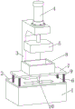
Fig. 1 is a schematic view of the overall structure of a stamping die convenient for demolding according to the present invention;
FIG. 2 is a schematic diagram of a detailed structure of a stamping die convenient for demolding according to the present invention;
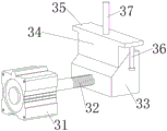
fig. 3 is a schematic view of the overall structure of a demolding mechanism of a stamping die convenient for demolding according to the present invention;
fig. 4 is the utility model relates to a stamping die's demoulding mechanism's installation schematic diagram convenient to drawing of patterns.
In the figure: 1. a mounting seat; 2. mounting a plate; 3. an L-shaped upright post; 4. a hydraulic cylinder; 5. a male die; 6. mounting a column; 7. a base plate; 8. a female die; 9. a buffer spring; 10. a demolding mechanism; 21. a chute; 22. a limiting groove; 23. an opening; 24. a through hole; 31. a servo motor; 32. a threaded rod; 33. a trapezoidal slider; 34. lifting the block; 35. a limiting plate; 36. a limiting column; 37. a thimble; 41. and (4) a top hole.
Detailed Description
In order to make the technical means, creation features, achievement purposes and functions of the present invention easy to understand, the present invention is further described below with reference to the following embodiments.
In the description of the present invention, it should be noted that the terms "upper", "lower", "inner", "outer", "front end", "rear end", "both ends", "one end", "the other end" and the like indicate orientations or positional relationships based on the orientations or positional relationships shown in the drawings, and are only for convenience of description and simplification of description, but do not indicate or imply that the device or element to which the reference is made must have a specific orientation, be constructed in a specific orientation, and be operated, and thus, should not be construed as limiting the present invention. Furthermore, the terms "first" and "second" are used for descriptive purposes only and are not to be construed as indicating or implying relative importance.
In the description of the present invention, it is to be noted that, unless otherwise explicitly specified or limited, the terms "mounted," "disposed," "connected," and the like are to be construed broadly, and for example, "connected" may be either fixedly connected or detachably connected, or integrally connected; can be mechanically or electrically connected; they may be connected directly or indirectly through intervening media, or they may be interconnected between two elements. The specific meaning of the above terms in the present invention can be understood in specific cases to those skilled in the art.
As shown in fig. 1-4, a stamping die convenient to demold, including mount pad 1, 1 upper end fixed mounting of mount pad has mounting panel 2, 2 upper end rear portion fixed mounting of mounting panel has L shape stand 3, 3 upper ends fixed mounting of L shape stand have hydraulic cylinder 4, hydraulic cylinder 4 output runs through L shape stand 3 and fixed mounting has terrace die 5, 2 upper end front portion fixed mounting of mounting panel has two sets of erection column 6, and two sets of erection column 6 are bilateral symmetry and distribute, buffer spring 9 has all been cup jointed to 6 surfaces of two sets of erection column, 6 upper ends common fixed mounting of two sets of erection column have bottom plate 7, 7 upper ends fixed mounting of bottom plate has die 8, and die 8 is located under terrace die 5, be provided with demoulding mechanism 10 in the mount pad 1, and demoulding mechanism 10 extends to bottom plate 7 below.
Open on 1 upper end of mount pad has spout 21, open on 1 upper end of mount pad has two spacing grooves 22, and two spacing grooves 22 use spout 21 to be bilateral symmetry distribution as the center, open on 2 upper ends of mounting panel has opening 23 that link up from top to bottom, and opening 23 is located directly over spout 21, open on 7 upper ends of bottom plate has through-hole 24 that link up from top to bottom, opening 23 is used for restricting limiting plate 35, make limiting plate 35 can only reciprocate, spacing groove 22 and spacing post 36 cooperate, further restrict lifting piece 34, make lifting piece 34 can only carry out vertically vertical movement, through-hole 24 makes things convenient for thimble 37 to wear into in die 8.
The demoulding mechanism 10 comprises a servo motor 31, the front end of the servo motor 31 is fixedly connected with the rear end of the mounting seat 1, the output end of the servo motor 31 penetrates through the rear groove wall of the chute 21 and is fixedly provided with a threaded rod 32, the front end of the threaded rod 32 is movably connected with the front groove wall of the chute 21 through a bearing, the outer surface of the threaded rod 32 is in threaded penetration connection with a trapezoidal sliding block 33, the inclined surface of the upper end of the trapezoidal sliding block 33 is in sliding connection with a lifting block 34, the upper end of the lifting block 34 is fixedly provided with a limiting plate 35, the limiting plate 35 is positioned in the opening 23, the left part and the right part of the lower end of the limiting plate 35 are both fixedly provided with limiting posts 36, the two limiting posts 36 are respectively positioned in the two limiting grooves 22, the upper end of the limiting plate 35 is fixedly provided with a thimble 37, in the initial state, the front end of the trapezoidal sliding block 33 is in contact with the front groove wall of the chute 21, the servo motor 31 rotates forward to drive the threaded rod 32, the threaded rod 32 drives the trapezoidal sliding block 33 to move rightward, the trapezoidal sliding block 33 drives the lifting block 34 to ascend through the upper end inclined plane.
The length of the trapezoidal sliding block 33 is equal to that of the sliding groove 21, the width of the lower portion of the trapezoidal sliding block 33 is equal to half of the width of the sliding groove 21, the limiting column 36 is in sliding connection with the limiting groove 22, and when the rear end of the trapezoidal sliding block 33 is in contact with the rear groove wall of the sliding groove 21, the lifting block 34 ascends to the maximum distance.
The lower wall of the inner cavity of the female die 8 is provided with a top hole 41, the top hole 41 is positioned right above the through hole 24, and the position of the top hole 41 is determined according to the shape of the female die 8.
The thimble 37 is located under the top hole 41, the diameter of the thimble 37 is equal to that of the top hole 41, and the thimble 37 is made of alloy material and is enough to bear the gravity of the ejected workpiece.
It should be noted that, the utility model relates to a stamping die convenient for demolding, when in use, a material is placed in a female die 8, a hydraulic cylinder 4 is started, the output end of the hydraulic cylinder 4 drives a male die 5 to move downwards, a stamping workpiece is formed by stamping raw materials in the female die 8 through the male die 5, when in demolding, a servo motor 31 is started, the output end of the servo motor 31 drives a threaded rod 32 to rotate forwards, the threaded rod 32 drives a trapezoidal slider 33 to move backwards, the trapezoidal slider 33 drives a lifting block 34 to move upwards, the lifting block 34 drives a limiting plate 35 to move upwards, the limiting plate 35 drives a thimble 37 to move upwards, the upper end of the thimble 37 sequentially penetrates through a through hole 24 and a top hole 41 to eject the stamping workpiece in the female die 8, so as to realize rapid demolding of the stamping workpiece, the limiting plate 35 is limited by arranging an opening 23, so that the limiting plate 35 can only move upwards and downwards, and the limiting groove 22 is matched with a limiting column 36, further restriction lifting piece 34 for lifting piece 34 can only carry out vertically vertical removal, and through-hole 24 makes things convenient for thimble 37 to wear into die 8, and the back is accomplished in the drawing of patterns, restarts servo motor 31, and servo motor 31 output reversal makes trapezoidal slider 33 resume to initial position, and thimble 37 descends to initial position, conveniently carries out the punching press of next time, the utility model discloses simple structure, equipment cost is low, convenient to use, and the commonality is strong, and the practicality is strong, is favorable to stamping die's popularization and use.
The basic principles and the main features of the invention and the advantages of the invention have been shown and described above. It will be understood by those skilled in the art that the present invention is not limited to the above embodiments, and that the foregoing embodiments and descriptions are provided only to illustrate the principles of the present invention without departing from the spirit and scope of the present invention. The scope of the invention is defined by the appended claims and equivalents thereof.
Claims (6)
1. The utility model provides a stamping die convenient to drawing of patterns, includes mount pad (1), its characterized in that: the mounting plate (2) is fixedly arranged at the upper end of the mounting seat (1), the L-shaped upright post (3) is fixedly arranged at the rear part of the upper end of the mounting plate (2), the upper end of the L-shaped upright post (3) is fixedly provided with a hydraulic oil cylinder (4), the output end of the hydraulic oil cylinder (4) penetrates through the L-shaped upright post (3) and is fixedly provided with a convex die (5), two groups of mounting columns (6) are fixedly arranged at the front part of the upper end of the mounting plate (2), two groups of mounting columns (6) are symmetrically distributed left and right, buffer springs (9) are sleeved on the outer surfaces of the two groups of mounting columns (6), a bottom plate (7) is fixedly mounted at the upper ends of the two groups of mounting columns (6) together, a concave die (8) is fixedly mounted at the upper end of the bottom plate (7), and the female die (8) is positioned under the male die (5), a demoulding mechanism (10) is arranged in the mounting seat (1), and the demoulding mechanism (10) extends to the lower part of the bottom plate (7).
2. The stamping die for facilitating stripping as claimed in claim 1, wherein: open mount pad (1) upper end has spout (21), open mount pad (1) upper end has two spacing grooves (22), and two spacing grooves (22) use spout (21) to be bilateral symmetry distribution as the center, opening (23) that link up from top to bottom are opened to mounting panel (2) upper end, and opening (23) are located spout (21) directly over, open through-hole (24) that link up from top to bottom on bottom plate (7).
3. The stamping die for facilitating stripping as claimed in claim 1, wherein: the demoulding mechanism (10) comprises a servo motor (31), the front end of the servo motor (31) is fixedly connected with the rear end of the mounting seat (1), the output end of the servo motor (31) penetrates through the rear groove wall of the sliding groove (21) and is fixedly provided with a threaded rod (32), the front end of the threaded rod (32) is movably connected with the front groove wall of the sliding groove (21) through a bearing, the outer surface of the threaded rod (32) is in threaded penetration connection with a trapezoidal sliding block (33), the inclined plane at the upper end of the trapezoidal sliding block (33) is connected with a lifting block (34) in a sliding way, the upper end of the lifting block (34) is fixedly provided with a limiting plate (35), and the limiting plate (35) is positioned in the opening (23), the left part and the right part of the lower end of the limiting plate (35) are both fixedly provided with a limiting column (36), and the two limit columns (36) are respectively positioned in the two limit grooves (22), and the upper end of the limit plate (35) is fixedly provided with a thimble (37).
4. A press die for facilitating stripping as claimed in claim 3, in which: the length of the trapezoidal sliding block (33) is equal to that of the sliding groove (21), the width of the lower portion of the trapezoidal sliding block (33) is equal to half of the width of the sliding groove (21), and the limiting column (36) is connected with the limiting groove (22) in a sliding mode.
5. The stamping die for facilitating stripping as claimed in claim 1, wherein: and the lower wall of the inner cavity of the female die (8) is provided with a top hole (41), and the top hole (41) is positioned right above the through hole (24).
6. A press die for facilitating stripping as claimed in claim 3, in which: the ejector pin (37) is located under the top hole (41), and the diameter of the ejector pin (37) is equal to that of the top hole (41).
Priority Applications (1)
| Application Number | Priority Date | Filing Date | Title |
|---|---|---|---|
| CN202023086199.4U CN213968510U (en) | 2020-12-21 | 2020-12-21 | Stamping die convenient to drawing of patterns |
Applications Claiming Priority (1)
| Application Number | Priority Date | Filing Date | Title |
|---|---|---|---|
| CN202023086199.4U CN213968510U (en) | 2020-12-21 | 2020-12-21 | Stamping die convenient to drawing of patterns |
Publications (1)
| Publication Number | Publication Date |
|---|---|
| CN213968510U true CN213968510U (en) | 2021-08-17 |
Family
ID=77247623
Family Applications (1)
| Application Number | Title | Priority Date | Filing Date |
|---|---|---|---|
| CN202023086199.4U Active CN213968510U (en) | 2020-12-21 | 2020-12-21 | Stamping die convenient to drawing of patterns |
Country Status (1)
| Country | Link |
|---|---|
| CN (1) | CN213968510U (en) |
Cited By (1)
| Publication number | Priority date | Publication date | Assignee | Title |
|---|---|---|---|---|
| CN113978017A (en) * | 2021-10-31 | 2022-01-28 | 九江市杰尼新材料有限公司 | Make things convenient for high-efficient press forming device of metal carbide of drawing of patterns |
-
2020
- 2020-12-21 CN CN202023086199.4U patent/CN213968510U/en active Active
Cited By (1)
| Publication number | Priority date | Publication date | Assignee | Title |
|---|---|---|---|---|
| CN113978017A (en) * | 2021-10-31 | 2022-01-28 | 九江市杰尼新材料有限公司 | Make things convenient for high-efficient press forming device of metal carbide of drawing of patterns |
Similar Documents
| Publication | Publication Date | Title |
|---|---|---|
| CN110465591B (en) | Auto-parts mould convenient to use | |
| CN213968510U (en) | Stamping die convenient to drawing of patterns | |
| CN208827024U (en) | A kind of liftout attachment for vertical injection mould | |
| CN213260901U (en) | Injection mold convenient to drawing of patterns | |
| CN212554814U (en) | Injection mold for small mobile phone parts | |
| CN211807544U (en) | Sole injection mold who possesses automatic bullet material function | |
| CN211334690U (en) | Precise mold demolding device | |
| CN216679597U (en) | Copper shell part cold extrusion forming die device | |
| CN217252163U (en) | Automatic material returning stamping die | |
| CN220482368U (en) | Multifunctional forming die for fiber product | |
| CN219541542U (en) | Stamping die device with quick drawing of patterns | |
| CN219561383U (en) | Zinc bar demoulding device | |
| CN213797852U (en) | Cylinder head mold capable of rapidly demolding | |
| CN214982494U (en) | Combined mold convenient to clamp and assemble | |
| CN214324059U (en) | Demoulding device for injection mould | |
| CN212551332U (en) | Stamping die with secondary ejection mechanism | |
| CN220808381U (en) | Injection mold drawing of patterns and elasticity ejecting device | |
| CN219188619U (en) | Anti-film-pressing shaping device for MIM (metal-insulator-metal) product | |
| CN216100050U (en) | A die-casting assembling die for button processing | |
| CN215550435U (en) | Mould discharge mechanism with locate function | |
| CN216656124U (en) | Refrigerator stamping workpiece extracting device | |
| CN215849875U (en) | Ginseng branch plastic mould | |
| CN215703752U (en) | Cell-phone lens cone device of moulding plastics convenient to mould butt joint | |
| CN219823995U (en) | Glass tableware shaping press | |
| CN211888745U (en) | Inclined plane spring bolt limiting rocker arm blanking die |
Legal Events
| Date | Code | Title | Description |
|---|---|---|---|
| GR01 | Patent grant | ||
| GR01 | Patent grant |