CN213960589U - Heat radiator for electronic and electric equipment - Google Patents
Heat radiator for electronic and electric equipment Download PDFInfo
- Publication number
- CN213960589U CN213960589U CN202022731277.5U CN202022731277U CN213960589U CN 213960589 U CN213960589 U CN 213960589U CN 202022731277 U CN202022731277 U CN 202022731277U CN 213960589 U CN213960589 U CN 213960589U
- Authority
- CN
- China
- Prior art keywords
- box
- electrical equipment
- heat
- dust
- electronic
- Prior art date
- Legal status (The legal status is an assumption and is not a legal conclusion. Google has not performed a legal analysis and makes no representation as to the accuracy of the status listed.)
- Expired - Fee Related
Links
Images


Landscapes
- Cooling Or The Like Of Electrical Apparatus (AREA)
Abstract
The utility model discloses an electron electrical equipment's heat abstractor, the power distribution box comprises a box body, the right side fixed mounting of box has the rose box, the left side fixed mounting of box has bellows, the top fixed mounting of rose box inner chamber has the condenser, the air intake has been seted up at the top of rose box. The utility model discloses a setting of output shaft, can drive the fan of blowing and blow to the box inner chamber, after the inner chamber of wind process box, can go on convulsions to the box inner chamber through the air exhauster, and can absorb the dust simultaneously, can filter the dust through filtering the otter board, it often singly adopts the fan to dispel the heat to have solved current electronic electrical equipment heat abstractor simultaneously, the radiating effect is relatively poor, can't be quick dispel the heat and can not absorb the dust of inside to the important heating component in the electronic electrical equipment, lead to the dust to pile up, influence the problem of equipment normal use.
Description
Technical Field
The utility model relates to an electrical equipment technical field specifically is electron electrical equipment's heat abstractor.
Background
The electric equipment is a general name for equipment such as a generator, a transformer, a power line, a circuit breaker and the like in a power system, the important role played by electric power in our life and production is not ignored, great convenience is brought to us, the electric equipment becomes an important energy source in our production life, the most critical factor for normal operation and transmission of electric power in a power plant is the electric equipment, the existing heat dissipation device of the electronic and electric equipment often singly adopts a fan to dissipate heat, the heat dissipation effect is poor, important heating parts in the electronic and electric equipment cannot be quickly dissipated, and dust in the electric equipment cannot be absorbed, so that dust accumulation is caused, and the normal use of the equipment is influenced.
SUMMERY OF THE UTILITY MODEL
An object of the utility model is to provide an electronic and electrical equipment's heat abstractor possesses the advantage that can dispel the heat fast and can remove dust, has solved current electronic and electrical equipment heat abstractor and often singly adopts the fan to dispel the heat, and the radiating effect is relatively poor, and the important part that generates heat in the unable quick electronic and electrical equipment dispels the heat and can not absorb the dust of inside, leads to the dust to pile up, influences the problem of equipment normal use.
In order to achieve the above object, the utility model provides a following technical scheme: electronic electrical equipment's heat abstractor, the power distribution box comprises a box body, the right side fixed mounting of box has the rose box, the left side fixed mounting of box has bellows, the top fixed mounting of rose box inner chamber has the condenser, the air intake has been seted up at the top of rose box, the top fixedly connected with pipeline of air intake, the top fixed mounting on box right side has the connecting pipe, the right side of connecting pipe and the one end fixed connection of pipeline, the vent has all been seted up to the both sides of bellows, the front of box is rotated and is installed and to open the side door, the positive top fixed mounting of side door has observation window, the thermovent has been seted up to the positive bottom of side door, the fixed surface of thermovent installs the dust guard.
Preferably, an output shaft is fixedly installed in the middle of the inner cavity of the air box, and the top and the bottom of the output shaft are both fixedly connected with a blowing fan.
Preferably, the front surface of the filter box is movably provided with a radiating fin, and the surface of the radiating fin is fixedly provided with a dustproof net.
Preferably, the both sides of rose box inner chamber all fixed mounting have the slide, the inboard activity card of slide is equipped with the filter plate.
Preferably, the two sides of the bottom of the filter box are fixedly provided with connecting blocks, and the inner sides of the connecting blocks are fixedly provided with exhaust fans.
Compared with the prior art, the beneficial effects of the utility model are as follows:
1. the utility model discloses a setting of output shaft, can drive the fan of blowing and blow to the box inner chamber, after the inner chamber of wind process box, can go on convulsions to the box inner chamber through the air exhauster, and can suck the dust simultaneously, can filter the dust through filtering the otter board, and after hot-blast process condenser, can cool off hot-blast fast, realized can dispel the heat to the box inner chamber fast, solved current electron electrical equipment heat abstractor simultaneously often single adoption fan dispels the heat, the radiating effect is relatively poor, can't be quick dispel the heat and can not suck the dust of inside important heating component in to electron electrical equipment, lead to the dust to pile up, influence the problem of equipment normal use.
2. The utility model discloses a setting up of fin has improved heat dispersion, and can drive the filter plate through the setting of slide and extract, washs the change, has increased radiating position through the thermovent, makes the radiating rate improve.
Drawings
FIG. 1 is a schematic structural view of the present invention;
FIG. 2 is a sectional view of the structure of the filtering box of the present invention;
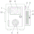
fig. 3 is a front view of the structure of the present invention.
In the figure: 1. a box body; 2. a connecting pipe; 3. a pipeline; 4. a heat dissipation port; 5. a dust-proof plate; 6. an observation window; 7. a filter box; 8. a heat sink; 9. a blowing fan; 10. an output shaft; 11. a vent; 12. an air box; 13. an air inlet; 14. a condenser; 15. a slideway; 16. a filter screen plate; 17. connecting blocks; 18. an exhaust fan; 19. the door is opened laterally.
Detailed Description
The technical solutions in the embodiments of the present invention will be described clearly and completely with reference to the accompanying drawings in the embodiments of the present invention, and it is obvious that the described embodiments are only some embodiments of the present invention, not all embodiments. Based on the embodiments in the present invention, all other embodiments obtained by a person skilled in the art without creative work belong to the protection scope of the present invention.
In the description herein, it is to be understood that the terms "center," "upper," "lower," "front," "rear," "left," "right," "vertical," "horizontal," "top," "bottom," "inner," "outer," and the like are used in the orientations and positional relationships indicated in the drawings to facilitate the description of the patent and to simplify the description, but do not indicate or imply that the referenced device or element must have a particular orientation, be constructed and operated in a particular orientation, and thus are not to be considered limiting of the patent. In the description of the present application, it should be noted that unless otherwise explicitly stated or limited, the terms "mounted," "connected," and "disposed" are to be construed broadly and can, for example, be fixedly connected, disposed, detachably connected, disposed, or integrally connected and disposed. The specific meaning of the above terms in this patent may be understood by those of ordinary skill in the art as appropriate.
Referring to fig. 1-3, a heat dissipating device for electronic and electrical equipment includes a box body 1, a filter box 7 is fixedly installed on the right side of the box body 1, a heat dissipating fin 8 is movably installed on the front surface of the filter box 7, the heat dissipating performance is improved by the installation of the heat dissipating fin 8, a filter screen plate 16 is driven to be extracted by the installation of a slide way 15 for cleaning and replacement, the heat dissipating part is increased by a heat dissipating port 4 to improve the heat dissipating speed, a dust screen is fixedly installed on the surface of the heat dissipating fin 8, the slide ways 15 are fixedly installed on both sides of the inner cavity of the filter box 7, the filter screen plate 16 is movably clamped on the inner side of the slide way 15, an air box 12 is fixedly installed on the left side of the box body 1, an output shaft 10 is fixedly installed on the middle part of the inner cavity of the air box 12, a blowing fan 9 is fixedly connected to the top and the bottom of the output shaft 10, and a condenser 14 is fixedly installed on the top of the inner cavity of the filter box 7, the top of the filter box 7 is provided with an air inlet 13, both sides of the bottom of the filter box 7 are fixedly provided with connecting blocks 17, the inner side of each connecting block 17 is fixedly provided with an exhaust fan 18, the top of the air inlet 13 is fixedly connected with a pipeline 3, the top of the right side of the box body 1 is fixedly provided with a connecting pipe 2, the right side of the connecting pipe 2 is fixedly connected with one end of the pipeline 3, both sides of the air box 12 are provided with ventilation openings 11, the front surface of the box body 1 is rotatably provided with a side opening door 19, the front top of the side opening door 19 is fixedly provided with an observation window 6, the front bottom of the side opening door 19 is provided with a heat dissipation opening 4, the surface of the heat dissipation opening 4 is fixedly provided with a dust guard 5, through the arrangement of an output shaft 10, the air blowing fan 9 can be driven to blow air into the inner cavity of the box body 1, after the air passes through the inner cavity of the box body 1, the air can be sucked into the inner cavity of the box body 1 through the exhaust fan 18, and can simultaneously suck and remove dust, can filter the dust through filter plate 16, and hot-blast behind condenser 14, can cool off hot-blast fast, realized can dispelling the heat fast to box 1 inner chamber, solved current electron electrical equipment heat abstractor simultaneously often singly adopt the fan to dispel the heat, the radiating effect is relatively poor, can't be quick dispel the heat and can not absorb the dust of inside to the important heating part among the electron electrical equipment, lead to the dust to pile up, influence the problem of equipment normal use.
All the components in the utility model are universal standard components or components known by technicians in the field, the structure and principle of the components are known by technicians in the technical manual or known by conventional experimental methods, standard parts used in the application document can be purchased from the market, the components in the application document can be customized according to the description of the specification and the accompanying drawings, the specific connection mode of each component adopts conventional means such as bolts, rivets, welding and the like mature in the prior art, machines, parts and equipment adopt conventional models in the prior art, the control mode is automatically controlled by a controller, a control circuit of the controller can be realized by simple programming of technicians in the field, the components belong to the common knowledge in the field, and the application document is mainly used for protecting mechanical devices, so the control mode and circuit connection are not explained in detail in the application document, no specific description will be made herein.
During the use, through the setting of output shaft 10, can drive fan 9 of blowing and blow to 1 inner chamber of box, behind the inner chamber of wind process box 1, can go on convulsions to 1 inner chamber of box through air exhauster 18, and can absorb the dust simultaneously, can filter the dust through filtering otter board 16, and behind hot-blast 14 condensers, can cool off hot-blast, realized can dispelling the heat to 1 inner chamber of box, heat dispersion has been improved through setting up of fin 8, and can drive through setting up of slide 15 and filter otter board 16 and extract, wash the change, radiating position has been increased through thermovent 4.
Although embodiments of the present invention have been shown and described, it will be appreciated by those skilled in the art that changes, modifications, substitutions and alterations can be made in these embodiments without departing from the principles and spirit of the invention, the scope of which is defined in the appended claims and their equivalents.
Claims (5)
1. Electronic and electrical equipment's heat abstractor, including box (1), its characterized in that: a filter box (7) is fixedly arranged on the right side of the box body (1), an air box (12) is fixedly arranged on the left side of the box body (1), a condenser (14) is fixedly arranged at the top of the inner cavity of the filter box (7), an air inlet (13) is formed at the top of the filter box (7), the top of the air inlet (13) is fixedly connected with a pipeline (3), the top of the right side of the box body (1) is fixedly provided with a connecting pipe (2), the right side of the connecting pipe (2) is fixedly connected with one end of the pipeline (3), both sides of the air box (12) are provided with ventilation openings (11), the front surface of the box body (1) is rotatably provided with a side opening door (19), an observation window (6) is fixedly arranged at the top of the front surface of the side door (19), the heat dissipation opening (4) is formed in the bottom of the front face of the side opening door (19), and the dust guard (5) is fixedly mounted on the surface of the heat dissipation opening (4).
2. The heat dissipating device for electronic and electrical equipment according to claim 1, wherein: an output shaft (10) is fixedly installed in the middle of the inner cavity of the air box (12), and blowing fans (9) are fixedly connected to the top and the bottom of the output shaft (10).
3. The heat dissipating device for electronic and electrical equipment according to claim 1, wherein: the front surface of the filter box (7) is movably provided with a radiating fin (8), and the surface of the radiating fin (8) is fixedly provided with a dustproof net.
4. The heat dissipating device for electronic and electrical equipment according to claim 1, wherein: the filter box is characterized in that slide ways (15) are fixedly mounted on two sides of an inner cavity of the filter box (7), and a filter screen plate (16) is movably clamped on the inner sides of the slide ways (15).
5. The heat dissipating device for electronic and electrical equipment according to claim 1, wherein: the filter box is characterized in that connecting blocks (17) are fixedly mounted on two sides of the bottom of the filter box (7), and exhaust fans (18) are fixedly mounted on the inner sides of the connecting blocks (17).
Priority Applications (1)
| Application Number | Priority Date | Filing Date | Title |
|---|---|---|---|
| CN202022731277.5U CN213960589U (en) | 2020-11-24 | 2020-11-24 | Heat radiator for electronic and electric equipment |
Applications Claiming Priority (1)
| Application Number | Priority Date | Filing Date | Title |
|---|---|---|---|
| CN202022731277.5U CN213960589U (en) | 2020-11-24 | 2020-11-24 | Heat radiator for electronic and electric equipment |
Publications (1)
| Publication Number | Publication Date |
|---|---|
| CN213960589U true CN213960589U (en) | 2021-08-13 |
Family
ID=77210630
Family Applications (1)
| Application Number | Title | Priority Date | Filing Date |
|---|---|---|---|
| CN202022731277.5U Expired - Fee Related CN213960589U (en) | 2020-11-24 | 2020-11-24 | Heat radiator for electronic and electric equipment |
Country Status (1)
| Country | Link |
|---|---|
| CN (1) | CN213960589U (en) |
-
2020
- 2020-11-24 CN CN202022731277.5U patent/CN213960589U/en not_active Expired - Fee Related
Similar Documents
| Publication | Publication Date | Title |
|---|---|---|
| CN216289758U (en) | Air cooling device for control cabinet of electric dust collector | |
| CN213960589U (en) | Heat radiator for electronic and electric equipment | |
| CN211605838U (en) | Ventilation and heat dissipation device of integrated electrical equipment cabinet | |
| CN209962840U (en) | Novel cooling structure of dry-type transformer | |
| CN216481319U (en) | Electrical apparatus box and air condensing units | |
| CN215497876U (en) | High-efficient radiating computer lab switch board | |
| CN213126791U (en) | High server rack of security | |
| CN210428271U (en) | Dustproof computer machine case dispels heat | |
| CN220929718U (en) | Fan device for PCB equipment | |
| CN208227524U (en) | A kind of cabinet ventilation device with labyrinth type water-proof function | |
| CN208425079U (en) | A kind of adjustable telecommunications equipment cabinet of air outlet | |
| CN217545364U (en) | Power equipment protection device | |
| CN219436467U (en) | Electric drive control device | |
| CN211266206U (en) | Air current inner loop formula switch board | |
| CN219961172U (en) | Heat abstractor for be used for relay protection test equipment | |
| CN213520760U (en) | Positive pressure dustproof heat dissipation device of equipment power distribution control box | |
| CN218160003U (en) | Dry-type capacitor shell that waterproof performance is good | |
| CN221240611U (en) | Heat dissipation and ventilation device for power supply equipment | |
| CN217720304U (en) | Electric power centralized cabinet that radiating effect is good | |
| CN210326638U (en) | Novel switch cabinet | |
| CN213214167U (en) | Power adapter with good air cooling and heat dissipation effects | |
| CN221574663U (en) | High-efficient heat abstractor of block terminal | |
| CN219779579U (en) | Dustproof power distribution cabinet | |
| CN212344310U (en) | Heat abstractor for mechanical equipment | |
| CN221042105U (en) | Power distribution cabinet with good heat dissipation performance |
Legal Events
| Date | Code | Title | Description |
|---|---|---|---|
| GR01 | Patent grant | ||
| GR01 | Patent grant | ||
| CF01 | Termination of patent right due to non-payment of annual fee |
Granted publication date: 20210813 |
|
| CF01 | Termination of patent right due to non-payment of annual fee |