CN213923315U - Packaging bubble film cutting device convenient to collect - Google Patents
Packaging bubble film cutting device convenient to collect Download PDFInfo
- Publication number
- CN213923315U CN213923315U CN202022815431.7U CN202022815431U CN213923315U CN 213923315 U CN213923315 U CN 213923315U CN 202022815431 U CN202022815431 U CN 202022815431U CN 213923315 U CN213923315 U CN 213923315U
- Authority
- CN
- China
- Prior art keywords
- film
- film cutting
- arm
- cutting device
- gear
- Prior art date
- Legal status (The legal status is an assumption and is not a legal conclusion. Google has not performed a legal analysis and makes no representation as to the accuracy of the status listed.)
- Active
Links
Images



Abstract
The utility model relates to a bubble chamber film cutting device technical field specifically is a packing bubble chamber film cutting device convenient to collect, including cutting membrane machine and base, the bottom veneer of cutting membrane machine has the base, the upside left end of cutting membrane machine articulates there is the label tape, two sets of pivots are transversely installed through the bearing to the left side front end of label tape, and has cup jointed first gear and second gear in two sets of pivots respectively, the left end of label tape is transversely installed the paper supporting head through the bearing, the rolling has two-sided type scroll from the type on the first gear, and the end of two-sided type scroll is walked around the paper supporting head and is twined on the second gear, two-sided surface equidistance from the type scroll is laminated and is had long five centimetres of single-sided sticky tape. The utility model provides a problem that the fold appears in the bubble chamber membrane when the rolling, improved the fixed difficult problem that receive and releases in end when just rolling up of better bubble chamber membrane, made the more convenient high efficiency of user's work.
Description
Technical Field
The utility model relates to a bubble chamber film cutting device technical field specifically is a packing bubble chamber film cutting device convenient to collect.
Background
The bubble film cutting device is a device for winding and cutting a bubble film, the existing bubble film cutting device has no definite fixing mode when the bubble film is initially wound, and the sealing step is complicated after winding and cutting, if the rolled and cut bubble film is not sealed, the work load is increased, the work efficiency is reduced, and the packaging bubble film cutting device convenient for collection is provided.
SUMMERY OF THE UTILITY MODEL
An object of the utility model is to provide a packing bubble chamber film cutting device convenient to collect to the receipts full bubble chamber film fold that proposes in solving above-mentioned background art, the fixed method of end and cylinder contact surface when no clear fixed bubble chamber film is just rolled up leads to user's work load to increase, the problem that work efficiency reduces.
In order to achieve the above object, the utility model provides a following technical scheme: a packaging bubble film cutting device convenient to collect comprises a film cutting machine and a base, wherein the base is glued to the bottom of the film cutting machine, a label sticking belt is hinged to the left end of the upper side of the film cutting machine, two groups of rotating shafts are transversely installed at the front end of the left side of the label sticking belt through a bearing, a first gear and a second gear are respectively sleeved on the two groups of rotating shafts, a paper pushing head is transversely installed at the left end of the label sticking belt through the bearing, a double-sided release paper roll is wound on the first gear, the end head of the double-sided release paper roll is wound on the second gear through the paper pushing head, a single-sided adhesive tape with the length of five centimeters is attached to the outer surface of the double-sided release paper roll in an equidistance mode, the adhesive surface of the single-sided adhesive tape is attached to the surface of the double-sided release paper roll, a film winding frame is installed on the left side of the upper end of the film cutting machine, a film winding barrel is installed at the top of the film winding frame through the bearing, a motor is fixedly installed at the back end of the film winding frame, and the output end of the motor is fixedly connected with the central shaft of the film winding drum.
Preferably, the end of the double-sided release paper roll forms an acute angle around the paper supporting head, and the acute angle is smaller than thirty degrees.
Preferably, the left end welding of coil stock frame has first top membrane arm, and the upper end of first top membrane arm articulates there is the second top membrane arm, the central point of the articulated department of first top membrane arm and second top membrane arm puts all transversely to have seted up the hole, and transversely inserts in the hole and be equipped with first screw rod, the inner wall of first top membrane arm front end hole is provided with the screw thread with first screw rod looks adaptation, the top membrane pole is transversely installed through the bearing to the upper end front side of second top membrane arm.
Preferably, a rubber pad is glued to the surface of one side, which is attached to the membrane-pushing rod, of the upper end of the first membrane-pushing arm, and anti-skid grains are arranged on the surface of the rubber pad.
Preferably, the top film rod is a cylinder, and the surface of the top film rod is a smooth surface.
Preferably, transversely set up flutedly on rolling up the membrane section of thick bamboo, and transversely install the kelly through the bearing in the recess, and fixed cover has connect the circular arc card on the kelly, the longitudinal section of circular arc card is convex, the one end of kelly is passed a roll membrane section of thick bamboo and is arranged in the outside, the outer end of kelly sets up threaded hole, and threaded hole interpolation is equipped with the second screw rod.
Compared with the prior art, the beneficial effects of the utility model are that: the utility model greatly reduces the generation of folds when the bubble film is rolled, and the end of the bubble film can be better fixed before rolling, and after the rolling and cutting are finished, the cut end can be pasted on the surface of the bubble film, thereby achieving the purpose of fixing;
1. by arranging the first top film arm and the second top film arm, a user can rotate the first screw rod according to the thickness to be rolled before starting the machine, so that the second top film arm rotates on the bearing of the first top film arm to achieve the effect of adjusting the angle, and the bubble film is supported to have the height ideal for the user, thereby solving the problem that the bubble film is wrinkled during rolling;
2. through being provided with kelly and circular arc card, the user exposes in the outside handle of a roll membrane section of thick bamboo through rotating the kelly when fixed bubble chamber membrane rolling for the circular arc card of fixing on the kelly is unscrewed, and the end of bubble chamber membrane supplies the recess of kelly activity on the roll membrane section of thick bamboo by the one end embedding of circular arc card screw-out this moment, reaches fixed effect, can turn back the kelly after all receipts are rolled up, loosen the one end fixed by the circular arc card when just rolling up, cause the convenient high efficiency of whole workflow.
Drawings
FIG. 1 is a schematic sectional view of the front view of the structure of the present invention;
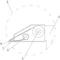
fig. 2 is an enlarged schematic view of the structure at a in fig. 1 according to the present invention;
FIG. 3 is a schematic side view of the structure of the present invention;
fig. 4 is an enlarged schematic view of the structure at B in fig. 3 according to the present invention;
fig. 5 is an enlarged schematic view of the structure at C in fig. 3 according to the present invention;
FIG. 6 is a schematic sectional view of the structure of the present invention from the back;
fig. 7 is an enlarged schematic view of the structure at D in fig. 6 according to the present invention.
In the figure: 1. cutting a film machine; 2. a base; 3. labeling a label tape; 4. a first gear; 5. a second gear; 6. a paper supporting head; 7. double-sided release paper rolls; 8. a coil rack; 9. a first top membrane arm; 10. a first screw; 11. a rubber pad; 12. a second top membrane arm; 13. a membrane-jacking rod; 14. rolling a film drum; 15. a clamping rod; 16. arc cards; 17. a second screw; 18. an electric motor.
Detailed Description
The technical solutions in the embodiments of the present invention will be described clearly and completely with reference to the accompanying drawings in the embodiments of the present invention, and it is obvious that the described embodiments are only some embodiments of the present invention, not all embodiments. Based on the embodiments in the present invention, all other embodiments obtained by a person skilled in the art without creative work belong to the protection scope of the present invention.
Referring to fig. 1-7, the present invention provides an embodiment:
a packaging bubble film cutting device convenient to collect comprises a film cutting machine 1 and a base 2, wherein the base 2 is glued at the bottom of the film cutting machine 1, a label sticking belt 3 is hinged at the left end of the upper side of the film cutting machine 1, two groups of rotating shafts are transversely installed at the front end of the left side of the label sticking belt 3 through a bearing, a first gear 4 and a second gear 5 are respectively sleeved on the two groups of rotating shafts, a paper supporting head 6 is transversely installed at the left end of the label sticking belt 3 through the bearing, a double-sided release paper roll 7 is wound on the first gear 4, the end of the double-sided release paper roll 7 bypasses the paper supporting head 6 and is wound on the second gear 5, a single-sided adhesive tape with the length of five centimeters is pasted on the outer surface of the double-sided release paper roll 7 in an equal distance, the adhesive surface of the single-sided adhesive tape is pasted with the surface of the double-sided release paper roll 7, a film rolling frame 8 is installed on the left side of the upper end of the film cutting machine 1, a film rolling barrel 14 is installed at the top of the film rolling frame 8 through the bearing, the back end of the film rolling frame 8 is fixedly provided with a motor 18, and the output end of the motor 18 is fixedly connected with the central shaft of the film rolling barrel 14;
furthermore, the end of the double-sided release paper roll 7 bypasses the paper supporting head 6 to form an acute angle, and the acute angle is smaller than thirty degrees, so that the sticker on the surface of the double-sided release paper roll 7 can be better peeled off from the surface of the paper supporting head 6, and the cut whole roll of bubble film is sealed and cannot be loosened;
further, a first top film arm 9 is welded at the left end of the coil rack 8, a second top film arm 12 is hinged to the upper end of the first top film arm 9, holes are transversely formed in the centers of the hinged positions of the first top film arm 9 and the second top film arm 12, a first screw 10 is transversely inserted into each hole, threads matched with the first screw 10 are arranged on the inner wall of each hole in the front end of the first top film arm 9, a top film rod 13 is transversely installed on the front side of the upper end of the second top film arm 12 through a bearing, and by means of the structure, the bubble film passing through the surface of the second top film arm 12 is smoothed out before being rolled, and meanwhile, the bubble film is rolled more tightly when being rolled;
furthermore, a rubber pad 11 is glued on the surface of one side, which is attached to the top film rod 13, of the upper end of the first top film arm 9, and anti-skid grains are arranged on the surface of the rubber pad 11, so that the first top film arm 9 can be better clamped when the second top film arm 12 rotates under the rotation of the first screw 10 and the first top film arm 9 is pressed inwards to fix the second top film arm 12, and meanwhile, the conditions that the surfaces of the first top film arm 9 and the second top film arm 12 are not abraded due to long-term tightness and the second top film arm 12 cannot be clamped are protected;
furthermore, the film ejection rod 13 is a cylinder, the surface of the film ejection rod 13 is a smooth surface, and the structure enables the bubble film to be better driven, so that the bubble film cannot be broken due to friction force, and the surface of the bubble film can be smoothed out;
further, transversely set up flutedly on the film winding barrel 14, and transversely install kelly 15 through the bearing in the recess, and fixed cover has connect circular arc card 16 on the kelly 15, the longitudinal section of circular arc card 16 is arc, the one end of kelly 15 is passed film winding barrel 14 and is arranged in the outside, the outer end of kelly 15 is seted up threaded hole, and threaded hole interpolation is equipped with second screw rod 17, and this structure makes the bubble chamber membrane fasten on film winding barrel 14, the rolling of being convenient for, and rotatory second screw rod 17 makes kelly 15 movable at the rolling completion simultaneously, rotates kelly 15 and makes circular arc card 16 revolve round to film winding barrel 14 inside, more convenient the fixed centre gripping to the bubble chamber membrane of having loosened, is convenient for take off the bubble chamber membrane of rolling up.
The working principle is as follows: the user guides one end of the bubble film to the surface of the film rolling cylinder 14 from the upper part of the film jacking rod 13, then rotates the second screw rod 17 to enable the part of the second screw rod 17 embedded into the film rolling cylinder 14 to leave the inner part of the film rolling cylinder 14, then rotates the clamping rod 15, the circular arc card 16 is rotated out under the driving of the clamping rod 15, the rotated end of the circular arc card 16 is abutted to the bubble film and is embedded from the other side, then the first screw rod 10 is rotated to enable the part of the first film jacking arm 9 clamping the second film jacking arm 12 to be released, the angle of the second film jacking arm 12 can be adjusted freely on the first film jacking arm 9 through a bearing, the bubble film is pushed out in the upward slope by the film jacking rod 13, the first film jacking arm 9 is re-clamped after the first screw rod 10 is rotated, the position of the film jacking rod 13 is fixed, the bubble film starts to rotate after the power supply film rolling cylinder 14 is opened, the bubble film is tightly attached to the path at the top end of the second film jacking arm 12, the film tightly attached to the surface of the second film jacking arm 12 under the rotating acting force of the second film rolling cylinder 14 The bubble film is transmitted to the rotating direction of the film rolling cylinder 14 until the required thickness is reached, the grip below the label sticking belt 3 is held, the angle of the label sticking belt 3 is adjusted by a bearing at the middle part of the label sticking belt 3, so that the end of the paper pressing head 6 is stuck to the surface of the rolled bubble film on the film rolling cylinder 14, the rotation of the film rolling cylinder 14 drives the first gear 4 and the second gear 5 in the label sticking belt 3 to rotate, thereby the double-sided release paper roll 7 is taken out, when the double-sided release paper roll 7 is driven to the position of the paper pressing head 6, because the paster attached to the surface of the double-sided release paper roll 7 at an angle is stripped to form a gap, the paster on the surface of the double-sided release paper roll 7 is gradually stripped and attached to one end of the bubble film and the surface of the upper layer of the rolled bubble film, meanwhile, the paper pushing head 6 is stressed and deformed due to the fact that the paper pushing head is pushed against the surface of the rolled bubble film, the sticker is better attached to the cut of the whole roll of bubble film, and the cut is fixed on the surface and cannot be loosened after the whole roll of bubble film is cut.
It is obvious to a person skilled in the art that the invention is not restricted to details of the above-described exemplary embodiments, but that it can be implemented in other specific forms without departing from the spirit or essential characteristics of the invention. The present embodiments are therefore to be considered in all respects as illustrative and not restrictive, the scope of the invention being indicated by the appended claims rather than by the foregoing description, and all changes which come within the meaning and range of equivalency of the claims are therefore intended to be embraced therein. Any reference sign in a claim should not be construed as limiting the claim concerned.
Claims (6)
1. The utility model provides a packing bubble chamber film cutting device convenient to collect, includes film cutting machine and base, its characterized in that: the bottom of the film cutting machine is glued with a base, the left end of the upper side of the film cutting machine is hinged with a label sticking belt, the front end of the left side of the label sticking belt is transversely provided with two groups of rotating shafts through bearings, and the two groups of rotating shafts are respectively sleeved with a first gear and a second gear, the left end of the label sticking belt is transversely provided with a paper supporting head through a bearing, the first gear is wound with a double-sided release paper roll, and the end of the double-sided release paper roll is wound on the second gear by winding the paper supporting head, single-sided adhesive tapes with the length of five centimeters are attached to the outer surface of the double-sided release paper roll at equal intervals, the adhesive surface of the single-sided adhesive tape is attached to the surface of the double-sided release paper roll, a coiling frame is arranged on the left side of the upper end of the film cutting machine, the film winding machine is characterized in that a film winding barrel is mounted at the top of the film winding frame through a bearing, a motor is fixedly mounted at the back end of the film winding frame, and the output end of the motor is fixedly connected with the central shaft of the film winding barrel.
2. The packaged bubble film cutting device convenient for collection according to claim 1, wherein: the end of the double-sided release paper roll forms an acute angle by winding the paper supporting head, and the angle of the acute angle is less than thirty degrees.
3. The packaged bubble film cutting device convenient for collection according to claim 1, wherein: the left end welding of coil stock frame has first top membrane arm, and the upper end of first top membrane arm articulates there is the second top membrane arm, the central point of the articulated department of first top membrane arm and second top membrane arm puts all transversely to have seted up the hole, and transversely inserts in the hole and be equipped with first screw rod, the inner wall of first top membrane arm front end hole is provided with the screw thread with first screw rod looks adaptation, the top membrane pole is transversely installed through the bearing to the upper end front side of second top membrane arm.
4. A packaged bubble film cutting device convenient for collection according to claim 3, wherein: a rubber pad is glued to the surface of one side, attached to the membrane-pushing rod, of the upper end of the first membrane-pushing arm, and anti-skidding grains are arranged on the surface of the rubber pad.
5. A packaged bubble film cutting device convenient for collection according to claim 3, wherein: the film ejection rod is a cylinder, and the surface of the film ejection rod is a smooth surface.
6. The packaged bubble film cutting device convenient for collection according to claim 1, wherein: transversely set up flutedly on the film winding barrel, and transversely install the kelly through the bearing in the recess, and fixed cover has connect the circular arc card on the kelly, the longitudinal section of circular arc card is convex, the one end of kelly is passed a film winding barrel and is arranged in the outside, the outer end of kelly sets up threaded hole, and the threaded hole interpolation is equipped with the second screw rod.
Priority Applications (1)
| Application Number | Priority Date | Filing Date | Title |
|---|---|---|---|
| CN202022815431.7U CN213923315U (en) | 2020-11-27 | 2020-11-27 | Packaging bubble film cutting device convenient to collect |
Applications Claiming Priority (1)
| Application Number | Priority Date | Filing Date | Title |
|---|---|---|---|
| CN202022815431.7U CN213923315U (en) | 2020-11-27 | 2020-11-27 | Packaging bubble film cutting device convenient to collect |
Publications (1)
| Publication Number | Publication Date |
|---|---|
| CN213923315U true CN213923315U (en) | 2021-08-10 |
Family
ID=77145931
Family Applications (1)
| Application Number | Title | Priority Date | Filing Date |
|---|---|---|---|
| CN202022815431.7U Active CN213923315U (en) | 2020-11-27 | 2020-11-27 | Packaging bubble film cutting device convenient to collect |
Country Status (1)
| Country | Link |
|---|---|
| CN (1) | CN213923315U (en) |
-
2020
- 2020-11-27 CN CN202022815431.7U patent/CN213923315U/en active Active
Similar Documents
| Publication | Publication Date | Title |
|---|---|---|
| CN114803035B (en) | Vertical round bottle self-adhesive labeler | |
| CN213923315U (en) | Packaging bubble film cutting device convenient to collect | |
| CN108701869A (en) | A kind of automatic tape-alternation device and cell winding device for electric core winding | |
| CN207876919U (en) | A kind of flexible membrane rolling-up mechanism | |
| CN213443523U (en) | Coiling mechanism that labeller was used | |
| CN116513856B (en) | Full-automatic easy-tearing paste feeding device | |
| CN216762482U (en) | Automatic marking mechanism for hardware production | |
| CN212606388U (en) | Labelling machine | |
| CN213737805U (en) | Rewinding machine with strip sticking mechanism | |
| CN105058953A (en) | Film laminating apparatus and film laminating method | |
| CN214230130U (en) | Multi-layer bottom edge covering device | |
| JP2003118893A (en) | Means for taking up sheet coated with adhesive | |
| CN216426277U (en) | Rubberizing pressure head subassembly for rubberizing equipment | |
| CN220148907U (en) | Low-temperature-resistant bottle adhesive sticker | |
| CN214779993U (en) | Anti-tearing label sticker | |
| CN210555811U (en) | IC card adhesive tape sticking machine capable of preventing adhesive tape from creasing | |
| CN216808687U (en) | Avoid tearing static film non-setting adhesive to paste use device | |
| CN213769288U (en) | Labeling device for mosquito-proof spraying production and processing | |
| CN212981883U (en) | Winding device of PVDC high-barrier coating rewinding machine | |
| CN220710383U (en) | Diaphragm coating protection film composite device | |
| CN217024666U (en) | Coiling mechanism for sticky tape | |
| CN215047498U (en) | Waterproof adhesive tape convenient to cut off | |
| CN215854275U (en) | Two-sided gum of dust protected | |
| CN210102174U (en) | Automatic adhesive tape laminating device for sealing packaging bag | |
| CN214878803U (en) | Rolling shaft capable of preventing aluminum foil paper product from swinging left and right during unreeling |
Legal Events
| Date | Code | Title | Description |
|---|---|---|---|
| GR01 | Patent grant | ||
| GR01 | Patent grant |