SUMMERY OF THE UTILITY MODEL
The utility model discloses an above-mentioned defect that one of the purpose lies in overcoming prior art existence provides an optical device, adjusts the distance of optical lens piece to the laser point of just shooting, solves the deformation that is heated the production and to the influence of light path.
In order to achieve the above purpose, the technical scheme of the utility model is as follows:
an optical device comprises a shell, a sleeve, an optical lens, a focusing nut and a limiting piece, wherein an accommodating cavity is formed in the shell;
the optical lens is fixed in the sleeve, and the sleeve is arranged in the accommodating cavity;
the sleeve is provided with a limiting matching part matched with the limiting part;
the focusing nut is sleeved outside the sleeve and is in threaded connection with the sleeve;
the shell is connected with the focusing nut, the limiting piece is fixedly connected with the shell, and the limiting piece is matched with the limiting matching part to prohibit the sleeve from rotating in the accommodating cavity;
and rotating the focusing nut, and driving the sleeve to move by the focusing nut so as to drive the optical lens to linearly move along the axial direction of the sleeve.
Another object of the present invention is to provide a galvanometer system including the above collimating device.
The third object of the present invention is to provide a laser processing apparatus including the above collimating device and/or the above galvanometer system.
Implement the embodiment of the utility model provides a, will have following beneficial effect:
the embodiment of the utility model provides a through with sleeve and focusing nut threaded connection to use setting element restriction sleeve to rotate holding the intracavity, when rotatory focusing nut, focusing nut drive sleeve motion, thereby drive optical lens and be linear motion along telescopic axis direction together, thereby adjust the distance between optical lens and the light source, in order to reach better light beam regulation effect.
Detailed Description
The technical solutions in the embodiments of the present invention will be described clearly and completely with reference to the accompanying drawings in the embodiments of the present invention, and it is obvious that the described embodiments are only some embodiments of the present invention, not all embodiments. Based on the embodiments in the present invention, all other embodiments obtained by a person skilled in the art without creative efforts belong to the protection scope of the present invention.
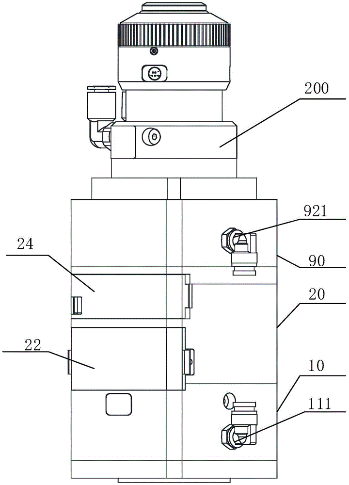
The utility model discloses an optical device 100, refer to fig. 1-3, including casing, sleeve 30, optical lens piece 40, focusing nut 50 and locating part 60, be equipped with in the casing and hold the chamber, in optical lens piece 40 was fixed in sleeve 30, sleeve 30 set up and is holding the intracavity. The sleeve 30 is provided with a limiting matching portion 70 matched with the limiting piece 60, the focusing nut 50 is sleeved outside the sleeve 30 and is in threaded connection with the sleeve 30, the shell is connected with the focusing nut 50, the limiting piece 60 is fixedly connected with the shell, the limiting piece 60 is matched with the limiting matching portion 70 to prohibit the sleeve 30 from rotating in the containing cavity, the focusing nut 50 is rotated, and the focusing nut 50 drives the sleeve 30 to move, so that the optical lens 40 is driven to linearly move along the axial direction of the sleeve 30, and the distance between the optical lens 40 and the light source is adjusted.
The optical lens 40 may be a collimating lens, and when the optical lens is a collimating lens, the collimation of the parallel light beams can be adjusted by adjusting the distance between the optical lens 40 and the light source. The optical lens 40 may also be a focusing lens, and when the optical lens is a focusing lens, a better focusing effect can be achieved by adjusting a distance between the optical lens 40 and the light source.
Specifically, the focusing nut 50 has an internal thread, the sleeve 30 has an external thread matching the internal thread, the focusing nut 50 is rotated for one circle, the sleeve 30 moves linearly along the axial direction by a thread pitch, the smaller the thread pitch, the greater the focusing precision, in this embodiment, the thread pitches of the external thread and the internal thread are preferably 1mm to 5mm, and the better adjustment precision can be obtained.
Preferably, in this embodiment, the position-limiting member 60 is a position-limiting bolt, and the position-limiting engaging portion 70 is a position-limiting groove opened on the outer wall of the sleeve 30. The side wall of the second housing 20 is provided with a mounting hole through which a stopper bolt passes and the end of which is inserted into a stopper groove.
Preferably, in this embodiment, the housing includes a first housing 10 and a second housing 20, the first housing 10 and the second housing 20 are coaxially connected, and the sleeve 30 drives the optical lens 40 to move in the first housing 10.
In order to reduce the influence of the thermal effect of the light source on the optical lens 40, the optical device 100 preferably further comprises an optical lens cooling module. Preferably, in this embodiment, the optical lens cooling module includes a first liquid inlet block 11 having a first storage chamber for cooling liquid and a first liquid outlet block 12 having a second storage chamber for cooling liquid, the first liquid inlet block 11 is communicated with the first liquid outlet block 12, the first liquid inlet block 11 has a first inlet 111 and a first outlet, the first liquid outlet block 12 has a second outlet 121 and a second inlet, the first outlet is communicated with the second inlet, external cooling liquid enters the first liquid inlet block 11 from the first inlet 111, fills the first liquid inlet block 11, flows out from the first outlet and enters the first liquid outlet block 12 through the second inlet, fills the first liquid outlet block 12, and flows out from the second outlet 121, the flow direction of the cooling liquid in the first liquid inlet block 11 is opposite to the flow direction of the cooling liquid in the first liquid outlet block 12, and the first liquid inlet block 11 and the first liquid outlet block 12 are cooperatively connected to form the first housing 10. Because the flow direction of the cooling liquid in the first liquid inlet block 11 is opposite to that of the cooling liquid in the first liquid outlet block 12, the heat exchange efficiency between the first liquid inlet block 11 and the first liquid outlet block 12 can be improved, and therefore the heat exchange efficiency between the first liquid outlet block 12 and the optical lens can be improved.
Preferably, the housing further has a mounting cavity 52, the focusing nut 50 is disposed in the mounting cavity 52, the housing further has a first opening 21 communicated with the mounting cavity 52, and the first opening 21 is used for rotating the focusing nut 50.
In this embodiment, the end of the second casing 20 connected to the first casing 10 is provided with a mounting cavity 52, the mounting cavity 52 is coaxial with the accommodating cavity, and the first opening 21 is provided in the side wall of the second casing 20.
Preferably, the first opening 21 is covered with a first cover 22 to prevent dust from entering the seating chamber 52. Specifically, in this embodiment, the first cover 22 is connected to the second housing 20 through a rotating shaft, a first buckle is installed at one end of the first cover 22, and a first protrusion is disposed on the second housing 20, and the first buckle and the first protrusion cooperate to lock the first cover 22.
Preferably, the optical device 100 further comprises a protective lens 80, the protective lens 80 being coaxially fixed within the receiving cavity.
In order to reduce the thermal effect of the light source on the protective lens 80, the optical device 100 preferably further comprises a protective lens cooling module. Preferably, the protective lens cooling module includes a second liquid inlet block 91 having a third storage cavity for cooling liquid and a second liquid outlet block 92 having a fourth storage cavity for cooling liquid, the second liquid inlet block 91 is communicated with the second liquid outlet block 92, the second liquid inlet block 91 has a third inlet 911 and a third outlet, the second liquid outlet block 92 has a fourth outlet 921 and a fourth inlet, the third outlet is communicated with the fourth inlet, cooling liquid enters the second liquid inlet block 91 from the third inlet 911, fills the second liquid inlet block 91, flows out from the third outlet and enters the second liquid outlet block 92 through the fourth inlet, fills the second liquid outlet block 92, flows out from the fourth outlet 921, the flow direction of cooling liquid in the second liquid inlet block 91 is opposite to the flow direction of cooling liquid in the second liquid outlet block 92, the second liquid inlet block 91 and the second liquid outlet block 92 are cooperatively connected to form a third housing 90, and the third housing 90 is coaxially connected to the second housing 20.
Preferably, the protection lens 80 is disposed on the supporting seat 82, the supporting seat 82 is shaped like a drawer, a first counterbore for installing the supporting seat 82 is disposed at the end of the second casing 20 away from the first casing 10, the first counterbore is coaxial with the accommodating cavity, a second opening 23 communicated with the first counterbore is disposed on the side wall of the second casing 20, and the second opening 23 is used for the supporting seat 82 to go in and out, so as to install and detach the protection lens 80.
Preferably, a second cover body 24 is covered on the second opening 23. Specifically, in this embodiment, the second cover 24 is connected to the second housing 20 through a rotating shaft, a second buckle is installed at one end of the second cover 24, a second protrusion is disposed on the second housing 20, and the second buckle and the second protrusion cooperate to lock the second cover 24.
Third inlet 911 fourth outlet 921 the third inlet 911 fourth outlet 921 preferably has an inner diameter smaller than the diameter of the first counterbore, a first pressing member 84 is provided between the protective lens 80 and the third housing 90, and the first pressing member 84 abuts against the third housing 90 for pressing and fixing the protective lens 80.
One end of the sleeve 30 is provided with a second counter bore coaxial with the sleeve 30, the diameter of the second counter bore is smaller than the outer diameter of the sleeve 30 and larger than the inner diameter of the sleeve 30, the second counter bore is coaxial with the accommodating cavity, the optical lens 40 is coaxially arranged in the second counter bore, and the optical lens 40 is fixed in the sleeve 30 through a second pressing piece 42.
Preferably, the second compression member 42 is threadedly coupled to the sleeve 30. In this embodiment, the end of the sleeve 30 has an internal thread, the second pressing member 42 has an external thread, and the second pressing member 42 presses and fixes the optical lens 40 in the second counter bore.
Preferably, a sealing structure is designed at the joint of each part, so that the dustproof effect is realized on the whole. Specifically, sealing members are disposed between the first liquid inlet block 11 and the first liquid outlet block 12, between the first housing 10 and the focusing nut 50, between the focusing nut 50 and the second housing 20, between the second housing 20 and the third housing 90, between the second liquid inlet block 91 and the second liquid outlet block 92, and between the third housing 90 and the laser head mounting member 200.
A galvanometer system includes the optical device 100 for collimating and adjusting light entering the galvanometer system.
A laser processing device comprises the optical device 100 or the galvanometer system and further comprises a laser head installation piece 200, and a laser head is arranged in the laser head installation piece 200. The laser head mount 200 is connected to the third housing 90.
Preferably, the laser head mount 200 further comprises a cooling module for cooling the laser emitting end, and the laser head mount has a cooling cavity in a side wall thereof, and a cooling fluid inlet 201 and a cooling fluid outlet 202 on the side wall, which are respectively connected to external cooling fluid pipes.
The above-mentioned embodiments only express several embodiments of the present invention, and the description thereof is more specific and detailed, but not construed as limiting the claims. It should be noted that, for those skilled in the art, without departing from the spirit of the present invention, several variations and modifications can be made, which are within the scope of the present invention. Therefore, the protection scope of the present invention should be subject to the appended claims.