CN213916121U - Lathe feeding equipment - Google Patents
Lathe feeding equipment Download PDFInfo
- Publication number
- CN213916121U CN213916121U CN202022284166.4U CN202022284166U CN213916121U CN 213916121 U CN213916121 U CN 213916121U CN 202022284166 U CN202022284166 U CN 202022284166U CN 213916121 U CN213916121 U CN 213916121U
- Authority
- CN
- China
- Prior art keywords
- lead screw
- motor
- sliding plate
- fine setting
- slide
- Prior art date
- Legal status (The legal status is an assumption and is not a legal conclusion. Google has not performed a legal analysis and makes no representation as to the accuracy of the status listed.)
- Expired - Fee Related
Links
- 238000003754 machining Methods 0.000 abstract description 14
- 238000006073 displacement reaction Methods 0.000 abstract description 2
- 230000008878 coupling Effects 0.000 description 2
- 238000010168 coupling process Methods 0.000 description 2
- 238000005859 coupling reaction Methods 0.000 description 2
- 238000012986 modification Methods 0.000 description 2
- 230000004048 modification Effects 0.000 description 2
- 230000001133 acceleration Effects 0.000 description 1
- 238000005516 engineering process Methods 0.000 description 1
- 230000006872 improvement Effects 0.000 description 1
- 238000009434 installation Methods 0.000 description 1
- 230000009467 reduction Effects 0.000 description 1
- 230000004044 response Effects 0.000 description 1
Images


Landscapes
- Turning (AREA)
Abstract
The utility model relates to a lathe feeder equipment, comprises a workbench, first lead screw subassembly, second lead screw subassembly, fine setting platform and chuck, be provided with first guide rail on the workstation, first lead screw subassembly includes first slide, first lead screw, first slider and first motor, second lead screw subassembly includes the second slide, the second lead screw, second slider and second motor, first lead screw subassembly movable mounting is on the workstation, the perpendicular movable mounting of second lead screw subassembly activity is on first lead screw subassembly, the one end that the second slide deviates from the second slider is provided with the mounting bracket, fine setting platform one end can be dismantled with the mounting bracket and be connected, fine setting platform is perpendicular with the workstation, the chuck is installed on the other end of fine setting platform. The utility model discloses set up horizontal, the longitudinal displacement of mutually perpendicular's first lead screw subassembly and second lead screw subassembly drive work piece at the workstation, the distance between automatic adjustment work piece and the cutter to use the angle of processing of fine setting platform cooperation chuck adjustment work piece, improve the machining precision.
Description
Technical Field
The utility model relates to a mechanical equipment technical field especially relates to a lathe feeder equipment.
Background
The numerical control lathe is a high-precision and high-precision automatic lathe, and workpieces in different shapes can be machined by carrying various cutters.
With the rapid development of science and technology, the updating speed of electromechanical products is accelerated, and the requirements on the precision and surface quality of part processing are higher and higher. In order to meet the requirements of the complex and changeable market, the current lathe is developed in the forward high-speed cutting, dry cutting and quasi-dry cutting directions, and the workpiece machining precision is also continuously improved. At present, a lathe feeding device generally directly uses a locking clamp to clamp a workpiece, and then adopts a screw rod structure to drive the workpiece to be close to a tool bit for processing. The feeding structure enables the workpiece to move back and forth only in one direction, when the machining angle needs to be adjusted, the workpiece can be loosened from the locking clamp only after the cutter is withdrawn, and the workpiece is clamped again after the installation direction is adjusted, so that the machining efficiency is low. And because the work piece can only a direction displacement, to some parts that need the finish machining, the interval between cutter and the work piece is not good to be adjusted, leads to the machining precision not up to standard.
SUMMERY OF THE UTILITY MODEL
Therefore, it is necessary to provide a lathe feeding device aiming at the condition that the existing lathe feeding device is inconvenient to adjust the machining angle of a workpiece, the workbench is provided with a first lead screw assembly and a second lead screw assembly which are perpendicular to each other to drive the workpiece to move transversely and longitudinally, the distance between the workpiece and a cutter is convenient to automatically adjust, the fine adjustment platform is matched with the chuck to adjust the machining angle of the workpiece, and the machining precision is improved.
A lathe feeding device comprises a workbench, a first lead screw assembly, a second lead screw assembly, a fine adjustment platform and a chuck, wherein a first guide rail is arranged on the workbench, the first lead screw assembly comprises a first sliding plate, a first lead screw, a first sliding block and a first motor, the lower end of the first sliding plate is movably connected with the first guide rail, the first sliding block is movably sleeved on the first lead screw, the first motor is arranged on the workbench, the output end of the first motor is connected with the end part of the first lead screw, the first sliding plate is connected with the first sliding block in parallel, a second guide rail which is perpendicular to the first guide rail is arranged at the upper end of the first sliding plate, the second lead screw assembly comprises a second sliding plate, a second lead screw, a second sliding block and a second motor, the lower end of the second sliding plate is movably connected with the second guide rail, the second sliding block is movably sleeved on the second lead screw, the second motor is installed on the first slide, the second motor output with second lead screw end connection, the second slide with the second slider is connected side by side, the second slide deviates from the one end of second slider is provided with the mounting bracket, fine setting platform one end with the connection can be dismantled to the mounting bracket, the fine setting platform with the workstation is perpendicular, the chuck is installed on the other end of fine setting platform.
Preferably, the end parts of the first sliding plate and the second sliding plate are detachably connected with connecting pieces, and one ends of the connecting pieces are provided with through holes.
Preferably, the first motor and the second motor are respectively connected with the first screw rod and the second screw rod through couplers.
Preferably, the first sliding block and the second sliding block respectively comprise a sleeve and a baffle, the baffle is installed at the end part of the sleeve and communicated with the sleeve, the sleeve is inserted into the through hole, and the baffle is connected with the end part of the connecting piece through a bolt.
Preferably, the workbench and the first sliding plate are respectively provided with a mounting seat for mounting the first screw rod and the second screw rod.
The utility model discloses an useful part lies in: 1. the first lead screw assembly and the second lead screw assembly which are stacked and perpendicular are arranged on the workbench, so that the workpiece can be conveniently driven to transversely and longitudinally displace, the distance between the workpiece and the cutter can be conveniently adjusted, the first sliding plate is connected with the first sliding block in parallel, and the second sliding plate is connected with the second sliding block in parallel, so that the length of the workbench is reduced, and the overall volume of the feeding equipment is reduced; 2. the fine adjustment platform is used for finely adjusting the rotation angle of the chuck and the distance between the workpiece clamped on the chuck and the cutter, the workpiece does not need to be detached from the chuck for adjustment, the machining efficiency is improved, the cutter is convenient to grind and finish the workpiece, and the machining quality of the workpiece is improved.
Drawings
FIG. 1 is a schematic perspective view of a lathe feeder apparatus according to one embodiment;
FIG. 2 is an enlarged view of portion A of FIG. 1;
FIG. 3 is a perspective view of a lathe feeder from another perspective;
FIG. 4 is a perspective view of the connector;
fig. 5 is a perspective view of the first slider or the second slider.
Detailed Description
In order to make the above objects, features and advantages of the present invention more comprehensible, embodiments of the present invention are described in detail below with reference to the accompanying drawings. In the following description, numerous specific details are set forth in order to provide a thorough understanding of the present invention. The present invention may, however, be embodied in many different forms and should not be construed as limited to the embodiments set forth herein, as those skilled in the art will be able to make similar modifications without departing from the spirit and scope of the present invention.
It will be understood that when an element is referred to as being "secured to" or "disposed on" another element, it can be directly on the other element or intervening elements may also be present. When an element is referred to as being "connected" to another element, it can be directly connected to the other element or intervening elements may also be present. The terms "vertical," "horizontal," "left," "right," and the like as used herein are for illustrative purposes only and do not represent the only embodiments.
Unless defined otherwise, all technical and scientific terms used herein have the same meaning as commonly understood by one of ordinary skill in the art to which this invention belongs. The terminology used herein in the description of the invention is for the purpose of describing particular embodiments only and is not intended to be limiting of the invention. As used herein, the term "and/or" includes any and all combinations of one or more of the associated listed items.
As shown in fig. 1 to 3, a lathe feeding device includes a workbench 1, a first lead screw assembly 2, a second lead screw assembly 3, a fine tuning platform 4 and a chuck 5, a first guide rail 11 is disposed on the workbench 1, the first lead screw assembly 2 includes a first sliding plate 21, a first lead screw 22, a first slider 23 and a first motor 24, the lower end of the first sliding plate 21 is movably connected with the first guide rail 11, the first slider 23 is movably sleeved on the first lead screw 22, the first motor 24 is mounted on the workbench 1, the output end of the first motor 24 is connected with the end of the first lead screw 22, the first sliding plate 21 is connected with the first slider 23 in parallel, a second guide rail 12 perpendicular to the first guide rail 11 is disposed at the upper end of the first sliding plate 21, and the second lead screw assembly 3 includes a second sliding plate 31, a second lead screw 32, Second slider 33 and second motor 34, second slide 31 lower extreme with second guide rail 12 swing joint, second slider 33 movable sleeve is established on the second lead screw 32, second motor 34 is installed on first slide 21, second motor 34 output with second lead screw 32 end connection, second slide 31 with second slider 33 is connected side by side, second slide 31 deviates from the one end of second slider 33 is provided with mounting bracket 6, fine setting platform 4 one end with the connection can be dismantled to mounting bracket 6, fine setting platform 4 with workstation 1 is perpendicular, chuck 5 is installed on fine setting platform 4's the other end. Specifically, in the present embodiment, the first screw assembly 2 and the second screw assembly 3 are mounted on the table 1 in a stacked manner, so that a workpiece (not shown) clamped on the driving chuck 5 can be driven to freely move along the X direction and the Y direction, the distance between the workpiece and the tool and the grinding position can be freely adjusted, and the grinding efficiency can be improved. Further, chuck 5 is installed on second lead screw subassembly 3 through fine setting platform 4, use fine setting platform 4 can finely tune the interval between the work piece of centre gripping and the cutter on chuck 5, and can rotate chuck 5 on vertical plane, and then the angle between adjustment work piece and the cutter, carry out abrasive machining again, need not to dismantle the work piece from chuck 5, assemble processing again behind the angle adjustment, very big improvement work piece abrasive machining's efficiency, and fine setting platform 4's X is to reaching Y to distance and angular adjustment precision height, guarantee the grinding quality between work piece and the cutter, realize the finish machining. The first screw rod assembly 2 and the second screw rod assembly 3 are installed in a stacked mode, so that the floor area is small, the first motor 24 and the second motor 34 are high in driving speed, good in acceleration and deceleration characteristics and excellent in response characteristics and following accuracy. And, first slide 21 is connected with first slider 23 side by side, second slide 31 with second slider 33 is connected side by side, then need not to set up first guide rail 11 and first lead screw 22 and second guide rail 12 and second lead screw 32 on same straight line, very big reduction workstation 1's length, and then reduced feeder equipment and taken up the volume.
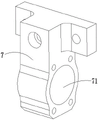
As shown in fig. 1 to 4, the end portions of the first sliding plate 21 and the second sliding plate 31 are detachably connected with a connecting member 7, and one end of the connecting member 7 is provided with a through hole 71. Specifically, in this embodiment, the connecting member 7 is used to connect the sliding plate and the sliding block, so that the first sliding plate 21 is arranged side by side with the first sliding block 23, the second sliding plate 31 is arranged side by side with the second sliding block 33, and the connecting member 7 is provided with the through hole 71, which is convenient for inserting the end portions of the first sliding block 23 and the second sliding block 33 into the through hole 71, thereby improving the connection strength.
As shown in fig. 1 to 3, the first motor 24 and the second motor 34 are respectively connected to the first lead screw 22 and the second lead screw 32 through a coupling 8. Specifically, in the present embodiment, when the first motor 24 and the second motor 34 drive the first lead screw 22 and the second lead screw 32 to rotate, the coupling 8 plays a role of overload protection, and prevents the first lead screw 22 and the second lead screw 32 from bearing an excessive load.
As shown in fig. 1 to 5, the first slider 23 and the second slider 33 respectively include a sleeve 231 and a baffle 232, the baffle 232 is mounted at an end of the sleeve 231 and is communicated with the sleeve 231, the sleeve 231 is inserted into the through hole 71, and the baffle 232 is connected with an end of the connecting member 7 by a bolt. Specifically, in this embodiment, a threaded structure is disposed in the sleeve 231, so that the sleeve 231 is spirally connected to the first lead screw 22 and the second lead screw 32, and therefore, when the motor drives the lead screw to rotate, the sleeve 231 can move back and forth on the lead screw, the sleeve 231 is inserted into the through hole 71, and the baffle 232 is connected to the connecting member 7 by a bolt, so as to drive the sliding plate to move synchronously.
As shown in fig. 2, the table 1 and the first slide plate 21 are respectively provided with a mounting base 13 for mounting a first lead screw 22 and a second lead screw 32.
The technical features of the embodiments described above may be arbitrarily combined, and for the sake of brevity, all possible combinations of the technical features in the embodiments described above are not described, but should be considered as being within the scope of the present specification as long as there is no contradiction between the combinations of the technical features.
The above-mentioned embodiments only represent some embodiments of the present invention, and the description thereof is specific and detailed, but not to be construed as limiting the scope of the present invention. It should be noted that, for those skilled in the art, without departing from the spirit of the present invention, several variations and modifications can be made, which are within the scope of the present invention. Therefore, the protection scope of the present invention should be subject to the appended claims.
Claims (5)
1. A lathe feeding device is characterized in that: comprises a workbench, a first lead screw component, a second lead screw component, a fine adjustment platform and a chuck, wherein a first guide rail is arranged on the workbench, the first lead screw component comprises a first sliding plate, a first lead screw, a first slide block and a first motor, the lower end of the first sliding plate is movably connected with the first guide rail, the first slide block is movably sleeved on the first lead screw, the first motor is arranged on the workbench, the output end of the first motor is connected with the end part of the first lead screw, the first sliding plate is connected with the first slide block in parallel, the upper end of the first sliding plate is provided with a second guide rail which is mutually vertical to the first guide rail, the second lead screw component comprises a second sliding plate, a second lead screw, a second slide block and a second motor, the lower end of the second sliding plate is movably connected with the second guide rail, the second slide block is movably sleeved on the second lead screw, the second motor is installed on the first slide, the second motor output with second lead screw end connection, the second slide with the second slider is connected side by side, the second slide deviates from the one end of second slider is provided with the mounting bracket, fine setting platform one end with the connection can be dismantled to the mounting bracket, the fine setting platform with the workstation is perpendicular, the chuck is installed on the other end of fine setting platform.
2. The lathe feeder apparatus of claim 1, wherein: the first sliding plate and the end part of the second sliding plate are detachably connected with a connecting piece, and a through hole is formed in one end of the connecting piece.
3. The lathe feeding apparatus as set forth in claim 2, wherein: the first motor and the second motor are respectively connected with the first screw rod and the second screw rod through couplers.
4. A lathe feeder apparatus as defined in claim 3, wherein: the first sliding block and the second sliding block respectively comprise a sleeve and a baffle, the baffle is arranged at the end part of the sleeve and communicated with the sleeve, the sleeve is inserted in the through hole, and the baffle is connected with the end part of the connecting piece through a bolt.
5. The lathe feeding apparatus as set forth in claim 4, wherein: and the workbench and the first sliding plate are respectively provided with a mounting seat for mounting the first screw rod and the second screw rod.
Priority Applications (1)
| Application Number | Priority Date | Filing Date | Title |
|---|---|---|---|
| CN202022284166.4U CN213916121U (en) | 2020-10-14 | 2020-10-14 | Lathe feeding equipment |
Applications Claiming Priority (1)
| Application Number | Priority Date | Filing Date | Title |
|---|---|---|---|
| CN202022284166.4U CN213916121U (en) | 2020-10-14 | 2020-10-14 | Lathe feeding equipment |
Publications (1)
| Publication Number | Publication Date |
|---|---|
| CN213916121U true CN213916121U (en) | 2021-08-10 |
Family
ID=77162384
Family Applications (1)
| Application Number | Title | Priority Date | Filing Date |
|---|---|---|---|
| CN202022284166.4U Expired - Fee Related CN213916121U (en) | 2020-10-14 | 2020-10-14 | Lathe feeding equipment |
Country Status (1)
| Country | Link |
|---|---|
| CN (1) | CN213916121U (en) |
-
2020
- 2020-10-14 CN CN202022284166.4U patent/CN213916121U/en not_active Expired - Fee Related
Similar Documents
| Publication | Publication Date | Title |
|---|---|---|
| CN109848451B (en) | Cutter disc structure of numerical control lathe | |
| CN211249228U (en) | High-positioning milling machine | |
| CN110936160A (en) | Numerical control turning and milling composite all-in-one machine | |
| CN111531186A (en) | Profiling component for machining cambered surface of lathe | |
| CN213916121U (en) | Lathe feeding equipment | |
| CN220312439U (en) | Double-spindle double-tool tower turning and milling composite machine tool | |
| CN217701671U (en) | Horizontal gear edge milling machine | |
| CN105328492A (en) | Main transmission system of horizontal numerical control boring and milling machine | |
| CN211991101U (en) | Double-end numerical control turn-milling all-in-one | |
| CN211162890U (en) | Horizontal drilling and milling machine structure | |
| CN210305905U (en) | Full-automatic inverted ball cage inclined channel rough and finish milling special machine tool | |
| CN207746818U (en) | A kind of piston pin hole and pin hole inner shield ring slot are integrally machined tooling | |
| CN216858901U (en) | Feeding device for machine tool equipment and machine tool equipment | |
| CN221658668U (en) | Machine tool with automatic positioning and clamping functions | |
| CN220498397U (en) | Multi-degree-of-freedom machine tool machining and measuring device | |
| CN214488845U (en) | Multi-shaft vertical lathe | |
| CN211490603U (en) | Numerical control lathe | |
| CN219747184U (en) | Mechanical transmission mechanism of numerical control machine tool | |
| CN220462268U (en) | Chuck for lathe | |
| CN220028764U (en) | Shaft part boring outer circle tool | |
| CN218080594U (en) | Sliding table opening flattening machine | |
| CN105328495A (en) | X-direction, Y-direction and Z-direction drive system of horizontal type numerical control boring and milling machine | |
| CN105328229A (en) | Horizontal type numerical control boring and milling machine | |
| CN218575509U (en) | Double-cutter tower turning and milling composite device | |
| CN221791859U (en) | Boring fixture |
Legal Events
| Date | Code | Title | Description |
|---|---|---|---|
| GR01 | Patent grant | ||
| GR01 | Patent grant | ||
| CF01 | Termination of patent right due to non-payment of annual fee | ||
| CF01 | Termination of patent right due to non-payment of annual fee |
Granted publication date: 20210810 |