CN213914872U - Full-automatic powder removing machine - Google Patents
Full-automatic powder removing machine Download PDFInfo
- Publication number
- CN213914872U CN213914872U CN202022818513.7U CN202022818513U CN213914872U CN 213914872 U CN213914872 U CN 213914872U CN 202022818513 U CN202022818513 U CN 202022818513U CN 213914872 U CN213914872 U CN 213914872U
- Authority
- CN
- China
- Prior art keywords
- dust
- shell
- discharger
- collecting
- automatic powder
- Prior art date
- Legal status (The legal status is an assumption and is not a legal conclusion. Google has not performed a legal analysis and makes no representation as to the accuracy of the status listed.)
- Expired - Fee Related
Links
- 239000000843 powder Substances 0.000 title claims abstract description 23
- 239000000428 dust Substances 0.000 claims abstract description 133
- 239000000463 material Substances 0.000 claims abstract description 30
- 238000000605 extraction Methods 0.000 claims abstract description 6
- 238000000926 separation method Methods 0.000 claims description 30
- 239000002245 particle Substances 0.000 claims description 20
- 239000004744 fabric Substances 0.000 claims description 11
- 238000007664 blowing Methods 0.000 claims description 5
- 235000012054 meals Nutrition 0.000 abstract description 2
- 230000000694 effects Effects 0.000 description 11
- 238000010586 diagram Methods 0.000 description 8
- 238000000034 method Methods 0.000 description 5
- 239000000203 mixture Substances 0.000 description 3
- 238000005086 pumping Methods 0.000 description 3
- 238000003466 welding Methods 0.000 description 3
- 229910000831 Steel Inorganic materials 0.000 description 2
- 238000010521 absorption reaction Methods 0.000 description 2
- 230000003111 delayed effect Effects 0.000 description 2
- 238000001914 filtration Methods 0.000 description 2
- 239000008187 granular material Substances 0.000 description 2
- 230000014759 maintenance of location Effects 0.000 description 2
- 230000002035 prolonged effect Effects 0.000 description 2
- 239000010959 steel Substances 0.000 description 2
- 230000009286 beneficial effect Effects 0.000 description 1
- 239000013590 bulk material Substances 0.000 description 1
- 239000012141 concentrate Substances 0.000 description 1
- 230000005484 gravity Effects 0.000 description 1
- 238000012986 modification Methods 0.000 description 1
- 230000004048 modification Effects 0.000 description 1
- 230000002441 reversible effect Effects 0.000 description 1
- 239000002699 waste material Substances 0.000 description 1
Images


Landscapes
- Filtering Of Dispersed Particles In Gases (AREA)
Abstract
The utility model provides a full-automatic meal removing machine, include: the control circuit, the hoister, the separating shell and the bag-type dust removing devices are symmetrically arranged on two sides of the separating shell; at least two collecting hoppers are arranged in the separating shell from top to bottom, a material scattering plate is arranged in the middle below the collecting hoppers, and dust extraction ports are formed in the separating shell on the two sides of each collecting hopper; the bag-type dust collector is provided with a dust collecting shell connected with the separating shell, the dust collecting shell is provided with a dust collecting opening corresponding to the dust suction opening, the top of the dust collecting shell is connected with a fan through an induced duct, and the bottoms of the two bag-type dust collectors are respectively provided with a first discharger and a second discharger; the bag-type dust collector can intensively absorb and treat dust, so that the environment pollution caused by dust escape is avoided; the automatic control of the powder removing machine is realized, manual intervention is reduced, the working efficiency of the equipment can be improved, and parameters of the hoister and the fan can be set through a human-computer interface.
Description
Technical Field
The utility model belongs to the technical field of the cornmill, concretely relates to full-automatic cornmill.
Background
The powder remover is also called a particle bed filter dust remover, and the particle bed filter dust remover adopts a high-temperature resistant particle filter material, and has unique advantages in the field of high-temperature gas dust removal.
In the prior art, as the chinese utility model patent with application number CN201620833125.7, a particle bed dust remover is disclosed, which comprises an outer shell and at least one layer of particle bed filter arranged inside the outer shell along the vertical direction, the upper part of the outer shell is provided with a dust-containing gas inlet, the lower part of the outer shell is provided with a dust discharge port, each layer of particle bed filter comprises at least one filter unit, each filter unit has a dust-containing gas vent and a clean gas vent, and the dust remover is characterized in that a dust pre-separating chamber is further arranged inside the outer shell, the dust pre-separating chamber is communicated with the dust-containing gas inlet and the dust discharge port, an inertia separation guide plate is arranged in the dust pre-separating chamber, and dust-containing gas entering the dust pre-separating chamber is pre-separated by the inertia separation guide plate and then enters the filter unit through the dust-containing gas vent; the advantage is that under the effect of inertia separation guide plate, most of the dust larger than 10 microns is pre-separated, thus greatly reducing the filtration burden of the filter unit, and being applicable to dust removal of dust-containing gas with great dust concentration and having good filtration and dust removal effects.
But above-mentioned prior art is being used for granule, dust separation's in-process, and the mixture of granule and dust gets into the shell body from its top and directly falls to the hopper, and the whereabouts in-process shell body is inside comparatively smooth and easy, and the negative pressure of shell body both sides can be with the dust absorption processing in the mixture outside, but is located the dust treatment effect to the mixture inside relatively poor, leads to final dust separation effect relatively poor.
Therefore, a fully automatic powder remover which reduces manual intervention, can improve the dust separation effect and can collect and process dust in a centralized manner is required to be designed to solve the technical problems faced at present.
Disclosure of Invention
To the not enough that exists among the prior art, the utility model provides a reduce artifical the intervention, can promote the dust separation effect to can concentrate the full-automatic meal removal machine of collecting and handling with the dust.
The technical scheme of the utility model is that: full-automatic powder removing machine includes: the device comprises a control circuit, a lifter, a separating shell and bag dust removing devices symmetrically arranged on two sides of the separating shell; at least two collecting hoppers are arranged in the separating shell from top to bottom, a material scattering plate is arranged below the collecting hoppers in the middle, and dust extraction ports are formed in the separating shell on the two sides of each collecting hopper; the bag-type dust collector is provided with a dust collecting shell connected with the separating shell, the dust collecting shell is provided with a dust collecting opening corresponding to the dust suction opening, the top of the dust collecting shell is connected with a fan through an induced duct, and the bottoms of the two bag-type dust collectors are respectively provided with a first discharger and a second discharger; the lifting machine is provided with a discharge pipe, the top of the separation shell is provided with a top cover, and the top cover is provided with a feed inlet connected with the discharge pipe; the control circuit is provided with a controller and a power supply circuit, the hoister, the fan, the first discharger and the second discharger are all connected with the controller, and the controller is connected with a human-computer interface and a control key.
The dust collection device is characterized in that a dust collection hopper is arranged at the bottom of the dust collection shell, a supporting pattern plate is arranged in the dust collection shell, a dust collection cloth bag is assembled on the supporting pattern plate, and a back blowing device corresponding to the dust collection cloth bag is erected above the supporting pattern plate.
The bottom of the separation shell is provided with a material collecting hopper communicated with the separation shell, and the bottom of the material collecting hopper is provided with a particle outlet.
The dust extraction port is provided with a filter plate, and the filter plate is uniformly provided with through holes.
The bulk cargo board has symmetrical first plate body and second plate body, first plate body upper end with the upper end of second plate body links into an organic whole structure, evenly set up the through-hole on first plate body and the second plate body.
A frequency converter VF3 is connected to the hoisting machine, and the frequency converter VF3 is connected with the controller; the fan is connected with a frequency converter VF1, and the frequency converter VF1 is connected with the controller; the controller is provided with a PLC and an analog quantity module connected with the PLC.
An intermediate relay KA3 is connected in series between the DI1 end and the COM end of the frequency converter VF3, the intermediate relay KA3 is connected with the output end of the PLC, and the GND end and the AI2 end of the frequency converter VF3 are respectively connected with the 2M end and the 2 end of the analog quantity module; an intermediate relay KA1 is connected in series between the FWD end and the COM end of the frequency converter VF1, the intermediate relay KA1 is connected with the output end of the PLC, and the GND end and the AI2 end of the frequency converter VF1 are respectively connected with the 0M end and the 0 end of the analog quantity module.
A contactor KM1 is connected to the first discharger, a normally open contact of the contactor KM1 is connected to the first discharger, a coil of the contactor KM1 is connected to an intermediate relay KA4, and the intermediate relay KA4 is connected to the output end of the PLC; the second discharger is connected with a contactor KM2, a normally open contact of the contactor KM2 is connected with the second discharger, a coil of the contactor KM2 is connected with an intermediate relay KA5, and the intermediate relay KA5 is connected with the output end of the PLC.
The power supply circuit is provided with a transformer from AC380V to AC220V, and the output end of the transformer is connected with a power supply module from AC220V to DC 24V.
The control keys are provided with an emergency stop key SB1, a start key SB2 and a stop key SB 2.
The utility model has the advantages that:
(1) in the utility model, the retention time of the material in the separation shell can be prolonged through the material collecting hopper and the bulk cargo plate every time the material enters the separation shell, meanwhile, the contact area between the material and the air can be increased, so that the dust inside and outside the material can be raised, the dust is sucked out from the separation shell by the cloth bag dust removal device, the dust removal effect in the material can be improved, and the separation effect of the particles and the dust is further improved;
(2) the bag-type dust collector can intensively absorb and treat dust, so that the environment pollution caused by dust escape is avoided;
(3) the automatic control of the powder removing machine is realized, manual intervention is reduced, the working efficiency of the equipment can be improved, and parameters of the hoister and the fan can be set through a human-computer interface.
Drawings
Fig. 1 is a schematic structural view of the fully automatic powder remover of the present invention.
Fig. 2 is an external structural schematic diagram of the middle separation shell of the present invention.
Fig. 3 is a schematic view of the internal structure of the middle separating shell according to the present invention.
Fig. 4 is the external structure diagram of the middle bag-type dust collector of the present invention.
Fig. 5 is a schematic view of the internal structure of the middle bag-type dust collector of the present invention.
Fig. 6 is a schematic block diagram of the control circuit of the present invention.
Fig. 7 is a circuit diagram of the controller in the control circuit according to the present invention.
Fig. 8 is a circuit diagram of a power supply circuit in the middle control circuit of the present invention.
Fig. 9 is a circuit diagram of an intermediate relay in the middle control circuit of the present invention.
Fig. 10 is a control circuit diagram of the elevator, the first discharger and the second discharger in the middle control circuit of the present invention.
Fig. 11 is a control circuit diagram of the fan in the middle control circuit of the present invention.
Detailed Description
The following describes the embodiments of the present invention with reference to the drawings and examples.
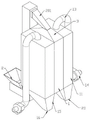
As shown in fig. 1 to 7, the fully automatic powder remover comprises: the device comprises a control circuit, a lifter 2, a separating shell 1 and bag-type dust removing devices symmetrically arranged on two sides of the separating shell 1; at least two collecting hoppers 8 are arranged in the separating shell 1 from top to bottom, a material scattering plate 9 is arranged below the collecting hoppers 8 in the middle, and dust extraction ports 5 are formed in the separating shell 1 on two sides of each collecting hopper 8; the bag-type dust collector is provided with a dust collecting shell 11 connected with the separating shell 1, the dust collecting shell 11 is provided with a dust collecting opening 12 corresponding to the dust suction opening 5, the top of the dust collecting shell 11 is connected with a fan 14 through an induced duct 13, and the bottoms of the two bag-type dust collectors are respectively provided with a first discharger 16 and a second discharger 20; the lifting machine 2 is provided with a discharge pipe 201, the top of the separation shell 1 is provided with a top cover 3, the top cover 3 is provided with a feed inlet 10 connected with the discharge pipe 201, when the lifting machine 2 is used, materials can be conveniently lifted to the top of the separation shell 1, and then the materials are discharged into the feed inlet 10 through the discharge pipe 201 to complete the feeding process of the materials; the control circuit is provided with a controller and a power supply circuit, the hoister 2, the fan 14, the first discharger 16 and the second discharger 20 are all connected with the controller, and a human-computer interface and a control key are connected to the controller; in the embodiment, the powder removing machine is started and stopped through the control key, after the powder removing machine is started, the fan 14 is started firstly, the first discharger 16 and the second discharger 20 are delayed for a period of time, and the elevator 2 starts to operate after the first discharger and the second discharger are delayed for a period of time, so that the automatic control of the powder removing machine is realized, the manual intervention is reduced, the working efficiency of equipment can be improved, and the parameters of the elevator and the fan can be set through a human-computer interface; more specifically, after the fan 14 is started, the fan 14 drives the air inside the dust removing housing 11 to flow outwards to generate negative pressure, and dust inside the separation housing 1 is absorbed from the dust suction port 5 through the dust suction port 12; the mixed material of particles and dust enters from the top of the separation shell 1, the materials are gathered together through the first gathering hopper 8 and then enter the separation shell 1, then the materials are guided to two sides by the first scattering plate 9 to be dispersed, the contact area between air and dust is increased, then the materials are gathered together again through the second gathering hopper 8, and then the materials are dispersed to two sides through the second scattering plate 9; the retention time of the materials in the separation shell 1 can be prolonged through the material collecting hopper 8 and the bulk material plate 9 once, meanwhile, the contact area between the materials and air can be increased, the lifting of dust inside and outside the materials is facilitated, the dust is sucked out of the separation shell through the cloth bag dust removing device, the dust removing effect in the materials can be improved, the separation effect of particles and dust is further improved, meanwhile, the dust can be absorbed and treated in a centralized mode, and the pollution to the environment is avoided; in addition, in the actual use process, the bottoms of the separation shell 1 and the dust removal shell 11 need to be supported by brackets, and the brackets can be made of angle steel by welding.
As a more specific embodiment of the bag-type dust collector, as shown in fig. 4 and 5, a blower 14 is connected to the top of the dust-collecting housing 11 through an induced duct 13, a dust hopper 15 is provided at the bottom of the dust-collecting housing 11, and a first discharger 16 or a second discharger 20 is provided at the bottom of the dust hopper 15; a supporting pattern plate 17 is arranged in the dust removing shell 11, a dust removing cloth bag 19 is assembled on the supporting pattern plate 17, and a back blowing device 19 corresponding to the dust removing cloth bag 19 is erected above the supporting pattern plate 17; after the fan 14 is started, the air in the dust collection shell 11 is driven to flow, the dust in the separation shell 1 is sucked into the dust collection shell 11, the dust is isolated outside the dust collection shell 18 by the dust collection cloth bag 18, after the dust collection is finished, the fan 14 is stopped, the back blowing device 19 is started, reverse airflow is applied to the dust collection cloth bag 18, the dust filtered outside the dust collection cloth bag 18 is blown off, the dust is collected in the dust collection hopper 15 after falling, and finally the discharger 16 is started to discharge the dust in the dust collection hopper 15; the back-blowing device 19 is the prior art, and the specific structure thereof is not described in detail; wherein the discharger 16 is embodied as a star discharger.
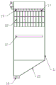
As shown in fig. 2 and 3, a collecting hopper 4 communicated with the separating shell 1 is arranged at the bottom of the separating shell 1, a particle outlet 7 is arranged at the bottom of the collecting hopper 4, the separated particles continuously fall under the action of gravity, enter the collecting hopper 4, are gathered together through the collecting hopper 4 and then are discharged from the particle outlet 7, and the separated particles can be collected below the particle outlet 7. In order to prevent the negative pressure dust removal device from pumping out particles at the dust pumping port 5, a filter plate 6 is arranged on the dust pumping port 5, through holes with the aperture smaller than the diameter of the particles are uniformly formed in the filter plate 6, dust can be sucked out from the separation shell 1 through the filter plate 6, the particles can be prevented from being sucked out, and waste of materials is avoided.
Through holes are uniformly formed in the first board body 901 and the second board body 902, and the through holes formed in the first board body 901 and the second board body 902 are beneficial to air circulation, so that the dust absorption effect is further improved; as a specific embodiment of the material scattering plate 9, an included angle between the first plate 901 and the second plate 902 is 45 ° to 135 °.
As a more specific embodiment of the collecting hopper 8, the collecting hopper 8 has a square funnel structure, and the collecting hopper 8 is formed by a steel plate welding machine and fixed inside the separation housing 1 by welding.
As a more specific embodiment of the environment-friendly particle and powder separating device, three collecting hoppers 8 are arranged inside the separating casing 1 from top to bottom.
As a more specific connection mode of the elevator, as shown in fig. 10, RST ends of frequency converters VF3 are respectively connected to a power supply, UVW ends are connected to a motor M3, an intermediate relay KA3 is connected in series between a DI1 end and a COM end of a frequency converter VF3, an intermediate relay KA3 is connected to an output end Q0.2 of the PLC, when an output of Q0.2 is that the motor M3 is started, the elevator starts to operate, GND ends and AI ends of the frequency converters VF3 and AI ends 2 are respectively connected to 2M ends and 2 ends of an analog quantity module, and control parameters of the frequency converters VF3 can be modified through a man-machine interface; as a more specific connection mode of the fan, as shown in fig. 11, after passing through a breaker QF2, the PST of a frequency converter VF1 is connected to a power supply, the UVW end is connected to a motor M1, an intermediate relay KA1 is connected in series between the FWD end and the COM end of the frequency converter VF1, the intermediate relay KA1 is connected to an output end Q0.0 of the PLC, when the output of Q0.0 is that the motor M1 is started, the fan starts to operate, and the GND end and the AI2 end of the frequency converter VF1 are connected to the 0M end and the 0 end of the analog quantity module respectively, so that control parameters of the frequency converter VF1 can be modified through a man-machine interface; it should be noted that two bag-type dust collectors can share one fan, or two bag-type dust collectors are respectively connected with one fan, and the connection mode of adding one fan is the same as that described above.
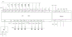
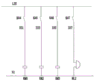
As shown in fig. 7, 9 and 10, as a more specific connection mode of the first discharger, a contactor KM1 is connected to the first discharger, a normally open contact of the contactor KM1 is connected to the first discharger, a coil of the contactor KM1 is connected to an intermediate relay KA4, the intermediate relay KA4 is connected to an output terminal Q0.3 of the PLC, and the first discharger operates when Q0.3 has an output; the first discharger is connected with a contactor KM2, a normally open contact of the contactor KM2 is connected with the second discharger, a coil of the contactor KM2 is connected with an intermediate relay KA5, the intermediate relay KA5 is connected with an output end Q0.4 of the PLC, and the second discharger operates when Q0.4 has output; wherein first tripper, first tripper are the star type tripper.
As shown in fig. 8, the power supply circuit has a transformer from AC380V to AC220V, a power module from AC220V to DC24V is connected to the output of the transformer, and DC24V output by the power module is used to supply power to the intermediate relay.
As shown in fig. 7, the control key has an emergency stop key SB1, a start key SB2, and a stop key SB2, and the emergency stop key SB1, the start key SB2, and the stop key SB2 are connected to the I0.2, I0.3, and I0.4 ends of the PLC, respectively.
In a more specific implementation manner, in the above embodiment, the PLC may be siemens SR20PLC, and the analog module may be EMAQ04 analog module.
The above-mentioned embodiments only represent some embodiments of the present invention, and the description thereof is specific and detailed, but not construed as limiting the scope of the invention. It should be noted that, for those skilled in the art, without departing from the spirit of the present invention, several variations and modifications can be made, which are within the scope of the present invention. Therefore, the protection scope of the present invention should be subject to the appended claims.
Claims (10)
1. A full-automatic powder removing machine is characterized by comprising:
the device comprises a control circuit, a lifter, a separating shell and bag dust removing devices symmetrically arranged on two sides of the separating shell;
at least two collecting hoppers are arranged in the separating shell from top to bottom, a material scattering plate is arranged below the collecting hoppers in the middle, and dust extraction ports are formed in the separating shell on the two sides of each collecting hopper;
the bag-type dust collector is provided with a dust collecting shell connected with the separating shell, the dust collecting shell is provided with a dust collecting opening corresponding to the dust suction opening, the top of the dust collecting shell is connected with a fan through an induced duct, and the bottoms of the two bag-type dust collectors are respectively provided with a first discharger and a second discharger;
the lifting machine is provided with a discharge pipe, the top of the separation shell is provided with a top cover, and the top cover is provided with a feed inlet connected with the discharge pipe;
the control circuit is provided with a controller and a power supply circuit, the hoister, the fan, the first discharger and the second discharger are all connected with the controller, and the controller is connected with a human-computer interface and a control key.
2. The fully automatic powder remover according to claim 1, wherein: the dust collection device is characterized in that a dust collection hopper is arranged at the bottom of the dust collection shell, a supporting pattern plate is arranged in the dust collection shell, a dust collection cloth bag is assembled on the supporting pattern plate, and a back blowing device corresponding to the dust collection cloth bag is erected above the supporting pattern plate.
3. The fully automatic powder remover according to claim 1, wherein: the bottom of the separation shell is provided with a material collecting hopper communicated with the separation shell, and the bottom of the material collecting hopper is provided with a particle outlet.
4. The fully automatic powder remover according to claim 1, wherein: the dust extraction port is provided with a filter plate, and the filter plate is uniformly provided with through holes.
5. The fully automatic powder remover according to claim 1, wherein: the bulk cargo board has symmetrical first plate body and second plate body, first plate body upper end with the upper end of second plate body links into an organic whole structure, evenly set up the through-hole on first plate body and the second plate body.
6. The fully automatic powder remover according to claim 1, wherein: a frequency converter VF3 is connected to the hoisting machine, and the frequency converter VF3 is connected with the controller; the fan is connected with a frequency converter VF1, and the frequency converter VF1 is connected with the controller; the controller is provided with a PLC and an analog quantity module connected with the PLC.
7. The fully automatic powder remover according to claim 6, wherein: an intermediate relay KA3 is connected in series between the DI1 end and the COM end of the frequency converter VF3, the intermediate relay KA3 is connected with the output end of the PLC, and the GND end and the AI2 end of the frequency converter VF3 are respectively connected with the 2M end and the 2 end of the analog quantity module; an intermediate relay KA1 is connected in series between the FWD end and the COM end of the frequency converter VF1, the intermediate relay KA1 is connected with the output end of the PLC, and the GND end and the AI2 end of the frequency converter VF1 are respectively connected with the 0M end and the 0 end of the analog quantity module.
8. The fully automatic powder remover according to claim 6, wherein: a contactor KM1 is connected to the first discharger, a normally open contact of the contactor KM1 is connected to the first discharger, a coil of the contactor KM1 is connected to an intermediate relay KA4, and the intermediate relay KA4 is connected to the output end of the PLC; the second discharger is connected with a contactor KM2, a normally open contact of the contactor KM2 is connected with the second discharger, a coil of the contactor KM2 is connected with an intermediate relay KA5, and the intermediate relay KA5 is connected with the output end of the PLC.
9. The fully automatic powder remover according to claim 2, wherein: the power supply circuit is provided with a transformer from AC380V to AC220V, and the output end of the transformer is connected with a power supply module from AC220V to DC 24V.
10. The fully automatic powder remover according to claim 2, wherein: the control keys are provided with an emergency stop key SB1, a start key SB2 and a stop key SB 2.
Priority Applications (1)
| Application Number | Priority Date | Filing Date | Title |
|---|---|---|---|
| CN202022818513.7U CN213914872U (en) | 2020-11-30 | 2020-11-30 | Full-automatic powder removing machine |
Applications Claiming Priority (1)
| Application Number | Priority Date | Filing Date | Title |
|---|---|---|---|
| CN202022818513.7U CN213914872U (en) | 2020-11-30 | 2020-11-30 | Full-automatic powder removing machine |
Publications (1)
| Publication Number | Publication Date |
|---|---|
| CN213914872U true CN213914872U (en) | 2021-08-10 |
Family
ID=77146000
Family Applications (1)
| Application Number | Title | Priority Date | Filing Date |
|---|---|---|---|
| CN202022818513.7U Expired - Fee Related CN213914872U (en) | 2020-11-30 | 2020-11-30 | Full-automatic powder removing machine |
Country Status (1)
| Country | Link |
|---|---|
| CN (1) | CN213914872U (en) |
-
2020
- 2020-11-30 CN CN202022818513.7U patent/CN213914872U/en not_active Expired - Fee Related
Similar Documents
| Publication | Publication Date | Title |
|---|---|---|
| CN102837863A (en) | Catalyst unpacking and conveying and dust removing system and method for FCC (Fluid Catalytic Cracking) device | |
| CN213914872U (en) | Full-automatic powder removing machine | |
| CN207674588U (en) | A kind of nothing needs to change the air filter of strainer | |
| CN201921875U (en) | Coating powder feeding and dust removal device | |
| CN208194015U (en) | Dust separation device is used in furniture processing | |
| CN206652320U (en) | A kind of High-efficiency pulse cloth bag-type dust collecting equipment | |
| CN203227370U (en) | Filter cylinder type dust collection machine | |
| CN213912768U (en) | Environment-friendly special powder remover | |
| CN211839035U (en) | Intelligent dust removal system | |
| CN101391755B (en) | Sulphuric acid cCatalyst screening method | |
| CN211329873U (en) | Novel agricultural crushing machine matched dust remover group | |
| CN210009786U (en) | Dust removal device for purification air conditioner | |
| CN104772704A (en) | Cyclone grinding dust collection table | |
| CN208617685U (en) | A kind of electrostatic desiccation machine | |
| CN218188720U (en) | Smoke treatment device for fabric shaping equipment | |
| CN206709231U (en) | Intelligent air purification device | |
| CN112007444A (en) | Novel high-efficient sack cleaner and supplementary deashing device thereof | |
| CN214415892U (en) | Dust removing device | |
| CN219683538U (en) | Dust suction device | |
| CN213527952U (en) | Be used for panel raw materials dust filtration processing apparatus | |
| CN211989215U (en) | High-efficient electric poly coupling dust collector | |
| CN215352749U (en) | Waste gas dust remover for mixing of fermentation type mixed feed additive | |
| CN218451963U (en) | Cyclone separator without active power | |
| CN2673508Y (en) | Vertical plate horizontal type electrostatic dust collector | |
| CN201969437U (en) | Energy-saving powerless dust remover for storage bin |
Legal Events
| Date | Code | Title | Description |
|---|---|---|---|
| GR01 | Patent grant | ||
| GR01 | Patent grant | ||
| CF01 | Termination of patent right due to non-payment of annual fee |
Granted publication date: 20210810 |
|
| CF01 | Termination of patent right due to non-payment of annual fee |