CN213902205U - Horizontal tapered roller taper measuring device - Google Patents
Horizontal tapered roller taper measuring device Download PDFInfo
- Publication number
- CN213902205U CN213902205U CN202022916596.3U CN202022916596U CN213902205U CN 213902205 U CN213902205 U CN 213902205U CN 202022916596 U CN202022916596 U CN 202022916596U CN 213902205 U CN213902205 U CN 213902205U
- Authority
- CN
- China
- Prior art keywords
- tapered roller
- face
- tapered
- measuring device
- shaped base
- Prior art date
- Legal status (The legal status is an assumption and is not a legal conclusion. Google has not performed a legal analysis and makes no representation as to the accuracy of the status listed.)
- Active
Links
Images
Abstract
A taper measuring device for a horizontal tapered roller is characterized in that the taper of the tapered roller has convexity; the taper measuring device comprises a V-shaped base, an end face positioning block and two groups of meter frames; two positioning support rods are respectively embedded on the V-shaped surface of the V-shaped base and used for radially positioning the tapered roller and enabling the tapered surface of the tapered roller to be separated from the contact with the V-shaped surface; the end face positioning block is connected to the V-shaped base and is in contact with one end face of the tapered roller and used for positioning the end face of the tapered roller; and the two groups of gauge frames are connected on the V-shaped base, each group of gauge frames is connected with a dial indicator, and measuring rods of the dial indicators are in contact with the conical surfaces of the tapered rollers and used for measuring the conical degrees of the conical surfaces of the tapered rollers at different positions. The utility model realizes the measurement of the conical roller with convexity, and can measure the taper of the conical surface of the conical roller at different positions; the utility model has the advantages of being simple in structure and convenient in operation, can carry out the location measurement to multiple model tapered roller.
Description
Technical Field
The utility model belongs to the technical field of the bearing manufacturing technology and specifically relates to a horizontal tapered roller tapering measuring device is related to.
Background
At present, the amount of taper of the tapered roller is measured by a sine gauge and a D744 measuring instrument. The sinusoidal gauge measuring method has low efficiency and is not suitable for batch measurement in workshops; the D744 measuring instrument has limited measuring range and can only measure the roller with the diameter of less than 70 mm. In order to increase the self-adaptability of the roller, the conical surface of the current tapered roller has a certain convexity, and the two measurement methods can only measure the taper of the tapered roller without the convexity, so that a taper measurement device capable of detecting the tapered roller with the convexity is needed.
SUMMERY OF THE UTILITY MODEL
In order to overcome the not enough in the background art, the utility model discloses a horizontal tapered roller tapering measuring device adopts following technical scheme:
a horizontal tapered roller taper measuring apparatus, a tapered surface of the tapered roller having a convexity, the taper measuring apparatus comprising:
the V-shaped surface of the V-shaped base is respectively embedded with two positioning support rods, and the positioning support rods are used for radial positioning of the tapered roller and make the tapered surface of the tapered roller separate from contact with the V-shaped surface;
the end face positioning block is connected to the V-shaped base, is contacted with one end face of the tapered roller and is used for positioning the end face of the tapered roller;
and the two groups of gauge frames are connected to the V-shaped base, each group of gauge frames is connected with a dial indicator, and measuring rods of the dial indicators are in contact with the conical surfaces of the tapered rollers and used for measuring the conical degrees of the conical surfaces of the tapered rollers at different positions.
According to the technical scheme, the included angle of the V-shaped surface of the V-shaped base is 60-120 degrees.
The technical scheme is further improved, and the positioning support rod is made of hard alloy.
According to the technical scheme, the dial indicator is further improved, the dial indicator frame is provided with a connecting groove, the dial indicator frame is connected with the V-shaped base through a screw and the connecting groove, and the connecting groove is used for adjusting the measuring position of the dial indicator, so that the measuring rod of the dial indicator is arranged along the radial direction of the tapered roller.
The technical scheme is further improved, and steel balls are embedded in the contact parts of the end face positioning blocks and the end faces of the tapered rollers.
According to the technical scheme, the end face positioning block is provided with an adjusting groove, the end face positioning block is connected with the V-shaped base through a screw and the adjusting groove, and the adjusting groove is used for adjusting the positioning position of the end face positioning block.
Owing to adopt above-mentioned technical scheme, compare the background art, the utility model discloses following beneficial effect has:
the utility model realizes the measurement of the conical roller with convexity, and can measure the taper of the conical surface of the conical roller at different positions; the utility model has the advantages of being simple in structure and convenient in operation, can carry out the location measurement to multiple model tapered roller.
Drawings
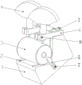
Fig. 1 is a schematic structural diagram of the present invention.
In the figure: 1. a V-shaped base; 2. positioning the support rod; 3. a tapered roller; 4. a dial indicator; 5. an end face positioning block; 6. a watch frame; 7. a screw; 8. watch frame screw.
Detailed Description
Preferred embodiments of the present invention will be described below with reference to the accompanying drawings. It should be understood by those skilled in the art that these embodiments are only for explaining the technical principle of the present invention, and are not intended to limit the scope of the present invention.
A tapered roller has a tapered surface with a constant convexity. In order to realize the detection of the taper, the following taper measuring device is adopted:
as shown in fig. 1, the taper measuring device includes a V-shaped base 1, an end face positioning block 5, and two sets of gauge stands 6. The V-shaped base 1 is a block-shaped body, in order to stabilize the tapered roller 3, the V-shaped surface of the V-shaped base 1 is arranged upwards, and the included angle of the V-shaped surface is 90 degrees. Since the tapered surface of the tapered roller 3 has convexity, it is not possible to directly position it radially using the V-profile. In order to realize the radial positioning of the tapered roller 3, two parallel positioning support rods 2 are respectively embedded on the V-shaped surface of the V-shaped base 1, and the positioning support rods 2 are used for the radial positioning of the tapered roller 3 and enabling the conical surface of the tapered roller 3 to be separated from the contact with the V-shaped surface. In order to improve the wear resistance of the positioning support rod 2, the positioning support rod 2 is made of hard alloy. The end face positioning block 5 is connected to one side face of the V-shaped base 1, and the end face positioning block 5 is in contact with one end face of the tapered roller 3 and used for positioning the end face of the tapered roller 3. In order to improve the positioning accuracy, a steel ball (not shown in the figure) is embedded in a contact part of the end face positioning block 5 and the end face of the tapered roller 3, and the end face positioning block 5 is in contact with the end face of the tapered roller 3 through the steel ball. Up to this point, the tapered roller 3 has been restricted in the remaining degrees of freedom, in addition to the degree of freedom of rotation in the axial direction.
Two sets of meter racks 6 are attached to the top surface of the V-shaped base 1, which is parallel to one of the V-profiles. One end of each group of gauge stand 6 is fixed with a dial indicator 4 through a gauge stand screw 8, and a measuring rod of the dial indicator 4 is in contact with the conical surface of the tapered roller 3 and is used for measuring the conical degree of the conical surface of the tapered roller 3 at different positions. In order to realize the measurement of the tapered rollers 3 of various models, a connecting groove is arranged on the gauge stand 6, the gauge stand 6 is connected with the V-shaped base 1 through a screw 7 and the connecting groove, and the connecting groove is used for adjusting the measuring position of the dial indicator 4, so that the measuring rod of the dial indicator 4 is always arranged along the radial direction of the tapered rollers 3. Similarly, an adjusting groove is arranged on the end face positioning block 5, the end face positioning block 5 is connected with the V-shaped base 1 through a screw 7 and the adjusting groove, and the adjusting groove is used for adjusting the positioning position of the end face positioning block 5, so that the steel ball always abuts against the appropriate position on the end face of the tapered roller 3.
During measurement, the conical surface of the tapered roller 3 is placed on the V-shaped surface, the four positioning support rods 2 are respectively contacted with the left end and the right end of the conical surface of the tapered roller 3, the tapered roller 3 is pushed to enable one end face of the tapered roller to be contacted with the steel ball on the end face positioning block 5, then the tapered roller 3 is rotated, and the conicity of the conical surface of the tapered roller 3 at different positions is measured. Before measurement, the taper of one standard tapered roller 3 is measured, the indexes of the two dial indicators 4 are used as standard values, then the tapered roller 3 to be measured is placed on the standard tapered roller for measurement, the indexes of the two dial indicators 4 are observed and recorded, and whether the indexes are within an allowed tolerance range is judged to judge whether the tapered roller is qualified.
The part of the utility model not detailed is prior art. Although embodiments of the present invention have been shown and described, it will be appreciated by those skilled in the art that changes, modifications, substitutions and alterations can be made in these embodiments without departing from the principles and spirit of the invention, the scope of which is defined in the appended claims and their equivalents.
Claims (6)
1. The utility model provides a horizontal tapered roller tapering measuring device, the conical surface of tapered roller has the convexity, characterized by: the taper measuring device comprises:
the V-shaped surface of the V-shaped base is respectively embedded with two positioning support rods, and the positioning support rods are used for radial positioning of the tapered roller and make the tapered surface of the tapered roller separate from contact with the V-shaped surface;
the end face positioning block is connected to the V-shaped base, is contacted with one end face of the tapered roller and is used for positioning the end face of the tapered roller;
and the two groups of gauge frames are connected to the V-shaped base, each group of gauge frames is connected with a dial indicator, and measuring rods of the dial indicators are in contact with the conical surfaces of the tapered rollers and used for measuring the conical degrees of the conical surfaces of the tapered rollers at different positions.
2. The horizontal tapered roller taper measuring device according to claim 1, wherein: the included angle of the V-shaped surface of the V-shaped base is 60-120 degrees.
3. The horizontal tapered roller taper measuring device according to claim 1 or 2, characterized in that: the positioning support rod is made of hard alloy.
4. The horizontal tapered roller taper measuring device according to claim 1, wherein: the dial gauge is characterized in that the gauge stand is provided with a connecting groove, the gauge stand is connected with the V-shaped base through a screw and the connecting groove, and the connecting groove is used for adjusting the measuring position of the dial gauge so that the measuring rod of the dial gauge is arranged along the radial direction of the tapered roller.
5. The horizontal tapered roller taper measuring device according to claim 1, wherein: and steel balls are embedded in the contact positions of the end face positioning blocks and the end faces of the tapered rollers.
6. The horizontal tapered roller taper measuring device according to claim 1 or 5, wherein: the end face positioning block is provided with an adjusting groove, the end face positioning block is connected with the V-shaped base through a screw and the adjusting groove, and the adjusting groove is used for adjusting the positioning position of the end face positioning block.
Priority Applications (1)
| Application Number | Priority Date | Filing Date | Title |
|---|---|---|---|
| CN202022916596.3U CN213902205U (en) | 2020-12-08 | 2020-12-08 | Horizontal tapered roller taper measuring device |
Applications Claiming Priority (1)
| Application Number | Priority Date | Filing Date | Title |
|---|---|---|---|
| CN202022916596.3U CN213902205U (en) | 2020-12-08 | 2020-12-08 | Horizontal tapered roller taper measuring device |
Publications (1)
| Publication Number | Publication Date |
|---|---|
| CN213902205U true CN213902205U (en) | 2021-08-06 |
Family
ID=77101588
Family Applications (1)
| Application Number | Title | Priority Date | Filing Date |
|---|---|---|---|
| CN202022916596.3U Active CN213902205U (en) | 2020-12-08 | 2020-12-08 | Horizontal tapered roller taper measuring device |
Country Status (1)
| Country | Link |
|---|---|
| CN (1) | CN213902205U (en) |
-
2020
- 2020-12-08 CN CN202022916596.3U patent/CN213902205U/en active Active
Similar Documents
| Publication | Publication Date | Title |
|---|---|---|
| CN202119378U (en) | Steering gear nut internal thread raceway external circle coaxiality testing fixture | |
| CN207132827U (en) | A kind of bearing roller detection means | |
| CN102322779B (en) | Measuring device for angular contact ball bearing outer ring hold depth and measuring method thereof | |
| CN202216637U (en) | Arc section radium fast-measuring tool | |
| CN101799267A (en) | Device and method for measuring symmetry of spindle keyways | |
| CN201593964U (en) | Diameter measuring device of axle part | |
| CN204535603U (en) | Hub bearing outer ring groove position pick-up unit | |
| CN104776779B (en) | Hub bearing outer ring groove position detection means | |
| CN213902205U (en) | Horizontal tapered roller taper measuring device | |
| CN203572358U (en) | Multifunctional comprehensive detecting tool | |
| CN213902307U (en) | Vertical tapered roller taper measuring device | |
| CN201697599U (en) | Tool for detecting the concentricity of spherical path of starlike inner race and spherical surface | |
| CN204831238U (en) | Measure measuring tool that many wedges belt pulley is radial and axial is beated | |
| CN104596383A (en) | Multifunctional comprehensive detecting tool and method | |
| CN102607379A (en) | Detection method of included angle deviations of V-shaped roller paths of inner ring relative to reference end surface | |
| CN203464878U (en) | Hub measuring snap-gauge | |
| CN203116686U (en) | Verticality gauge | |
| CN202661012U (en) | Outer spherical diameter and profile measuring instrument | |
| CN207741680U (en) | A kind of spherical roller detection device | |
| CN105180857A (en) | Measuring tool and method for measuring radial and axial runout of multi-wedge belt pulley | |
| CN103383234A (en) | Device for measuring parallelism of guide rail swallow tail surface | |
| CN201535661U (en) | Special gauge for gauging engine cylinder hole perpendicularity | |
| CN201593965U (en) | Calibrating tool for axle type part diameter measuring device | |
| CN209840906U (en) | On-line detection device for height of supporting shoulder of middle supporting cylinder sleeve | |
| CN210135857U (en) | Detection and measurement device for threaded joint |
Legal Events
| Date | Code | Title | Description |
|---|---|---|---|
| GR01 | Patent grant | ||
| GR01 | Patent grant |