CN213885460U - Waste gas treatment device - Google Patents
Waste gas treatment device Download PDFInfo
- Publication number
- CN213885460U CN213885460U CN202022361255.4U CN202022361255U CN213885460U CN 213885460 U CN213885460 U CN 213885460U CN 202022361255 U CN202022361255 U CN 202022361255U CN 213885460 U CN213885460 U CN 213885460U
- Authority
- CN
- China
- Prior art keywords
- fixed
- rocker
- plate
- water
- treatment device
- Prior art date
- Legal status (The legal status is an assumption and is not a legal conclusion. Google has not performed a legal analysis and makes no representation as to the accuracy of the status listed.)
- Active
Links
Images


Landscapes
- Treating Waste Gases (AREA)
Abstract
The utility model discloses a waste gas treatment device, including base, fixed plate, mounting panel and wastewater collection box, be fixed with the water tank on the base, and seted up the water filling port on the water tank to the water tank internal fixation has the intake pipe, intake pipe left end and air exhauster interconnect simultaneously, cooling plate and pivot interconnect, and be provided with the movable rod in the pivot to the movable rod passes through column axis and rocker interconnect, all is fixed with the magnetite in rocker and the pivot simultaneously, the rocker end is fixed with the pull ring, the mounting panel is fixed in the pivot, and is fixed with clean brush on the mounting panel, wastewater collection box sets up and is handling the incasement. This exhaust treatment device adopts the waste gas waste heat to heat the water and produce steam and adsorb the dust in the waste gas, and cooperation cooling device can make dust water droplet aggregate and collect in falling into the waste water collecting box, reduces water resource loss, and cooling structure can be dismantled in the cooperation, realizes the clearance to the fixed plate, and the assurance device can long-term steady operation.
Description
Technical Field
The utility model relates to a waste gas treatment technical field specifically is a waste gas treatment device.
Background
Waste gas treatment refers to that waste gas generated in industrial places and workshops is pretreated before being discharged to the outside, and the treated waste gas can reach the national standard, so that the pollution problem to the environment is reduced, and the effect of protecting the environment is achieved.
Along with the development of industrialization in China, the demand for steel is more and more, a large amount of coal is generally needed for melting and processing the steel in the production of the steel, the coal can generate a large amount of waste gas with dust and carbon dioxide in the combustion process, and the dust and the carbon dioxide can pollute human bodies and the environment, so the waste gas can be discharged after being treated.
And current device to this type of exhaust-gas treatment mainly adopts the water smoke to spray and removes dust and purifies, and this kind of device exists that the water waste is serious, inconvenient waste gas waste heat that utilizes causes the energy extravagant and to the inconvenient scheduling problem of clearing up of filter equipment, so need improve traditional exhaust-gas treatment device to above-mentioned problem.
Disclosure of Invention
An object of the utility model is to provide a waste gas treatment device to it is serious, inconvenient waste gas waste heat and inconvenient cleaning device's problem to propose the water waste in the above-mentioned background art to solve.
In order to achieve the above object, the utility model provides a following technical scheme: a waste gas treatment device comprises a base, a fixed plate, a mounting plate and a waste water collecting box, wherein a water tank is fixed on the base, a water filling port is formed in the water tank, an air inlet pipe is fixed in the water tank, the left end of the air inlet pipe is connected with an exhaust fan, the right end of the air inlet pipe is connected with a treatment box, the treatment box is connected with the water tank, the treatment box is fixed on the base, an active carbon layer is fixed in the treatment box, an absorption layer is fixed in the treatment box, the fixed plate is connected with the treatment box, a handle is fixed at the upper end of the fixed plate, sealing rubber is fixed on the fixed plate, a cooling plate is fixed on the fixed plate, the cooling plate is connected with a rotating shaft, a movable rod is arranged in the rotating shaft, the movable rod is connected with a rocker through a column shaft, magnets are fixed on the rocker and the rotating shaft, and a pull ring is fixed at the tail end of the rocker, the mounting panel is fixed in the pivot, and is fixed with clean brush on the mounting panel, waste water collecting box sets up in handling the incasement.
Preferably, the air inlet pipe is made of aluminum alloy and is of a rotary U-shaped structure.
Preferably, the activated carbon layer, the absorption layer and the fixing plate are distributed from right to left, and the absorption layer is internally provided with sodium hydroxide particles.
Preferably, the fixed plate is connected with the processing box in a sliding mode, and the fixed plate is connected with the processing box in a clamping mode through sealing rubber.
Preferably, the movable rod forms a rotating structure through the column shaft and the rocker, the movable rod is of a T-shaped structure, and the length of the movable rod and the length of the rocker are equal to the length of the hole in the rotating shaft.
Preferably, the mounting plate and the cleaning brushes are concentrically distributed about the central point of the rotating shaft, and the mounting plate and the cleaning brushes are symmetrically distributed about the fixing plate.
Compared with the prior art, the beneficial effects of the utility model are that: this exhaust treatment device adopts the waste gas waste heat to heat the water and produce steam and adsorb the dust in the waste gas, and cooperation cooling device can make dust water droplet aggregate and collect in falling into the waste water collecting box, reduces water resource loss, and cooling structure can be dismantled in the cooperation, realizes the clearance to the fixed plate, and the assurance device can long-term steady operation.
1. In with waste gas suction inlet pipe through the air exhauster, the effect of cooperation water tank and intake pipe can prolong waste gas time in the inlet pipe to make the water can fast the heat absorption produce the dust that the great amount of vapor is used for adsorbing in the waste gas in the water tank, thereby realize the processing to the dust.
2. The fixed plate can be taken out in the effect of pulling handle, cooperation sealing rubber, and the effect of pull ring, rocker, movable rod, pivot, mounting panel and clean brush can be taken out whole cooling device and clear up again, guarantees the clean and tidy of device, improves the life of device.
Drawings
FIG. 1 is a schematic view of the front view structure of the base of the present invention;
FIG. 2 is a schematic side view of the fixing plate of the present invention;
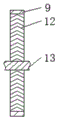
FIG. 3 is a schematic view of the front sectional structure of the rotating shaft of the present invention;
FIG. 4 is a schematic view of the front view structure of the rotating shaft of the present invention;
fig. 5 is a schematic view of the front cross-section of the fixing plate of the present invention.
In the figure: 1. a base; 2. a water tank; 3. a water injection port; 4. an air inlet pipe; 5. an exhaust fan; 6. a treatment tank; 7. an activated carbon layer; 8. an absorbing layer; 9. a fixing plate; 10. a handle; 11. sealing rubber; 12. a cooling plate; 13. a rotating shaft; 14. a movable rod; 15. a rocker; 16. a magnet; 17. a pull ring; 18. mounting a plate; 19. cleaning the brush; 20. a waste water collecting tank.
Detailed Description
The technical solutions in the embodiments of the present invention will be described clearly and completely with reference to the accompanying drawings in the embodiments of the present invention, and it is obvious that the described embodiments are only some embodiments of the present invention, not all embodiments. Based on the embodiments in the present invention, all other embodiments obtained by a person skilled in the art without creative work belong to the protection scope of the present invention.
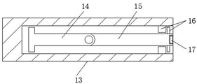
Referring to fig. 1-5, the present invention provides a technical solution: a waste gas treatment device comprises a base 1, a water tank 2, a water filling port 3, an air inlet pipe 4, an exhaust fan 5, a treatment box 6, an activated carbon layer 7, an absorption layer 8, a fixing plate 9, a handle 10, sealing rubber 11, a cooling plate 12, a rotating shaft 13, a movable rod 14, a rocker 15, a magnet 16, a pull ring 17, a mounting plate 18, a cleaning brush 19 and a waste water collecting box 20, wherein the water tank 2 is fixed on the base 1, the water filling port 3 is arranged on the water tank 2, the air inlet pipe 4 is fixed in the water tank 2, the left end of the air inlet pipe 4 is connected with the exhaust fan 5, the right end of the air inlet pipe 4 is connected with the treatment box 6, the treatment box 6 is connected with the water tank 2, the treatment box 6 is fixed on the base 1, the activated carbon layer 7 is fixed in the treatment box 6, the absorption layer 8 is fixed in the treatment box 6, the fixing plate 9 is connected with the treatment box 6, the handle 10 is fixed at the upper end of the fixing plate 9, and be fixed with sealing rubber 11 on the fixed plate 9, be fixed with cooling plate 12 on the fixed plate 9 simultaneously, cooling plate 12 and pivot 13 interconnect, and be provided with movable rod 14 in the pivot 13 to movable rod 14 passes through the column axis and rocker 15 interconnect, all is fixed with magnetite 16 on rocker 15 and the pivot 13 simultaneously, and the rocker 15 end is fixed with pull ring 17, and mounting panel 18 is fixed on pivot 13, and is fixed with cleaning brush 19 on the mounting panel 18, and waste water collecting box 20 sets up in handling the case 6.
The material of intake pipe 4 is the aluminum alloy, and intake pipe 4 is for circling round "U" type structure, guarantees at air exhauster 5 with back in exhaust gas suction intake pipe 4, waste gas can carry out enough long-time flow in intake pipe 4 to make the waste gas waste heat can fully be absorbed steam by the water in the water tank 2, so that the back can effectively clear away the dust, and the aluminum alloy material has higher corrosion resistance, can guarantee the life of device.
Activated carbon layer 7, absorbed layer 8 and fixed plate 9 are for following the right side to left side distribution, and are provided with the material in the absorbed layer 8 and be the sodium hydroxide granule, after the dust is handled, can effectively absorb the carbon dioxide in the waste gas through the effect of absorbed layer 8, reduce the emission of carbon dioxide to the peculiar smell in the waste gas can effectively be clear away through the effect on activated carbon layer 7, the assurance is to the processing quality requirement of waste gas.
Fixed plate 9 and handle and be sliding connection between the case 6, and fixed plate 9 constitutes the block through sealing rubber 11 and handle case 6 and is connected, through pulling handle 10, cooperates fixed plate 9 and handle the sliding connection between the case 6, conveniently takes out fixed plate 9 and clears up, during the installation, through sealing rubber 11's effect, can effectively prevent that gas is excessive.
The movable rod 14 passes through the column axis and constitutes revolution mechanic with rocker 15, and the movable rod 14 is "T" type structure, and the length of movable rod 14 and rocker 15 equals the length of trompil on the pivot 13, through pulling pull ring 17, thereby can take movable rod 14 and rocker 15 out in the pivot 13, and rocker 15 can rotate around movable rod 14, cooperation pivot 13 forms the rocking wheel structure, conveniently provides power for pivot 13, thereby provides the power basis for mounting panel 18 and cleaning brush 19.
The mounting plate 18 and the cleaning brushes 19 are concentrically distributed about the central point of the rotating shaft 13, the mounting plate 18 and the cleaning brushes 19 are symmetrically distributed about the fixed plate 9, and the mounting plate 18 and the cleaning brushes 19 can be driven to rotate under the action of the rotating shaft 13, the movable rod 14 and the rocker 15, so that the cleaning of the cleaning brushes 19 on the fixed plate 9 and the cooling plate 12 is ensured, and the cleaning of the fixed plate 9 and the cooling plate 12 is more convenient and simpler.
The working principle is as follows: when the waste gas treatment device is used, firstly, the whole device is placed near a waste gas outlet through a base 1, an air inlet pipe 4 is connected with the waste gas outlet of a coal burning device, cooling water is injected into a water tank 2 through a water injection port 3, an exhaust fan 5 is started, high-temperature waste gas enters the air inlet pipe 4 under the action of the exhaust fan 5, the cooling water of the water tank 2 absorbs heat through the outer wall of the air inlet pipe 4, the waste gas needs to flow for a long enough time due to the U-shaped structure of the air inlet pipe 4, a large amount of steam generated by heat absorption of the cooling water of the water tank 2 enters a treatment box 6, the waste gas enters the treatment box 6 through the air inlet pipe 4, dust in the waste gas is adsorbed by the steam and moves rightwards, the steam passes through a fixing plate 9 and a cooling plate 12 to be cooled and condensed, and the condensed steam drops into a waste water collecting box 20 due to the inverted V-shaped structure of the cooling plate 12, therefore, dust in the exhaust gas is removed, the exhaust gas continuously moves to the right, the exhaust gas respectively passes through the absorption layer 8 and the activated carbon layer 7, carbon dioxide in the exhaust gas is absorbed under the action of the absorption layer 8, peculiar smell in the exhaust gas is absorbed through the action of the activated carbon layer 7, the exhaust gas is treated, and the treated exhaust gas is discharged from an opening in the treatment box 6, as shown in fig. 1;
after long-time use, the sewage in the wastewater collection tank 20 needs to be cleaned, and because the cooling plate 12 is adsorbed with water drops with dust for a long time, adhesion is easily formed, the cleaning needs to be carried out, the fixed plate 9 is taken out only by pulling the handle 10, the pull ring 17 is pulled, the movable rod 14 and the rocker 15 are pulled out, the rocker 15 rotates around the movable rod 14, the rotating shaft 13, the movable rod 14 and the rocker 15 form a rocking wheel structure, the rocker 15 is rotated to drive the rotating shaft 13 to rotate, the mounting plate 18 and the cleaning brush 19 are driven to rotate, the cleaning brush 19 cleans the fixed plate 9 and the cooling plate 12, the operation is convenient and simple, after cleaning, the movable rod 14 and the rocker 15 are pushed into the rotating shaft 13 to be fixed through the action of the magnet 16, the fixed plate 9 is convenient to be mounted, the fixed plate 9 is mounted in the processing tank 6 according to the principle, the outflow of gas in the treatment tank 6 can be prevented by the action of the sealing rubber 11, and the sealing effect is ensured, as shown in fig. 2, 3 and 4, which is the working principle of the exhaust gas treatment device.
Although embodiments of the present invention have been shown and described, it will be appreciated by those skilled in the art that changes, modifications, substitutions and alterations can be made in these embodiments without departing from the principles and spirit of the invention, the scope of which is defined in the appended claims and their equivalents.
Claims (6)
1. The utility model provides an exhaust treatment device, includes base (1), fixed plate (9), mounting panel (18) and waste water collection box (20), its characterized in that: the water treatment device is characterized in that a water tank (2) is fixed on the base (1), a water filling port (3) is formed in the water tank (2), an air inlet pipe (4) is fixed in the water tank (2), the left end of the air inlet pipe (4) is connected with an exhaust fan (5), the right end of the air inlet pipe (4) is connected with a treatment box (6), the treatment box (6) is connected with the water tank (2), the treatment box (6) is fixed on the base (1), an activated carbon layer (7) is fixed in the treatment box (6), an absorption layer (8) is fixed in the treatment box (6), a fixing plate (9) is connected with the treatment box (6), a handle (10) is fixed at the upper end of the fixing plate (9), sealing rubber (11) is fixed on the fixing plate (9), a cooling plate (12) is fixed on the fixing plate (9), and the cooling plate (12) is connected with a rotating shaft (13), and be provided with movable rod (14) in pivot (13) to movable rod (14) all are fixed with magnetite (16) through column axis and rocker (15) interconnect simultaneously on rocker (15) and pivot (13), rocker (15) end is fixed with pull ring (17), mounting panel (18) are fixed on pivot (13), and are fixed with cleaning brush (19) on mounting panel (18), wastewater collection box (20) set up in handling case (6).
2. An exhaust gas treatment device according to claim 1, wherein: the air inlet pipe (4) is made of aluminum alloy, and the air inlet pipe (4) is of a rotary U-shaped structure.
3. An exhaust gas treatment device according to claim 1, wherein: the activated carbon layer (7), the absorption layer (8) and the fixing plate (9) are distributed from right to left, and the absorption layer (8) is internally provided with sodium hydroxide particles.
4. An exhaust gas treatment device according to claim 1, wherein: the fixed plate (9) is in sliding connection with the treatment box (6), and the fixed plate (9) is in clamping connection with the treatment box (6) through sealing rubber (11).
5. An exhaust gas treatment device according to claim 1, wherein: the movable rod (14) and the rocker (15) form a rotating structure through a column shaft, the movable rod (14) is of a T-shaped structure, and the length of the movable rod (14) and the length of the rocker (15) are equal to the length of the opening in the rotating shaft (13).
6. An exhaust gas treatment device according to claim 1, wherein: the mounting plate (18) and the cleaning brushes (19) are concentrically distributed about the central point of the rotating shaft (13), and the mounting plate (18) and the cleaning brushes (19) are symmetrically distributed about the fixing plate (9).
Priority Applications (1)
| Application Number | Priority Date | Filing Date | Title |
|---|---|---|---|
| CN202022361255.4U CN213885460U (en) | 2020-10-21 | 2020-10-21 | Waste gas treatment device |
Applications Claiming Priority (1)
| Application Number | Priority Date | Filing Date | Title |
|---|---|---|---|
| CN202022361255.4U CN213885460U (en) | 2020-10-21 | 2020-10-21 | Waste gas treatment device |
Publications (1)
| Publication Number | Publication Date |
|---|---|
| CN213885460U true CN213885460U (en) | 2021-08-06 |
Family
ID=77113859
Family Applications (1)
| Application Number | Title | Priority Date | Filing Date |
|---|---|---|---|
| CN202022361255.4U Active CN213885460U (en) | 2020-10-21 | 2020-10-21 | Waste gas treatment device |
Country Status (1)
| Country | Link |
|---|---|
| CN (1) | CN213885460U (en) |
-
2020
- 2020-10-21 CN CN202022361255.4U patent/CN213885460U/en active Active
Similar Documents
| Publication | Publication Date | Title |
|---|---|---|
| CN207950949U (en) | A kind of energy-saving, environmental protection boiler emission-control equipment | |
| CN212166837U (en) | Filter equipment for nitrogen generator | |
| CN109248550A (en) | A kind of clean seal formula boiler flue gas desulfurization denitrification apparatus with filtering function | |
| CN220572947U (en) | Catalytic exhaust gas treatment device for exhaust gas treatment | |
| CN206593488U (en) | One kind energy-conservation smelting iron and steel waste gas dedusting case | |
| CN209362171U (en) | A kind of waste gas purification wash mill of environmental protection | |
| CN213885460U (en) | Waste gas treatment device | |
| CN219290999U (en) | Waste gas pollution treatment device | |
| CN111298615A (en) | Leading SDS desulphurization unit of msw incineration flue gas | |
| CN212680582U (en) | Energy-saving municipal domestic waste is exhaust treatment device for carbonization | |
| CN206853331U (en) | Dust removal device for powdered ink production | |
| CN216024067U (en) | Flow-adjustable flue gas denitration device | |
| CN211358243U (en) | Workshop exhaust gas purification device | |
| CN213398216U (en) | Power plant waste gas detection device convenient to detect | |
| CN210934367U (en) | Waste gas collecting device for stacking solid garbage | |
| CN210718784U (en) | Waste heat recovery device for exhaust-gas treatment | |
| CN218833887U (en) | Kitchen meal waste gas purification device | |
| CN215462992U (en) | Waste incineration plant peculiar smell gas centralized treatment device | |
| CN101322893A (en) | Smoke cyclic screening and dedusting method and apparatus | |
| CN219481954U (en) | Flue gas recovery device for graphitization furnace | |
| CN219197436U (en) | Smoke removing device of diesel generating set | |
| CN113959231B (en) | Tin smelting electric furnace tail gas treatment and waste heat utilization device | |
| CN214182513U (en) | Low-energy-consumption industrial desulfurization dust removal equipment | |
| CN216591778U (en) | Waste heat utilization device for energy conservation of power plant | |
| CN221207399U (en) | Improved smoke dust purifying device of laser cutting machine |
Legal Events
| Date | Code | Title | Description |
|---|---|---|---|
| GR01 | Patent grant | ||
| GR01 | Patent grant |