CN213817242U - Direct current power supply device and transformation rectification power supply system - Google Patents
Direct current power supply device and transformation rectification power supply system Download PDFInfo
- Publication number
- CN213817242U CN213817242U CN202022464606.4U CN202022464606U CN213817242U CN 213817242 U CN213817242 U CN 213817242U CN 202022464606 U CN202022464606 U CN 202022464606U CN 213817242 U CN213817242 U CN 213817242U
- Authority
- CN
- China
- Prior art keywords
- rectifier
- power supply
- isolation chamber
- cabinet
- isolation
- Prior art date
- Legal status (The legal status is an assumption and is not a legal conclusion. Google has not performed a legal analysis and makes no representation as to the accuracy of the status listed.)
- Active
Links
Images


Landscapes
- Rectifiers (AREA)
Abstract
The utility model belongs to the technical field of the DC supply equipment, a DC supply device and vary voltage rectification power supply system is related to. This dc power supply device includes the rectifier cabinet, and the rectifier cabinet includes: a housing; an alternating current incoming cable; the alternating current circuit breaker is electrically connected with the alternating current incoming cable; a rectifier group electrically connected to the AC circuit breaker; the direct-current bus is electrically connected with the rectifier group; the short-circuit protection electric appliance is electrically connected with the direct-current busbar; and the direct current load end is electrically connected with the short-circuit protection electrical appliance. The alternating current circuit breaker is located in the first isolation chamber, the rectifier group is located in the second isolation chamber, at least one part of the direct current busbar is located in the third isolation chamber, the short-circuit protection electric appliance is located in the fourth isolation chamber, and at least part of partition plates of the first isolation chamber, the second isolation chamber, the third isolation chamber and the fourth isolation chamber are made of conductive materials and are grounded. This direct current power supply unit can improve security and maintenance convenience through carrying out physical isolation with different functional unit.
Description
Technical Field
The utility model belongs to the technical field of the DC supply equipment, a DC supply device and vary voltage rectification power supply system is related to.
Background
With the rapid development of information technology, data centers are more and more widely applied. The components of the data center generally need a dc power supply to operate, and the power of the data center is generally large. At present, a power supply of a data center converts medium-voltage or high-voltage alternating current into low-voltage alternating current through an alternating current transformer, and the low-voltage alternating current is converted into direct current through a rectifier after passing through a low-voltage incoming switch and is output. The existing direct-current power supply cabinet has the problems of low safety, difficult maintenance and the like.
SUMMERY OF THE UTILITY MODEL
An embodiment of the utility model provides a DC power supply device and vary voltage rectification power supply system. This dc power supply device includes the rectifier cabinet, the rectifier cabinet includes: a housing; an alternating current incoming cable; the alternating current circuit breaker is electrically connected with the alternating current incoming cable; a rectifier group electrically connected to the ac circuit breaker; the direct-current bus is electrically connected with the rectifier group; the short-circuit protection electric appliance is electrically connected with the direct-current busbar; and the direct current load end is electrically connected with the short-circuit protection electrical appliance. The alternating current circuit breaker is located first isolation chamber, the rectifier group is located the second isolation chamber, female at least partly that arranges of direct current is located the third isolation chamber, short-circuit protection electrical apparatus is located the fourth isolation chamber, first isolation chamber the second isolation chamber the third isolation chamber with at least part baffle of fourth isolation chamber is made by can conducting material and ground connection. This rectifier cabinet can improve security and maintenance convenience through carrying out physical isolation with different functional unit.
An embodiment of the utility model provides a DC power supply device, including the rectifier cabinet, the rectifier cabinet includes: a housing; an alternating current incoming cable configured to access alternating current; the alternating current circuit breaker is positioned in the shell and comprises a first end and a second end, and the alternating current incoming cable penetrates through the shell and is electrically connected with the first end of the alternating current circuit breaker; a rectifier set positioned within the housing and including an ac input and a dc output, the ac input of the rectifier set electrically connected to the second end of the ac circuit breaker, the rectifier set configured to convert ac power to dc power; the direct-current bus is positioned in the shell and is electrically connected with a direct-current output end of the rectifier group; the short-circuit protection electric appliance is positioned in the shell and comprises a first end and a second end, and the first end of the short-circuit protection electric appliance is electrically connected with the direct-current bus; and a dc load end located in the housing, the dc load end electrically connected to the second end of the short-circuit protection device and configured to output dc power, wherein the ac circuit breaker is located in the first isolation chamber, the rectifier set is located in the second isolation chamber, at least a part of the dc bus bar is located in the third isolation chamber, the short-circuit protection device is located in the fourth isolation chamber, and at least a part of the partition plates of the first isolation chamber, the second isolation chamber, the third isolation chamber and the fourth isolation chamber are made of conductive materials and grounded.
In some examples, the third isolation chamber is located on a side of the second isolation chamber distal from the first isolation chamber, and the fourth isolation chamber is located on a side of the third isolation chamber distal from the second isolation chamber.
In some examples, the first isolation chamber, the second isolation chamber, the third isolation chamber, and the fourth isolation chamber are removably mounted within the housing.
In some examples, the number of the rectifier groups is multiple, the direct current output ends of the plurality of rectifier groups are electrically connected with the direct current busbar, and each rectifier group comprises at least one rectifier.
In some examples, the number of the ac breakers is plural, and the plural ac breakers are electrically connected to the plural rectifier groups in a one-to-one correspondence.
In some examples, the housing includes a first door panel and a second door panel that are opposite to each other in a first direction, the first door panel includes a first air outlet, an air inlet, and a second air outlet that are sequentially arranged in a second direction, the second door panel includes a third air outlet, a fourth air outlet, and a fifth air outlet that are sequentially arranged in the second direction, the second direction forms an angle with the first direction, and a fan is further disposed in the rectifier group and configured to suck air from the air inlet and discharge the air from the first air outlet, the second air outlet, the third air outlet, the fourth air outlet, and the fifth air outlet.
In some examples, the first air outlet and the second air outlet are respectively located at two ends of the first door panel along the second direction, and the third air outlet and the fifth air outlet are respectively located at two ends of the second door panel along the second direction.
In some examples, the air inlet is located at a position corresponding to a fan of the rectifier group.
In some examples, the dc power supply device includes a rectifier cabinet group, the rectifier cabinet group includes two rectifier cabinets according to any one of the above, and the dc busbars of the two rectifier cabinets are connected to each other.
An embodiment of the utility model provides a vary voltage rectification power supply system still provides, including the AC power supply cabinet, the phase-shifting transformer and foretell dc supply device who arranges in proper order, the phase-shifting transformer is connected respectively the AC power supply cabinet with every among the dc supply device the rectifier cabinet the AC inlet wire cable, and be configured as with alternating current step-down in the AC power supply cabinet and output to every the rectifier cabinet.
In some examples, the voltage transformation rectifying power supply system includes a plurality of rectifying cabinet groups arranged in sequence along a direction of the dc power supply device away from the phase-shifting transformer, and for one of the rectifying cabinet groups located on a side away from the phase-shifting transformer, an ac incoming cable thereof passes through other rectifying cabinets located between the phase-shifting transformer and the rectifying cabinet.
Drawings
In order to more clearly illustrate the technical solution of the embodiments of the present invention, the drawings of the embodiments will be briefly described below.
It is to be understood that the drawings in the following description are directed to only some embodiments of the invention and are not intended as limitations of the invention.
Fig. 1, fig. 2 and fig. 3 are schematic plan views of a rectifier cabinet according to an embodiment of the present invention at different viewing angles;
fig. 4 and 5 are schematic perspective views of a rectification cabinet according to an embodiment of the present invention;
fig. 6 is an electrical connection diagram of a rectifier cabinet according to an embodiment of the present invention;
fig. 7 is a schematic structural diagram of a heat dissipation flow channel of a rectifier cabinet according to an embodiment of the present invention;
fig. 8 is a schematic perspective view of a rectifier cabinet assembly according to an embodiment of the present invention;
fig. 9 is an electrical connection diagram of a rectifier cabinet assembly according to an embodiment of the present invention; and
fig. 10 is a schematic perspective view of a voltage transformation rectification power supply system according to an embodiment of the present invention.
Detailed Description
To make the objects, technical solutions and advantages of the embodiments of the present invention clearer, the technical solutions of the embodiments of the present invention will be clearly and completely described below. It is to be understood that the embodiments described are only some of the embodiments of the present invention, and not all of them. All other embodiments, which can be obtained by a person skilled in the art without any inventive work based on the described embodiments of the present invention, belong to the protection scope of the present invention.
Unless defined otherwise, technical or scientific terms used herein shall have the ordinary meaning as understood by those of ordinary skill in the art to which the invention belongs.
An embodiment of the utility model provides a DC power supply device and vary voltage rectification power supply system. This dc power supply device includes the rectifier cabinet, and the rectifier cabinet includes: a housing; an alternating current incoming cable; the alternating current circuit breaker is electrically connected with the alternating current incoming cable; a rectifier group electrically connected to the AC circuit breaker; the direct-current bus is electrically connected with the rectifier group; the short-circuit protection electric appliance is electrically connected with the direct-current busbar; and the direct current load end is electrically connected with the short-circuit protection electrical appliance. The alternating current circuit breaker is located in the first isolation chamber, the rectifier group is located in the second isolation chamber, at least one part of the direct current busbar is located in the third isolation chamber, the short-circuit protection electric appliance is located in the fourth isolation chamber, and at least part of partition plates of the first isolation chamber, the second isolation chamber, the third isolation chamber and the fourth isolation chamber are made of conductive materials and are grounded.
The rectifier cabinet can be used as a direct-current power supply cabinet of a large-scale data center. This rectifier cabinet can improve security and maintenance convenience through carrying out physical isolation with different functional unit.
The dc power supply device and the voltage transformation rectification power supply system according to the embodiments of the present invention will be further described with reference to the accompanying drawings.
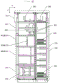
An embodiment of the utility model provides a dc power supply device, this dc power supply device include rectifier cabinet 10, and fig. 1, fig. 2 and fig. 3 are the planar structure sketch map of this rectifier cabinet under different visual angles respectively, and fig. 4 and fig. 5 are the spatial structure sketch map of this rectifier cabinet respectively, and fig. 6 is the electrical connection picture of rectifier cabinet. Fig. 1, 2 and 4 show the external structure of the rectification cabinet, and fig. 3 and 5 show the internal structure of the rectification cabinet.
As shown in fig. 3 and 6, the rectification cabinet 10 includes: the short-circuit protection device comprises a shell 100, an alternating current incoming cable 200, an alternating current breaker 300, a rectifier set 400, a direct current busbar 500, a short-circuit protection appliance 600 and a direct current load end 700. The ac inlet cable 200 is configured to access ac; the ac circuit breaker 300 is located in the casing 100 and includes a first end 301 and a second end 302, the ac incoming cable 200 passes through the casing 100 and is electrically connected with the first end 301 of the ac circuit breaker 300; the rectifier set 400 is located within the housing 100 and includes an ac input 401 and a dc output 402, the ac input 401 of the rectifier set 400 is electrically connected to the second end 302 of the ac circuit breaker 300, the rectifier set 400 is configured to convert ac power to dc power; the direct-current busbar 500 is positioned in the shell 100, and the direct-current busbar 500 is electrically connected with the direct-current output end 402 of the rectifier group 400; the short-circuit protection apparatus 600 is located in the housing 100 and includes a first end 601 and a second end 602, and the first end 601 of the short-circuit protection apparatus 600 is electrically connected to the dc bus bar 500; the dc load terminal 700 is located in the housing 100, and the dc load terminal 700 is electrically connected to the second terminal 602 of the short-circuit protection apparatus 600 and configured to output dc power.
For example, the short-circuit protection apparatus 600 may be a fuse, a dc breaker, or a dc switch.
In the dc power supply device provided in the embodiment of the present invention, the ac incoming cable is used as an incoming end of low-voltage ac power, and the low-voltage ac power is accessed from the outside; the alternating current circuit breaker is an alternating current incoming line switch, and can cut off or switch on a circuit to provide safety guarantee; the rectifier rectifies the low-voltage alternating current into low-voltage direct current; the direct current busbar and the direct current load end are used as direct current output ends and used for supplying power to components; the short-circuit protection electrical appliance is connected to a direct-current busbar and a direct-current load end passage to play a role in preventing overlarge current. The rectifier cabinet can be used as a direct-current power supply cabinet of a large-scale data center. The low-voltage alternating current is alternating current after voltage reduction by the transformer. For example, the external high-voltage or medium-voltage alternating current has a voltage of about 10kV, and is converted into a low-voltage alternating current of about 240V after passing through a transformer, and the low-voltage alternating current outputs a low-voltage direct current of about 240V after passing through a rectifier cabinet. The power of the rectifier cabinet can be 630kW, for example, and the rated operating current of the dc busbar can be 2000A, for example. It should be noted that the voltage, current and power parameters are examples, and the present invention is not limited to specific parameters of the rectifier cabinet.
As shown in fig. 1 to 5, the outer contour of the rectifier cabinet is a rectangular parallelepiped, and the directions of the length, width and height are represented by X, Y, Z as shown in the drawing. Hereinafter, the present invention will be described by way of example, but the shape of the rectifier cabinet is not limited thereto.
As shown in fig. 3, the ac circuit breaker 300 is located in the first isolation room 310, the rectifier set 400 is located in the second isolation room 410, at least a portion of the dc busbar 500 is located in the third isolation room 510, and the short-circuit protection device 600 is located in the fourth isolation room 610. At least a portion of the partitions of the first, second, third and fourth isolation chambers 310, 410, 510 and 610 are made of electrically conductive material and are grounded.
For example, the first, second, third and fourth isolation rooms need not be directly grounded by separate wires, which may be indirectly grounded by the grounding system of the rectification cabinet. For example, the first isolation chamber 310 may have a rectangular parallelepiped shape, all six partitions thereof may be made of a metal material, or some of the partitions thereof may be made of an insulating material, so that the grounding of the first isolation chamber may also be achieved. Similarly, the partition plates of the second isolation chamber, the third isolation chamber and the fourth isolation chamber can be made of metal materials completely, or part of the partition plates can be made of insulating materials.
The rectifier cabinet physically isolates different functional units such as an alternating current breaker, a rectifier set, a direct current busbar and a short-circuit protection electric appliance by arranging a first isolation chamber, a second isolation chamber, a third isolation chamber and a fourth isolation chamber. Therefore, when the functional unit in the isolation chamber has a short-circuit fault, the short-circuit part is easy to generate electric arc due to large current, the isolation chamber has certain structural strength, the damage range of the electric arc can be limited in the isolation chamber, at least part of partition plates of the isolation chamber are made of conductive materials and are grounded, the isolation chamber has grounding continuity, the current can be led into the ground through a grounding system of the rectifier cabinet, the damage range of the faults such as the short circuit can be reduced, and the safety of the rectifier cabinet is improved. Meanwhile, due to the fact that physical isolation is arranged among different functional units, the maintenance convenience of the rectifier cabinet is improved.
For example, the first isolation chamber may also be referred to as an ac breaker chamber, the second isolation chamber may also be referred to as a rectifier chamber, the third isolation chamber may also be referred to as a dc bus bar chamber, and the fourth isolation chamber may also be referred to as a short-circuit protection appliance chamber.
As shown in fig. 3, the rectification cabinet may further include an ac incoming cable compartment 210, a dc load termination compartment 710, and a control component compartment 810. The ac inlet cable 200 is located in the ac inlet cable chamber 210, the dc load terminal 700 is located in the dc load terminal wiring chamber 710, and the control component chamber 810 may be provided with components for monitoring the operation condition of the rectifier cabinet.
For example, at least part of the partitions of the first, second, third and fourth isolation chambers 310, 410, 510 and 610 may be formed by splicing steel plates. The steel plates are spliced, so that the isolation chamber has certain structural strength and the grounding continuity of the isolation chamber can be realized. Of course, other conductive materials can be used for the first isolation chamber 310, the second isolation chamber 410, the third isolation chamber 510 and the fourth isolation chamber 610.
In some examples, the first isolation chamber 310, the second isolation chamber 410, the third isolation chamber 510, and the fourth isolation chamber 610 are removably mounted within the housing 100. Thus, the maintenance convenience of the corresponding part can be improved.
For example, as shown in fig. 4, the rectifying cabinet provided by the present invention is a fully assembled rectifying cabinet, that is, the casing 100 is detachably connected by a plurality of connecting plates, and a plurality of functional units inside the rectifying cabinet are detachably mounted in the casing 100. In addition, the case 100 is provided with openable doors at positions corresponding to the first, second, third and fourth isolation chambers 310, 410, 510 and 610 to facilitate maintenance of the positions.
For example, as shown in fig. 3, the ac incoming cable compartment 210 is located at the lower right end of the rectification cabinet, the first isolation compartment 310 is located at the lower left end of the rectification cabinet, the second isolation compartment 410 is located at the upper side of the first isolation compartment 310, the third isolation compartment 510 is located at the upper side of the second isolation compartment 410, the fourth isolation compartment 610 is located at the upper side of the third isolation compartment 510, and the dc load terminal 700 is located at the upper side of the fourth isolation compartment 610. That is, the third isolation chamber 510 is located on the side of the second isolation chamber 410 away from the first isolation chamber 310, and the fourth isolation chamber 610 is located on the side of the third isolation chamber 510 away from the second isolation chamber 410. According to the layout, the lower end alternating current incoming line and the upper end direct current outgoing line can be realized, the safety is high, the functional modules are clear, and the layout is reasonable. In addition, the rectifier cabinet integrates the functions of alternating current incoming lines and direct current outgoing lines, and can be simply copied and expanded according to load capacity.
For example, adjacent compartments may share a partition, thereby saving costs.
It should be noted that the embodiment of the present invention does not limit that the first isolation room 310, the second isolation room 410, the third isolation room 510 and the fourth isolation room 610 completely isolate the inside and the outside of the device. For example, a wall surface of the first isolation room 310 may be provided with a connection hole for connecting an ac incoming cable to an ac circuit breaker or connecting the ac circuit breaker and a rectifier via a cable, and a heat dissipation hole for circulating air to enhance a heat dissipation effect. Similarly, the second isolation chamber 410, the third isolation chamber 510 and the fourth isolation chamber 610 may also have a connection hole and a heat dissipation hole on the wall surface.
The number of the rectifier groups 400 may be multiple, the dc output terminals 402 of the plurality of rectifier groups 400 are electrically connected to the dc bus bar 500, and each rectifier group 400 may include at least one rectifier. The number of the ac breakers 300 may be plural, and the plurality of ac breakers 300 are electrically connected to the plurality of rectifier groups 400 in one-to-one correspondence.
For example, as shown in fig. 6, the rectifier cabinet includes 3 rectifier groups 400, each rectifier group 400 including 4 rectifiers. The rectifier cabinet comprises 3 alternating current breakers 300, and the 3 alternating current breakers 300 are electrically connected with the 3 rectifier groups 400 in a one-to-one correspondence manner.
For example, as shown in fig. 6, the rectifier cabinet includes 8 short-circuit protectors 600 and 8 dc load terminals 700 (each of the short-circuit protectors 600 and the dc load terminals 700 in the figure includes two short-circuit protectors and two dc load terminals). The rated working current of the short-circuit protection electric appliance can be set according to the actual condition of the load and does not need to be the same. For example, the short-circuit protection devices 630A and 1600A may be disposed on different dc load paths, respectively. The 8 direct current load ends can be connected with the load wholly or partially, and the direct current load end which is not connected with the load can be used as a standby interface. For example, the load includes a power consumption component and a battery. The storage battery can be used as a temporary power supply for the electric components when power is accidentally cut off. Of course, the short-circuit protection device 600 and the dc load terminal 700 may be in other quantities, which is not limited by the embodiment of the present invention.
The utility model provides a rectifier cabinet still is provided with heat radiation structure to reduce the temperature in the cabinet. Fig. 7 is a schematic structural view of a heat dissipation flow channel of a rectification cabinet, showing a flow channel of cooling air in the cabinet.
For example, as shown in fig. 1, 2, and 7, the case 100 includes a first door panel 101 and a second door panel 102 that are oppositely disposed in a first direction (Y direction). The first door panel 101 includes a first air outlet 1011, an air inlet 1012 and a second air outlet 1013 sequentially arranged along a second direction (Z direction), and the second door panel includes a third air outlet 1021, a fourth air outlet 1022 and a fifth air outlet 1023 sequentially arranged along the second direction, which forms an angle with the first direction. A fan 1014 is further disposed in the rectifier set 400, and is configured to suck air from the air inlet 1012 and discharge the air from the first air outlet 1011, the second air outlet 1013, the third air outlet 1021, the fourth air outlet 1022, and the fifth air outlet 1023. In the drawings, the second direction and the first direction are perpendicular to each other only as an example, and the second direction and the first direction may not be perpendicular to each other, which is not limited by the present invention.
In the heat dissipation structure, the arrangement positions of the air inlet, the air outlets and the air flow channel are optimized, heat dissipation of the heating functional units (such as a rectifier, a short-circuit protection electric appliance, an alternating current circuit breaker and an alternating current incoming cable) is facilitated, the heat dissipation performance of the rectifier cabinet is improved, and the stability of the rectifier cabinet in long-term operation is maintained.
In some examples, as shown in fig. 1 and 2, the first air outlet 1011 and the second air outlet 1013 are respectively located at two ends of the first door panel 101 in the second direction, and the third air outlet 1021 and the fifth air outlet 1023 are respectively located at two ends of the second door panel 102 in the second direction. So, be favorable to cooling to being located AC inlet wire cable, AC circuit breaker and short-circuit protection electrical apparatus of upper and lower both sides.
In some examples, as shown in fig. 7, the intake vent 1012 is located at a position corresponding to a fan 1014 of the rectifier bank 400. In this way, cooling of the rectifier group is facilitated.
For example, through simulation calculations, the heat dissipation structure may reduce the maximum temperature within the rectifier cabinet to within 100 degrees celsius.
In some examples, an intelligent digital monitoring system 801 is disposed within the control element room 810. The intelligent digital monitoring system can comprise a gateway, a human-computer interaction interface and other functional components.
In some examples, as shown in fig. 3 and 5, dc busbar 500 includes two terminals connecting rectifier group 400 and short-circuit protection device 600 in the Z-direction, the two terminals being located in third isolation chamber 510 and fourth isolation chamber 610, respectively. The dc busbar 500 further includes a metal conductor 501 extending along the X direction, and the metal conductor 501 may pass through the side plate of the housing 100 along the X direction to be connected with the metal conductor 501 of the adjacent rectifier cabinet, so that the dc busbars 500 of the adjacent rectifier cabinets are connected to each other to share the energy, and thus, when the load distribution of the dc load terminal 700 is uneven, the energy utilization efficiency is improved.
For example, the dc bus bar 500 may be made of a material with good electrical conductivity, such as copper.
The rectifier cabinet can two or many use as a set of, and the female 500 interconnect that arranges of direct current of two or many rectifier cabinets to can the shared energy.
For example, the dc power supply device further includes a rectifier cabinet group 1, which includes two rectifier cabinets 10 provided in any of the above embodiments, fig. 8 is a schematic perspective view of the rectifier cabinet group, and fig. 9 is an electrical connection diagram of the rectifier cabinet group. As shown in fig. 9, two rectifying cabinets 10 are arranged side by side, and their dc busbars 500 are connected to each other. The two rectifier cabinets of the rectifier cabinet group can share the energy, so that the energy utilization efficiency is improved.
An embodiment of the present invention further provides a voltage transformation rectification power supply system, and fig. 10 is a schematic diagram of a three-dimensional structure of the voltage transformation rectification power supply system. As shown in fig. 10, the transformer rectification power supply system includes an ac power supply cabinet 2, a phase-shifting transformer 3 and the dc power supply apparatus provided in the above embodiment, which are arranged in sequence.
The phase-shifting transformer 3 is respectively connected to the ac power supply cabinet 2 and the ac incoming cable 200 of each rectifier cabinet 10 in the dc power supply device, and configured to step down the ac power in the ac power supply cabinet 2 and output the ac power to each rectifier cabinet 10.
For example, the ac power supply cabinet 2 supplies 10kV ac power, the phase-shifting transformer 3 steps down the ac power to output 240V ac power, the ac power is connected to the rectifier cabinet assembly 1 via the ac incoming cable 200, and the rectifier cabinet assembly outputs dc power as a power source for a data center or other electric devices. The voltage value is only an example, and the present invention does not limit the voltage value.
In some examples, the number of the rectifier cabinet groups 1 is multiple, and the rectifier cabinet groups are arranged in sequence along the direction of the rectifier cabinet groups far away from the phase-shifting transformer. For one rectifier cabinet in the rectifier cabinet group, which is positioned at one side far away from the phase-shifting transformer, an alternating current inlet cable of the rectifier cabinet group penetrates through other rectifier cabinets positioned between the phase-shifting transformer and the rectifier cabinet.
For example, as shown in fig. 10, the transformer rectifier power supply system includes 8 rectifier cabinets in 4 rectifier cabinet groups. For example, fig. 3 shows that there are 8 rows of 72 ac incoming cables 200 in the rectifying cabinet, but the 72 ac incoming cables 200 do not need to be all connected to the ac circuit breaker 300. For example, for a rectifier cabinet including 3 ac circuit breakers, each ac circuit breaker needs to be connected to 3 ac incoming cables, and a total of 9 ac incoming cables are needed, and the remaining ac incoming cables pass through the casing of the rectifier cabinet and are connected to the remaining rectifier cabinet, and each time the ac incoming cables pass through one rectifier cabinet, 9 ac incoming cables are reduced, and 9 ac incoming cables remain when the ac incoming cables reach the final rectifier cabinet. Therefore, the rectifier cabinet shown in fig. 3 can be used as the rectifier cabinet closest to the phase-shifting transformer, and can also meet the ac incoming line of the subsequent 7 rectifier cabinets. Of course, the quantity of exchanging inlet wire cable can be according to the quantity of rectifier cabinet and the quantity setting of exchanging circuit breaker in every rectifier cabinet, the utility model discloses do not injecing to this.
The alternating current incoming cable penetrates through the rectifier cabinet close to the phase-shifting transformer to be connected into the rear rectifier cabinet, so that the alternating current incoming cable is more reasonable in wiring and is beneficial to heat dissipation and installation of the alternating current incoming cable.
For example, the two voltage transformation rectification power supply systems can be used together, the two voltage transformation rectification power supply systems are arranged oppositely, 4 rectifier cabinet groups of each voltage transformation rectification power supply system are arranged oppositely one by one, and the direct current busbars 500 of each pair of oppositely arranged rectifier cabinet groups 1 can be connected with each other, so that energy sources are further shared, and the energy utilization rate is improved.
The voltage transformation rectification power supply system can convert external high-voltage alternating current into low-voltage direct current required by electric equipment such as a data center and the like, and has the beneficial technical effects of high safety, convenience in maintenance, high energy efficiency, compact layout and the like.
Finally, it should be noted that the present invention is generally illustrated by one/a pair of components when describing the position of each component and the matching relationship therebetween, however, it should be understood by those skilled in the art that such position, matching relationship, etc. are also applicable to other components/other pairs of components.
The above description is only an exemplary embodiment of the present invention, and is not intended to limit the scope of the present invention, which is defined by the appended claims.
Claims (11)
1. A dc power supply device, characterized by comprising a rectifying cabinet (10), said rectifying cabinet (10) comprising:
a housing (100);
an alternating current inlet cable (200) configured to be switched in alternating current;
an AC circuit breaker (300) located within the housing (100) and comprising a first end (301) and a second end (302), the AC inlet cable (200) passing through the housing (100) and being electrically connected to the first end (301) of the AC circuit breaker (300);
a rectifier group (400) located within the housing (100) and comprising an alternating current input (401) and a direct current output (402), the alternating current input (401) of the rectifier group (400) being electrically connected with the second end (302) of the alternating current circuit breaker (300), the rectifier group (400) being configured to convert alternating current to direct current;
the direct current busbar (500) is positioned in the shell (100), and the direct current busbar (500) is electrically connected with a direct current output end (402) of the rectifier group (400);
the short-circuit protection electric appliance (600) is positioned in the shell (100) and comprises a first end (601) and a second end (602), and the first end (601) of the short-circuit protection electric appliance (600) is electrically connected with the direct-current busbar (500); and
a DC load terminal (700) located within the housing (100), the DC load terminal (700) being electrically connected to the second terminal (602) of the short-circuit protection appliance (600) and configured to output DC power,
wherein, alternating current circuit breaker (300) is located first isolation room (310), rectifier group (400) are located second isolation room (410), at least a part that the female row of direct current (500) is located third isolation room (510), short-circuit protection electrical apparatus (600) are located fourth isolation room (610), first isolation room (310), second isolation room (410), third isolation room (510) and at least part baffle of fourth isolation room (610) are made by electrically conductive material and ground connection.
2. The DC power supply of claim 1, wherein the third isolation chamber (510) is located on a side of the second isolation chamber (410) away from the first isolation chamber (310), and the fourth isolation chamber (610) is located on a side of the third isolation chamber (510) away from the second isolation chamber (410).
3. The DC power supply of claim 1, wherein the first isolation chamber (310), the second isolation chamber (410), the third isolation chamber (510), and the fourth isolation chamber (610) are removably mounted within the housing (100).
4. The dc power supply device according to claim 1, wherein the number of the rectifier groups (400) is plural, the dc output terminals (402) of the plurality of rectifier groups (400) are electrically connected to the dc bus bar (500), and each rectifier group (400) comprises at least one rectifier.
5. The DC power supply device according to claim 4, wherein the number of the AC circuit breakers (300) is plural, and the plural AC circuit breakers (300) are electrically connected to the plural rectifier groups (400) in a one-to-one correspondence.
6. The DC power supply according to claim 1, wherein the housing (100) comprises a first door panel (101) and a second door panel (102) arranged opposite to each other in a first direction, the first door panel (101) comprises a first air outlet (1011), an air inlet (1012) and a second air outlet (1013) which are sequentially arranged along a second direction, the second door panel (102) comprises a third air outlet (1021), a fourth air outlet (1022) and a fifth air outlet (1023) which are sequentially arranged along a second direction, the second direction forms an angle with the first direction, and a fan (1014) configured to suck air from the air inlet (1012) and discharge the air from the first air outlet (1011), the second air outlet (1013), the third air outlet (1021), the fourth air outlet (1022) and the fifth air outlet (1023) is further disposed in the rectifier set (400).
7. The DC power supply device according to claim 6, wherein the first outlet (1011) and the second outlet (1013) are respectively located at two ends of the first door panel (101) along the second direction, and the third outlet (1021) and the fifth outlet (1023) are respectively located at two ends of the second door panel (102) along the second direction.
8. The DC power supply according to claim 6, wherein the air inlet (1012) is located at a position corresponding to a fan (1014) of the rectifier bank (400).
9. The dc power supply device according to any one of claims 1 to 8, comprising a rectifier cabinet group (1), wherein the rectifier cabinet group (1) comprises two rectifier cabinets (10), and the dc busbars (500) of the two rectifier cabinets (10) are connected to each other.
10. A transformation rectification power supply system, characterized by comprising an ac power supply cabinet (2), a phase-shifting transformer (3) and the dc power supply device according to claim 9, which are arranged in sequence, wherein the phase-shifting transformer (3) is respectively connected with the ac incoming cable (200) of each of the ac power supply cabinet (2) and the dc power supply device (10), and is configured to step down the ac power in the ac power supply cabinet (2) and output the ac power to each of the rectification cabinets (10).
11. The system according to claim 10, comprising a plurality of rectifier cabinet groups (1) arranged in sequence in the direction of the dc power supply device away from the phase-shifting transformer (3), wherein for one rectifier cabinet (10) of the rectifier cabinet groups (1) located at the side away from the phase-shifting transformer (3), its ac incoming cable (200) passes through the other rectifier cabinets (10) located between the phase-shifting transformer (3) and the rectifier cabinet (10).
Priority Applications (1)
| Application Number | Priority Date | Filing Date | Title |
|---|---|---|---|
| CN202022464606.4U CN213817242U (en) | 2020-10-30 | 2020-10-30 | Direct current power supply device and transformation rectification power supply system |
Applications Claiming Priority (1)
| Application Number | Priority Date | Filing Date | Title |
|---|---|---|---|
| CN202022464606.4U CN213817242U (en) | 2020-10-30 | 2020-10-30 | Direct current power supply device and transformation rectification power supply system |
Publications (1)
| Publication Number | Publication Date |
|---|---|
| CN213817242U true CN213817242U (en) | 2021-07-27 |
Family
ID=76963182
Family Applications (1)
| Application Number | Title | Priority Date | Filing Date |
|---|---|---|---|
| CN202022464606.4U Active CN213817242U (en) | 2020-10-30 | 2020-10-30 | Direct current power supply device and transformation rectification power supply system |
Country Status (1)
| Country | Link |
|---|---|
| CN (1) | CN213817242U (en) |
Cited By (2)
| Publication number | Priority date | Publication date | Assignee | Title |
|---|---|---|---|---|
| CN113910938A (en) * | 2021-09-09 | 2022-01-11 | 郑州森源新能源科技有限公司 | DC charging equipment |
| CN114765425A (en) * | 2022-05-17 | 2022-07-19 | 广东首航智慧新能源科技有限公司 | Parallel assembly of rectifier modules, rectifier cabinet and direct-current power supply system thereof |
-
2020
- 2020-10-30 CN CN202022464606.4U patent/CN213817242U/en active Active
Cited By (4)
| Publication number | Priority date | Publication date | Assignee | Title |
|---|---|---|---|---|
| CN113910938A (en) * | 2021-09-09 | 2022-01-11 | 郑州森源新能源科技有限公司 | DC charging equipment |
| CN114765425A (en) * | 2022-05-17 | 2022-07-19 | 广东首航智慧新能源科技有限公司 | Parallel assembly of rectifier modules, rectifier cabinet and direct-current power supply system thereof |
| CN114765425B (en) * | 2022-05-17 | 2023-01-17 | 上海百竹成航新能源有限责任公司 | Parallel assembly of rectifier modules, rectifier cabinet and direct-current power supply system thereof |
| US11742772B1 (en) | 2022-05-17 | 2023-08-29 | Shanghai Baizhu Chenghang New Energy Co., Ltd. | Parallel assembly of rectifier modules, rectifier cabinet and dc power supply system thereof |
Similar Documents
| Publication | Publication Date | Title |
|---|---|---|
| US9312665B2 (en) | Electrical distribution systems incuding parallel energy source and methods | |
| CN213817242U (en) | Direct current power supply device and transformation rectification power supply system | |
| US20080055822A1 (en) | Scalable plant with top or bottom entry flexibility | |
| US20170300100A1 (en) | Power supply device and server system provided with same | |
| WO2015176577A1 (en) | Miniature photovoltaic combiner box | |
| CN114765425B (en) | Parallel assembly of rectifier modules, rectifier cabinet and direct-current power supply system thereof | |
| CN211239235U (en) | Composite bus | |
| CN212991912U (en) | Bus distribution device | |
| CN219287001U (en) | Cabinet and transformer substation for photovoltaic power generation | |
| CN113852205A (en) | High-performance plug-and-play micro-grid energy storage system | |
| CN111082378A (en) | Composite bus | |
| CN110492721B (en) | Multiport power electronic transformer | |
| WO2022110098A1 (en) | Miniaturized module-integrated 400 v low-voltage switch cabinet | |
| WO2022170578A1 (en) | Inverter device and inverter system | |
| CN213093888U (en) | High-performance plug-and-play micro-grid energy storage system | |
| CN109068525A (en) | A kind of standard PC case structure of DC-DC power module | |
| CN208209279U (en) | High voltage direct current power distribution cabinet | |
| CN209823269U (en) | Separated high-voltage switch cabinet | |
| CN212381098U (en) | Power unit assembly, power unit device and high-voltage frequency converter | |
| CN210092646U (en) | Outdoor four-port electric energy router structure | |
| CN210693523U (en) | Modularized charging equipment | |
| CN214589727U (en) | Branch distributed secondary switching cabinet | |
| CN212751349U (en) | Bus switching distribution device | |
| CN221428604U (en) | Cascade energy storage device | |
| CN221806211U (en) | Dual-power cabinet |
Legal Events
| Date | Code | Title | Description |
|---|---|---|---|
| GR01 | Patent grant | ||
| GR01 | Patent grant |