CN213816290U - Battery pack - Google Patents
Battery pack Download PDFInfo
- Publication number
- CN213816290U CN213816290U CN202023112484.9U CN202023112484U CN213816290U CN 213816290 U CN213816290 U CN 213816290U CN 202023112484 U CN202023112484 U CN 202023112484U CN 213816290 U CN213816290 U CN 213816290U
- Authority
- CN
- China
- Prior art keywords
- battery
- protective cover
- cover
- insulating protective
- battery cell
- Prior art date
- Legal status (The legal status is an assumption and is not a legal conclusion. Google has not performed a legal analysis and makes no representation as to the accuracy of the status listed.)
- Active
Links
Images

Classifications
-
- Y—GENERAL TAGGING OF NEW TECHNOLOGICAL DEVELOPMENTS; GENERAL TAGGING OF CROSS-SECTIONAL TECHNOLOGIES SPANNING OVER SEVERAL SECTIONS OF THE IPC; TECHNICAL SUBJECTS COVERED BY FORMER USPC CROSS-REFERENCE ART COLLECTIONS [XRACs] AND DIGESTS
- Y02—TECHNOLOGIES OR APPLICATIONS FOR MITIGATION OR ADAPTATION AGAINST CLIMATE CHANGE
- Y02E—REDUCTION OF GREENHOUSE GAS [GHG] EMISSIONS, RELATED TO ENERGY GENERATION, TRANSMISSION OR DISTRIBUTION
- Y02E60/00—Enabling technologies; Technologies with a potential or indirect contribution to GHG emissions mitigation
- Y02E60/10—Energy storage using batteries
Abstract
The utility model relates to a battery pack, include: the box body is internally provided with a battery cell module, the battery cell module comprises a plurality of battery cells which are sequentially arranged, and a conducting strip is assembled on an electrode at the top of each battery cell in a conducting manner so as to realize the conducting connection of the corresponding battery cells; the metal box cover is arranged on the box body; the insulating protective cover is positioned between the metal box cover and the conducting strip, so that the metal box cover, the conducting strip and the electrode of the battery cell are insulated and isolated; the insulating protective cover is fixed to the top of the battery cell module in an adhesive mode or fixed to the inner side of the metal box cover in an adhesive mode. The utility model provides an among the battery package, insulating protection casing is fixed through sticky mode, need not dispose the buckle structure at insulating protection casing and corresponding complex position, can simplify insulating protection casing structure to can reduce manufacturing assembly cost.
Description
Technical Field
The utility model relates to a battery pack.
Background
With the development of pure electric vehicles, the requirements on power batteries are higher and higher. The cell monomer energy density in the new energy industry is basically on a similar horizontal line. Before the battery technology does not realize breakthrough, in order to improve the system energy density of the battery pack, the grouping efficiency of the battery pack needs to be continuously improved (the grouping efficiency is the ratio of the total weight of the battery cells of the battery pack to the total weight of the battery pack). In order to meet the requirement, the conventional battery pack generally adopts a CTP grouping form, redundant auxiliary parts are removed, the weight of structural members outside the battery core is reduced, and the energy density of the battery pack is improved accordingly.
A combined battery pack is disclosed in the patent of the Chinese utility model with the publication number of CN209896150U, which comprises a box body and a box cover, a plurality of electric cores arranged in sequence are arranged in the box body, and the box cover is buckled. For guaranteeing intensity, the box and the case lid can select the metal material usually, and the electricity core top is provided with electrically conductive aluminium bar, realizes that electric core series connection arranges. Generally speaking, the metal case lid is nearer apart from the aluminium bar at electricity core top, has insulating inefficacy's risk, consequently, can set up insulating protection casing between aluminium bar and metal case lid usually to realize insulating protection.
The existing insulating protective cover is manufactured by adopting insulating plastics, at present, the insulating protective cover is manufactured by adopting a plastic uptake scheme, and a buckle structure is arranged on the insulating protective cover so as to be conveniently connected with a cell pressing strip on a cell in a buckle way. This kind of mode assembly of buckle connection needs processing preparation buckle structure on insulating protective cover to electric core layering design processing cooperation structure on electric core, makes preparation assembly cost higher, moreover, adopts the mode of buckle connection, requires that electric core layering possesses sufficient intensity, guarantees can not damaged the dropout easily.
SUMMERY OF THE UTILITY MODEL
An object of the utility model is to provide a battery pack to need set up buckle structure and lead to making the higher technical problem of assembly cost on insulating protection cover when adopting buckle connected mode assembly insulating protection cover among the solution prior art.
In order to achieve the above object, the utility model provides a battery pack's technical scheme is: a battery pack, comprising:
the box body is internally provided with a battery cell module, the battery cell module comprises a plurality of battery cells which are sequentially arranged, and a conducting strip is assembled on an electrode at the top of each battery cell in a conducting manner so as to realize the conducting connection of the corresponding battery cells;
the metal box cover is arranged on the box body;
the insulating protective cover is positioned between the metal box cover and the conducting strip, so that the metal box cover, the conducting strip and the electrode of the battery cell are insulated and isolated;
the insulating protective cover is fixed to the top of the battery cell module in an adhesive mode or fixed to the inner side of the metal box cover in an adhesive mode.
The beneficial effects are that: the utility model provides an among the battery package, insulating protection casing is fixed through sticky mode, need not dispose the buckle structure at insulating protection casing and corresponding complex position, can simplify insulating protection casing structure to can reduce manufacturing assembly cost.
As further improvement the insulating protective cover is adhesive-bonded in during the electricity core module top, the electricity core module includes the module end plate, and the module end plate is located the corresponding tip of arranging the electric core, and the electricity core module still includes electric core layering, and electric core layering is located electricity core module top, and the electricity core layering is fixed on the module end plate to corresponding electric core of roof pressure down, the insulating protective cover with the sticky fixed connection of electric core layering.
The beneficial effects are that: insulating protective cover and electric core layering sticky fixed, not only effectively realized the fixed to insulating protective cover, still reducible influence to the conducting strip.
As a further improvement, the cell pressing strip is a plastic pressing strip.
The beneficial effects are that: because of adopting the adhesive fixation, the requirement on the electric core pressing strip is reduced, the plastic pressing strip can be adopted, the requirements on parts are reduced, and the cost can be further reduced.
As a further improvement, the insulating protective cover is fixedly bonded with the cell pressing strip through a double-sided adhesive tape.
The beneficial effects are that: realize the fixed of insulating protection casing through the double faced adhesive tape, conveniently realize.
As a further improvement, the upper side of the insulation protection cover is provided with a crease line corresponding to the position of the double-sided adhesive tape so as to guide an operator to apply pressure correspondingly.
The beneficial effects are that: and the indentation line is preset, so that the pressing, bonding and fixing are facilitated.
As a further improvement, at least two module positioning holes arranged at intervals are formed in the battery cell module, and a plurality of protection cover positioning holes in one-to-one correspondence with the module positioning holes are formed in the insulating protection cover and used for guiding and assembling the insulating protection cover.
The beneficial effects are that: by matching the module positioning hole and the protective cover positioning hole, during assembly, people can observe or match the tool positioning pin to realize positioning assembly.
As a further improvement, when the insulating protective cover is adhesively fixed on the inside of the metal box cover, the circumferential side of the insulating protective cover is adhesively fixed with the corresponding circumferential side of the metal box cover, so that the insulating protective cover is adhesively fixed on the inside of the metal box cover.
The beneficial effects are that: the circumferential side face of the insulating protective cover and the circumferential side edge of the metal box cover are fixed in an adhesive mode, and bonding acting force is conveniently guaranteed.
As a further improvement, the circumferential side face of the insulating protective cover is fixed with the corresponding circumferential side edge of the metal box cover by gluing through a double-sided adhesive tape.
The beneficial effects are that: realize sticky fixed, convenient realization through the double faced adhesive tape.
As a further improvement, the insulation protective cover is a plastic bent piece.
The beneficial effects are that: the insulating protective cover is a plastic bending piece, so that the insulating protective cover is convenient to bend, machine and form on a plastic material, and the machining process is simplified.
As a further improvement, the insulating protective cover is a rectangular cover body, three side faces of the rectangular cover body in the circumferential direction are respectively provided with bending flanges, and the bending flanges are mutually independent.
The beneficial effects are that: the adjacent bent flanges are mutually independent, and the bending processing is convenient.
Drawings
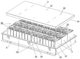
Fig. 1 is a schematic structural diagram of an embodiment 1 of a battery pack provided by the present invention;
fig. 2 is a schematic structural diagram of embodiment 2 of the battery pack provided by the present invention.
Description of reference numerals:
1. a box body; 2. a battery cell module; 20. a conductive sheet; 21. double-sided adhesive tape; 22. pressing strips of the battery core; 23. an electric core; 24. a module end plate; 25. a module spacer; 26. a module positioning hole; 3. an insulating protective cover; 31. a protective cover positioning hole; 32. pressing a crease line; 33. bending and flanging; 4. a metal box cover.
Detailed Description
In order to make the objects, technical solutions and advantages of the present invention more clearly understood, the present invention is further described in detail below with reference to the accompanying drawings and embodiments. It should be understood that the specific embodiments described herein are for purposes of illustration only and are not intended to limit the invention, i.e., the described embodiments are only some, but not all embodiments of the invention. The components of embodiments of the present invention, as generally described and illustrated in the figures herein, may be arranged and designed in a wide variety of different configurations.
Thus, the following detailed description of the embodiments of the present invention, presented in the accompanying drawings, is not intended to limit the scope of the invention, as claimed, but is merely representative of selected embodiments of the invention. Based on the embodiment of the present invention, all other embodiments obtained by the person skilled in the art without creative work belong to the protection scope of the present invention.
It is noted that relational terms such as "first" and "second," and the like, may be used solely to distinguish one entity or action from another entity or action without necessarily requiring or implying any actual such relationship or order between such entities or actions. Also, the terms "comprises," "comprising," or any other variation thereof, are intended to cover a non-exclusive inclusion, such that a process, method, article, or apparatus that comprises a list of elements does not include only those elements but may include other elements not expressly listed or inherent to such process, method, article, or apparatus. Without further limitation, elements recited by the phrase "comprising an … …" do not exclude the inclusion of such elements in processes or methods.
In the description of the present invention, unless otherwise expressly specified or limited, the terms "mounted," "connected," and "connected" when they are used are to be construed broadly, e.g., as meaning either a fixed connection, a removable connection, or an integral connection; can be mechanically or electrically connected; either directly or indirectly through intervening media, or may be interconnected between two elements. The specific meaning of the above terms in the present invention can be understood by those skilled in the art from the specific situation.
In the description of the present invention, it should be noted that, unless explicitly stated or limited otherwise, the term "provided" may be used in a broad sense, for example, the object of "provided" may be a part of the body, or may be arranged separately from the body and connected to the body, and the connection may be a detachable connection or a non-detachable connection. The specific meaning of the above terms in the present invention can be understood by those skilled in the art from the specific situation.
The present invention will be described in further detail with reference to examples.
The utility model provides a specific embodiment 1 of battery package:
as shown in fig. 1, the battery in this embodiment includes a box 1 and a box cover, in order to ensure the supporting strength, the box 1 and the box cover are made of metal, the battery cores 23 are sequentially arranged in the box 1, and the battery core modules 2 are arranged in a row, as shown in fig. 1, three battery core modules 2 are arranged in the box 1, each battery core module 2 includes a plurality of battery cores 23 sequentially arranged in the left-right direction, and the module end plates 24 are respectively arranged at the left and right ends, a module partition plate 25 is arranged in the middle, and all the battery cores 23 in the same module are flattened and tidily by using the battery core pressing strip 22 fixedly connected with the module end plates 24.
In addition, the top of the battery cell 23 is provided with positive and negative electrodes, and in order to realize normal conductive connection to form a power unit, a conductive aluminum bar is provided for one battery cell 23, and the conductive aluminum bar is used as the conductive sheet 20 to conductively connect corresponding positive and negative electrodes of different battery cells 23. Of course, the conductive connection between the different cell modules 2 is also through conductive aluminum bars, so that all the modules are assembled together to form the power unit.
The conductive aluminum bars can be fixedly connected by welding, bolt connection or the like, so that the conductive communication between the positive electrodes and the negative electrodes of different battery cells 23 can be realized, and the conductive aluminum bars can be fixedly assembled with corresponding electrodes and can be assembled by adopting a conventional connection mode in the prior art.
Generally speaking, can adopt corresponding fixed mode to fix all electric core modules 2 together according to actual need, if utilize the ribbon to fix three electric core modules 2 together, convenient assembly. Also can utilize the ribbon to fix each independent electric core module 2 after, put into box 1 in proper order, can adjust according to actual assembly needs.
Place electric core module 2, be less than electric core module 2 electrically conductive connection with the external lead terminal correspondence on box 1, guarantee normal external lead wire after, install the metal case lid on box 1, the fixed assembly of the mode of the sealed assembly of specific accessible flange.
Because the upper portion of electric core module 2 upwards extrudes box 1 and arranges to upwards go deep into in the case lid, can make conducting strip 20 be nearer apart from the metal case lid, for realizing effective insulation, set up insulating protection casing 3 between metal case lid (not shown in figure 1) and conducting strip 20, realize the insulating isolation between the electrode of metal case lid and conducting strip 20, electric core 23.
In this embodiment, the insulating protective cover 3 is fixed on the cell pressing strip 22 by gluing so as to be fixed on the top of the cell module 2. Particularly, the insulating protective cover 3 is a plastic bending piece and can be machined and formed on an existing bending machine, and viewed from the appearance, the insulating protective cover 3 is a rectangular cover body which comprises a middle main cover body and bending flanges 33 arranged on three circumferential side faces respectively, the bending flanges 33 are mutually independent, and can be bent and formed independently when being bent and processed, and of course, an assembly gap can be formed between the adjacent bending flanges, and effective insulating protection cannot be influenced.
The module partition 25 is provided with module positioning holes 26, the two module positioning holes 26 are arranged at intervals to form a positioning structure, the main shield body is provided with two shield positioning holes 31, the two shield positioning holes 31 are arranged in one-to-one correspondence with the two module positioning holes 26, and the shield positioning holes correspond to the module positioning holes to guide and assemble the insulating shield 3. During the assembly, usable people's eye is observed, aligns protection casing locating hole and module locating hole, still can utilize the frock locating pin, and the cartridge is in the protection casing locating hole to with module locating hole plug-in fit, with the positioning assembly of guide insulating protection casing 3.
During assembly, the module positioning hole 26 and the protection cover positioning hole 31 are firstly used for guiding assembly, and then the insulating protection cover 3 is fixedly bonded with the cell pressing strip 22 through the double-sided adhesive tape 21, during specific assembly, the double-sided adhesive tape 21 can be firstly pre-stained on the plastic pressing strip or pre-stained in the large inner plane of the insulating protection cover 3, and then the insulating protection cover 3 is tightly pressed.
Of course, on the insulating protection cover 3, the indentation line 32 may be disposed at a position corresponding to the double-sided tape 21 on the upper side surface of the insulating protection cover 3 to guide the operator to apply pressure correspondingly, so as to avoid reduction of production efficiency due to the fact that the operator does not know the pressing position and the range of pressing, and to avoid damage to the sampling line due to wrong pressing.
After the insulating protective cover 3 is installed, the metal box cover is correspondingly installed on the box body 1.
Foretell insulating protective cover is the plastics piece of bending, and the dead weight is lighter, moreover, still adopts sticky fixed mode, consequently, the fixed requirement of support that insulating protective cover can be satisfied to electric core layering adoption working of plastics, and of course, electric core layering still will satisfy the effect that the roof pressure leveled electric core, still need possess certain intensity.
In this embodiment, insulating protection casing is the piece of bending, and the shaping of can directly bending has avoided the die sinking, can effectively reduce development cycle and development cost. And adopt the mode of sticky fixed, the structure of insulating protection casing and electric core layering is all very simple, does not do special requirement to intensity between them moreover, but reduce cost equally. During assembly, after the insulating protective cover is fixed by glue, the metal box cover is directly installed, so that the development period is effectively shortened, the development cost is reduced, and the production efficiency is improved.
The utility model provides a specific embodiment 2 of battery package:
the difference from example 1 is mainly that: in embodiment 1, the insulating protection casing adhesive fixation is at electric core module top. In this embodiment, the insulating shield is previously adhesively fixed to the inside of the metal case cover.
As shown in fig. 2, the metal box cover 4 itself forms a recess having four circumferential sides, and during assembly, double-sided tapes can be adhered to the outer sides of the corresponding three bent flanges 33 of the insulating shield 3, and then when the insulating shield 3 is placed in the metal box cover 4, the circumferential sides of the insulating shield 3 and the corresponding circumferential sides of the metal box cover are adhesively fixed, so that the insulating shield is adhesively fixed to the inner side of the metal box cover.
In the installation mode, the insulating protective cover can be bonded and fixed on the inner side of the metal box cover in advance, and the metal box cover can be directly installed during installation without independently installing the insulating protective cover.
The utility model provides a specific embodiment 3 of battery package:
the difference from example 1 is mainly that: in embodiment 1, the insulating protective cover is bonded and fixed on the cell pressing strip of the cell module by using a double-sided adhesive tape. In this embodiment, can be according to actual need, save electric core layering, at this moment, can with insulating protection casing adhesive bond fixation on the module end plate, for convenient fixed, can set up the arch on the module end plate, can paste the double faced adhesive tape in the arch, convenient bonding is fixed. At the moment, for convenient preassembly and fixation, module positioning holes can be formed in the module partition plate so as to be convenient for corresponding inserting and positioning with the protection cover positioning holes in the insulating protection cover, the number of the module positioning holes can be arranged according to actual needs, more than three module positioning holes can be arranged, and correspondingly, the number of the protection cover positioning holes also needs to be correspondingly increased.
The utility model provides a specific embodiment 4 of battery package:
the difference from example 1 is mainly that: in embodiment 1, the insulating protective cover is bonded and fixed on the cell pressing strip of the cell module by using a double-sided adhesive tape. In this embodiment china, also can set up a plurality of elongated holes on insulating protective cover for the rubber coating, place insulating protective cover back on electric core layering, can be in elongated hole rubber coating, in order to realize both adhesive fastening.
The utility model provides a specific embodiment 5 of battery package:
the difference from example 2 is mainly that: in embodiment 2, double-sided tapes are arranged on three sides of the insulation protective cover to be fixed with the metal box cover. In this embodiment, the cover body of the insulating protective cover and the metal cover may be bonded and fixed, and a double-sided tape or a glue may be used therebetween.
Finally, it should be noted that the above mentioned embodiments are only preferred embodiments of the present invention, and not intended to limit the present invention, and although the present invention has been described in detail with reference to the foregoing embodiments, it will be apparent to those skilled in the art that modifications may be made without inventive effort to the technical solutions described in the foregoing embodiments, or equivalents may be substituted for some of the technical features. Any modification, equivalent replacement, or improvement made within the spirit and principle of the present invention should be included in the protection scope of the present invention.
Claims (10)
1. A battery pack, comprising:
the battery cell module (2) is arranged in the box body (1), the battery cell module (2) comprises a plurality of battery cells (23) which are sequentially arranged, and a conducting strip (20) is conductively assembled on an electrode at the top of each battery cell (23) so as to realize conductive connection of the corresponding battery cells (23);
the metal box cover (4) is arranged on the box body (1);
the insulating protective cover (3) is positioned between the metal box cover (4) and the conducting strip (20) to realize the insulating isolation between the metal box cover (4) and the conducting strip (20) and between the electrodes of the battery core (23);
the battery is characterized in that the insulating protective cover (3) is fixed to the top of the battery core module (2) in an adhesive mode or fixed to the inner side of the metal box cover (4) in an adhesive mode.
2. The battery pack according to claim 1, wherein the insulating protective cover (3) is fixed to the top of the battery cell module (2) by gluing, the battery cell module (2) comprises a module end plate, the module end plate is located at the end of a correspondingly arranged battery cell (23), the battery cell module (2) further comprises a battery cell pressing strip (22), the battery cell pressing strip (22) is located at the top of the battery cell module (2), the battery cell pressing strip (22) is fixed to the module end plate and presses the corresponding battery cell (23) downwards, and the insulating protective cover (3) is fixedly connected to the battery cell pressing strip (22) by gluing.
3. The battery pack of claim 2, wherein the cell bead (22) is a plastic bead.
4. The battery pack according to claim 2, wherein the insulating protective cover (3) is adhesively fixed to the cell bead (22) by a double-sided adhesive tape (21).
5. The battery pack according to claim 4, wherein the upper side of the insulating protection cover (3) is provided with a crease line (32) corresponding to the position of the double-sided adhesive tape (21) to guide the operator to apply pressure correspondingly.
6. The battery pack according to claim 2, wherein the cell module (2) is provided with at least two module positioning holes (26) arranged at intervals, and the insulating protective cover (3) is provided with a plurality of protective cover positioning holes (31) corresponding to the module positioning holes (26) one by one for guiding and assembling the insulating protective cover (3).
7. A battery pack according to claim 1, wherein, when the insulating protective cover (3) is adhesively secured inside the metal case cover (4), the circumferential side of the insulating protective cover (3) is adhesively secured with the corresponding circumferential side of the metal case cover (4) so that the insulating protective cover (3) is adhesively secured inside the metal case cover (4).
8. Battery pack according to claim 7, characterized in that the circumferential sides of the insulating protective cover (3) are adhesively fixed to the corresponding circumferential sides of the metal lid (4) by means of double-sided adhesive tape (21).
9. Battery pack according to any of claims 1 to 8, characterized in that the insulating shield (3) is a plastic bent piece.
10. The battery pack according to claim 9, wherein the insulating protective cover (3) is a rectangular cover body, and three sides of the rectangular cover body in the circumferential direction are respectively provided with a bent flange (33), and the bent flanges are independent of each other.
Priority Applications (1)
| Application Number | Priority Date | Filing Date | Title |
|---|---|---|---|
| CN202023112484.9U CN213816290U (en) | 2020-12-22 | 2020-12-22 | Battery pack |
Applications Claiming Priority (1)
| Application Number | Priority Date | Filing Date | Title |
|---|---|---|---|
| CN202023112484.9U CN213816290U (en) | 2020-12-22 | 2020-12-22 | Battery pack |
Publications (1)
| Publication Number | Publication Date |
|---|---|
| CN213816290U true CN213816290U (en) | 2021-07-27 |
Family
ID=76947264
Family Applications (1)
| Application Number | Title | Priority Date | Filing Date |
|---|---|---|---|
| CN202023112484.9U Active CN213816290U (en) | 2020-12-22 | 2020-12-22 | Battery pack |
Country Status (1)
| Country | Link |
|---|---|
| CN (1) | CN213816290U (en) |
Cited By (1)
| Publication number | Priority date | Publication date | Assignee | Title |
|---|---|---|---|---|
| DE102021209745A1 (en) | 2021-09-03 | 2023-03-09 | Mahle International Gmbh | accumulator arrangement |
-
2020
- 2020-12-22 CN CN202023112484.9U patent/CN213816290U/en active Active
Cited By (1)
| Publication number | Priority date | Publication date | Assignee | Title |
|---|---|---|---|---|
| DE102021209745A1 (en) | 2021-09-03 | 2023-03-09 | Mahle International Gmbh | accumulator arrangement |
Similar Documents
| Publication | Publication Date | Title |
|---|---|---|
| CN206774613U (en) | A kind of soft-package battery module and its module framework | |
| CN208256788U (en) | A kind of soft bag lithium ionic cell module | |
| CN213816290U (en) | Battery pack | |
| CN208111502U (en) | Hard shell lithium battery mould group | |
| CN114447407A (en) | Cylindrical battery and manufacturing method thereof | |
| CN206076351U (en) | A kind of battery case and its lithium battery module | |
| CN109193019B (en) | Soft package module structure of battery | |
| CN214313459U (en) | A sampling subassembly for battery module | |
| CN212874703U (en) | Soft packet of lithium ion battery group of integrated into one piece's interior cluster | |
| CN211860048U (en) | Five-string photovoltaic assembly | |
| CN210325937U (en) | Novel battery module | |
| CN220209152U (en) | Energy sheet battery | |
| CN212991106U (en) | Plug-in type photovoltaic small assembly | |
| CN219917424U (en) | Side plate assembly and battery module | |
| CN219658807U (en) | Power battery module structure | |
| CN214589134U (en) | Energy storage battery module | |
| CN110323388B (en) | Soft package battery cell pack, riveting method of soft package battery cell pack and riveting die of soft package battery cell pack | |
| CN212823625U (en) | Battery module installation welding frock | |
| CN212725506U (en) | Lithium battery pack structure for UPS energy storage module | |
| CN216698563U (en) | Novel electricity core waterproof construction | |
| CN218919193U (en) | Battery module and frame thereof | |
| CN217468616U (en) | Integrated non-module battery pack | |
| CN219937206U (en) | Battery cell | |
| CN219350595U (en) | Battery module | |
| CN114649436B (en) | Novel photovoltaic module and preparation method thereof |
Legal Events
| Date | Code | Title | Description |
|---|---|---|---|
| GR01 | Patent grant | ||
| GR01 | Patent grant |