CN213791868U - Ore crusher with automatic feeding mechanism - Google Patents
Ore crusher with automatic feeding mechanism Download PDFInfo
- Publication number
- CN213791868U CN213791868U CN202022417688.7U CN202022417688U CN213791868U CN 213791868 U CN213791868 U CN 213791868U CN 202022417688 U CN202022417688 U CN 202022417688U CN 213791868 U CN213791868 U CN 213791868U
- Authority
- CN
- China
- Prior art keywords
- conveying
- crushing
- groups
- rollers
- roller
- Prior art date
- Legal status (The legal status is an assumption and is not a legal conclusion. Google has not performed a legal analysis and makes no representation as to the accuracy of the status listed.)
- Expired - Fee Related
Links
- 230000007246 mechanism Effects 0.000 title claims abstract description 30
- 238000003466 welding Methods 0.000 claims abstract description 4
- 230000005540 biological transmission Effects 0.000 claims description 23
- 230000003014 reinforcing effect Effects 0.000 claims description 7
- 229910052500 inorganic mineral Inorganic materials 0.000 claims 6
- 239000011707 mineral Substances 0.000 claims 6
- 239000000463 material Substances 0.000 abstract description 4
- 230000006978 adaptation Effects 0.000 abstract 1
- 238000012216 screening Methods 0.000 description 6
- 238000000034 method Methods 0.000 description 4
- 230000000903 blocking effect Effects 0.000 description 3
- 238000009434 installation Methods 0.000 description 3
- 239000002994 raw material Substances 0.000 description 3
- 238000004519 manufacturing process Methods 0.000 description 2
- 230000002787 reinforcement Effects 0.000 description 2
- 230000009286 beneficial effect Effects 0.000 description 1
- 238000010276 construction Methods 0.000 description 1
- 230000002349 favourable effect Effects 0.000 description 1
- 230000005484 gravity Effects 0.000 description 1
- 238000005065 mining Methods 0.000 description 1
- 230000001737 promoting effect Effects 0.000 description 1
- 238000007670 refining Methods 0.000 description 1
- 239000002699 waste material Substances 0.000 description 1
Images


Landscapes
- Crushing And Grinding (AREA)
- Disintegrating Or Milling (AREA)
Abstract
The utility model relates to an ore crushing equipment technical field specifically is an ore crusher with automatic feeding mechanism, including the breaker main part, the breaker main part is including broken storehouse, and the fixed welding in top in broken storehouse has the feeder hopper, the inside intermediate position symmetry form in broken storehouse is rotated and is connected with the crushing roller, and every group the equal fixed welding in back one end of crushing roller has the gear, and is two sets of the tooth looks adaptation of assembly on the gear outer wall. The utility model discloses a set up the carriage slope form and erect in the left side in broken storehouse, through first conveyer belt rotary motion, carry out the conveying material loading to the ore, need not to adopt other external loading attachment, the effectual time loss when avoiding installing loading attachment, the breaker fast work of being convenient for uses, and the intermediate position that sets up first conveying roller is sunken form for the intermediate position of first conveyer belt is inside sunken, drops from both sides when avoiding the ore material loading.
Description
Technical Field
The utility model relates to an ore crushing equipment technical field specifically is an ore crusher with automatic feeding mechanism.
Background
Ore is an important raw material in production and life nowadays, and during mining and processing, in order to facilitate processing and refining of ore, the mined ore raw material is generally required to be crushed, and in the prior art, an ore crusher is generally adopted for crushing operation;
current ore crusher, its feed inlet sets up main part one side at the breaker usually, carries out the operation of feeding in raw material through external conveyor, and when in actual use, need erect the installation to conveyor, be unfavorable for the quick defeated material work of breaker, and reciprocal external feeding device of dismantling leads to feeding device frame construction not hard up easily, influences conveyor's life, and we have proposed an ore crusher who has automatic feeding mechanism for this and have solved above-mentioned problem.
SUMMERY OF THE UTILITY MODEL
An object of the utility model is to provide an ore crusher with automatic feeding mechanism to it adopts outside feeding device to carry out the material loading operation more to solve the current ore crushing device that proposes among the above-mentioned background art, during the in-service use, needs carry out frequent dismouting to external feeding device, is unfavorable for the problem of guarantee breaker quick use.
In order to achieve the above object, the utility model provides a following technical scheme: an ore crusher with an automatic feeding mechanism comprises a crusher main body, wherein the crusher main body comprises a crushing bin, a feeding hopper is fixedly welded at the top of the crushing bin, crushing rollers are symmetrically and rotatably connected to the middle position in the crushing bin, gears are fixedly welded at one end of the back of each group of the crushing rollers, two groups of teeth assembled on the outer walls of the gears are matched, a bottom plate is fixedly welded at the left side of the bottom of the crushing bin, a conveying frame is fixedly installed at the top of the bottom plate, the conveying frame is fixedly installed at the top of the bottom plate in an inclined manner, one end of the top of the conveying frame extends to the position right above the feeding hopper, first conveying rollers are rotatably connected in the left end and the right end of the conveying frame, a first conveying belt is sleeved between the two groups of the first conveying rollers, and the two groups of the first conveying rollers are in transmission connection through the first conveying belt, the top middle position fixed mounting of bottom plate has control panel, the top fixed mounting of bottom plate has servo motor, and servo motor's rotation output shaft and one of them group fixedly connected with belt pulley drive mechanism between the crushing roller, the crushing roller passes through the transmission between belt pulley drive mechanism and the servo motor and is connected.
Preferably, the open-top of feeder hopper is for opening the form, the top of feeder hopper is the slope form, the top left side height of feeder hopper is less than its top right side height.
Preferably, the middle position of the first conveying roller is a concave shape, the diameter of the middle position of the first conveying roller is smaller than the diameters of the front end position and the rear end position of the first conveying roller, and convex strips are uniformly assembled on the outer surface of the first conveying belt.
Preferably, the inside fixed mounting in crushing storehouse has the sieve check, and the sieve check is located two sets of the below position of crushing roller, the fixed welding in intermediate position of sieve check has the reinforcement piece, the inside intermediate position in crushing storehouse rotates and is connected with the cam, and the cam is located the reinforcement piece under.
Preferably, the left side and the right side of the bottom of the crushing bin are rotatably connected with second conveying rollers, the height of one group of the second conveying rollers on the left side is higher than that of one group of the second conveying rollers on the right side, a second conveying belt is sleeved between the two groups of the second conveying rollers, and the two groups of the second conveying belts are in transmission connection through the second conveying belt.
Preferably, the belt pulley transmission mechanisms are provided with four groups, and the four groups of belt pulley transmission mechanisms are respectively and fixedly connected between the first conveying roller and a rotation output shaft of the servo motor, between the crushing roller and the rotation output shaft of the servo motor, between the second conveying roller and the rotation output shaft of the servo motor, and between the second conveying roller and the cam.
Compared with the prior art, the beneficial effects of the utility model are that:
1. the conveying frame is obliquely erected on the left side of the crushing bin, and two groups of first conveying rollers are arranged and rotationally connected to the upper end and the lower end of the conveying frame, so that when the device is used, the first conveying rollers are driven to rotate to convey and feed ores, other external feeding devices are not needed, time loss during installation of the feeding device is effectively avoided, the crushing device can work and use quickly, the middle position of each first conveying roller is concave, the middle position of each first conveying roller is inwards concave, and the ores are prevented from falling from two sides during feeding;
2. install in the inside in broken storehouse through setting up the sieve check, filter through the screening of sieve check, can be so that not broken complete ore stop and continue to carry out crushing operation in sieve check top, be convenient for ensure the broken perfection of the device, simultaneously, through cam swivelling joint in the inside in broken storehouse, the reciprocal rotation top through the cam moves for sieve check vibrations are favorable to promoting the efficiency of broken back ore screening.
Description of the drawings:
in order to more clearly illustrate the embodiments of the present invention or the technical solutions in the prior art, the drawings used in the description of the embodiments or the prior art will be briefly described below, it is obvious that the drawings in the following description are only some embodiments of the present invention, and for those skilled in the art, other drawings can be obtained according to these drawings without creative efforts.
FIG. 1 is a schematic sectional view of the front view of the structure of the present invention;
FIG. 2 is an enlarged schematic view of the structure at A in FIG. 1 according to the present invention;
FIG. 3 is a schematic view of the structure of the present invention from the back;
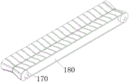
fig. 4 is a schematic perspective view of the connection structure of the first conveying roller and the first conveying belt of the present invention.
In the figure: 100. a crusher main body; 110. a crushing bin; 120. a feed hopper; 130. a crushing roller; 140. a gear; 150. a base plate; 160. a carriage; 170. a first conveying roller; 180. a first conveyor belt; 190. a control panel; 210. a servo motor; 220. a belt pulley transmission mechanism; 310. screening grids; 320. a reinforcing block; 330. a cam; 410. a second conveying roller; 420. a second conveyor belt.
The specific implementation mode is as follows:
the technical solutions in the embodiments of the present invention will be described clearly and completely with reference to the accompanying drawings in the embodiments of the present invention, and it is obvious that the described embodiments are only some embodiments of the present invention, not all embodiments. Based on the embodiments in the present invention, all other embodiments obtained by a person skilled in the art without creative work belong to the protection scope of the present invention.
Referring to fig. 1-4, the present invention provides an embodiment: an ore crusher with an automatic feeding mechanism comprises a crusher main body 100, wherein the crusher main body 100 comprises a crushing bin 110, a feed hopper 120 is fixedly welded at the top of the crushing bin 110, crushing rollers 130 are symmetrically and rotatably connected at the middle position inside the crushing bin 110, a gear 140 is fixedly welded at one end of the back of each group of the crushing rollers 130, teeth assembled on the outer walls of the two groups of the gears 140 are matched, a bottom plate 150 is fixedly welded at the left side of the bottom of the crushing bin 110, a conveying frame 160 is fixedly installed at the top of the bottom plate 150 in an inclined manner, one end of the top of the conveying frame 160 extends to the position right above the feed hopper 120, first conveying rollers 170 are rotatably connected at the inner parts of the left end and the right end of the conveying frame 160, a first conveying belt 180 is sleeved between the two groups of the first conveying rollers 170, the two groups of the first conveying rollers 170 are in transmission connection through the first conveying belts 180, the middle position of the top of the bottom plate 150 is fixedly provided with a control panel 190, the top of the bottom plate 150 is fixedly provided with a servo motor 210, a belt pulley transmission mechanism 220 is fixedly connected between a rotation output shaft of the servo motor 210 and one of the crushing rollers 130, the crushing rollers 130 are in transmission connection with the servo motor 210 through the belt pulley transmission mechanism 220, and teeth between the two groups of gears 140 are meshed with each other, so that when the device is used, under the driving of power, the two groups of gears 140 drive the two groups of crushing rollers 130 to rotate simultaneously and relatively, and the ore is crushed through the rotation of the crushing rollers 130, when the device is used, the first conveying roller 170 is driven by the power to drive the first conveying belt 180 sleeved on the outer side of the first conveying roller to rotate, the ore is conveyed upwards through the rotation of the first conveying belt 180, enters the crushing bin 110 through the feed hopper 120, and is crushed under the rotation action of the crushing rollers 130, the conveying frame 160 is fixed at the top of the bottom plate 150, so that the device is provided with a feeding conveying device, other external conveying devices are not required to be installed, the rapidity of the device in use is effectively guaranteed, the working efficiency of ore crushing is conveniently guaranteed, and the installation operation complexity of the ore crushing is effectively reduced;
furthermore, the top opening of the feeding hopper 120 is open, the top end of the feeding hopper 120 is inclined, the height of the left side of the top of the feeding hopper 120 is lower than the height of the right side of the top of the feeding hopper, and the right side of the feeding hopper 120 is higher, so that when the device is used, the outward falling of ores in the feeding process is effectively avoided under the blocking of the outer wall of the right side of the feeding hopper 120, and the feeding stability of the device is convenient to guarantee;
furthermore, the middle position of the first conveying roller 170 is concave, the diameter of the middle position of the first conveying roller 170 is smaller than the diameters of the front end position and the rear end position of the first conveying roller, convex strips are uniformly assembled on the outer surface of the first conveying belt 180, the middle position of the surface of the belt pulley transmission mechanism 220 is concave through the shape guide of the first conveying roller 170 when the device is used, the ore is prevented from falling outwards in the conveying process through the inclined guide of the two sides, the feeding stability of the device is effectively guaranteed, the convex strips are uniformly fixed on the outer surface of the first conveying belt 180, the fluctuation degree of the outer surface of the device is effectively increased through the convex strips, the frictional resistance between the ore and the first conveying belt 180 is effectively increased, and the slipping of the ore in the feeding process is conveniently prevented;
furthermore, the inside of the crushing bin 110 is fixedly provided with the sieve grids 310, the sieve grids 310 are located below the two groups of crushing rollers 130, the middle position of the sieve grids 310 is fixedly welded with the reinforcing block 320, the middle position of the inside of the crushing bin 110 is rotatably connected with the cam 330, the cam 330 is located right below the reinforcing block 320, the sieve grids 310 are fixedly arranged inside the crushing bin 110, the ore which is not completely crushed is continuously stopped above the sieve grids 310 to be continuously crushed through screening and blocking of the sieve grids 310, crushing integrity of the device is effectively guaranteed, meanwhile, the cam 330 is rotatably connected inside the crushing bin 110 through setting, the reinforcing block 320 is continuously and reciprocally knocked when the cam 330 rotates, the sieve grids 310 vibrate up and down, and screening efficiency of the sieve grids 310 on the crushed ore is effectively improved;
further, the left and right sides of the bottom of the crushing bin 110 are rotatably connected with second conveying rollers 410, the height of the left group of second conveying rollers 410 is higher than that of the right group of second conveying rollers 410, a second conveying belt 420 is sleeved between the two groups of second conveying rollers 410, the two groups of second conveying belts 420 are in transmission connection through the second conveying belts 420, by arranging the second conveying roller 410 and the second conveying belt 420 to be installed at the bottom position of the crushing bin 110, the second conveying belt 420 is rotated by the rotation of the second conveying roller 410, can effectively convey the crushed ore outwards, is convenient for ensuring the device to continuously and stably crush the ore, meanwhile, the positions of the left group of second conveying rollers 410 are higher than the positions of the right group of second conveying rollers 410, so that the ores are effectively prevented from sliding to the left side inside the crushing bin 110, and the crushed ores are prevented from being accumulated inside the crushing bin 110;
further, four sets of belt pulley transmission mechanisms 220 are provided, the four sets of belt pulley transmission mechanisms 220 are respectively and fixedly connected between the first conveying roller 170 and the rotation output shaft of the servo motor 210, between the crushing roller 130 and the rotation output shaft of the servo motor 210, between the second conveying roller 410 and the rotation output shaft of the servo motor 210, and between the second conveying roller 410 and the cam 330, the rotation output shaft of the servo motor 210 is respectively and drivingly connected to the crushing roller 130, the first conveying roller 170 and the second conveying roller 410 through the three sets of servo motors 210, and another set of servo motors 210 is provided to be drivingly connected between the second conveyor roller 410 and the cam 330, so that the device can be driven by only a single servo motor 210, effectively avoiding the waste of the rotation power of the servo motor 210, the using amount of the servo motor 210 is effectively reduced, and the production cost of the device is conveniently reduced;
the working principle is as follows: when the device works, a worker connects the device with an external power supply, so that the external power supply provides electric power support for the device, and then the worker can control the device to be powered on and started through the control panel 190;
when the device works, the device is powered on and started, the servo motor 210 drives the first conveying roller 170 to rotate through the belt pulley transmission mechanism 220, the first conveying belt 180 rolls upwards through the rotation of the first conveying roller 170, ores are continuously conveyed towards the upper right through the left end of the first conveying belt 180, so that the ores fall into the feed hopper 120, and the ores are prevented from falling out through the shielding of the right height of the feed hopper 120;
during operation, the servo motor 210 drives one of the crushing rollers 130 to rotate through the belt pulley transmission mechanism 220, the two groups of the crushing rollers 130 synchronously rotate in opposite directions through the meshing of teeth between the two groups of the gears 140, and rotationally crush the ore falling from the feed hopper 120, during the crushing process, the ore which is not completely crushed stops above the sieve lattice 310 due to the blocking of the sieve lattice 310, and the crushed ore falls downwards under the action of gravity;
the during operation, servo motor 210 drives second conveying roller 410 through belt pulley drive 220 and rotates for second conveying roller 410 is rotatory to drive second conveyer belt 420 and rotates, outwards carries the ore crushed aggregates that drops its top, and simultaneously, second conveying roller 410 drives cam 330 rotatory through another group belt pulley drive 220, and cam 330 reciprocates under the continuous rotation and moves reinforcing block 320, makes sieve check 310 vibrations that fluctuate, promotes sieve check 310's screening speed, above does the utility model discloses a whole theory of operation.
It is obvious to a person skilled in the art that the invention is not restricted to details of the above-described exemplary embodiments, but that it can be implemented in other specific forms without departing from the spirit or essential characteristics of the invention. The present embodiments are therefore to be considered in all respects as illustrative and not restrictive, the scope of the invention being indicated by the appended claims rather than by the foregoing description, and all changes which come within the meaning and range of equivalency of the claims are therefore intended to be embraced therein. Any reference sign in a claim should not be construed as limiting the claim concerned.
Claims (6)
1. A mineral breaker with automatic feed mechanism, includes breaker main part (100), its characterized in that: the crusher main body (100) comprises a crushing bin (110), a feed hopper (120) is fixedly welded at the top of the crushing bin (110), the crushing rollers (130) are symmetrically and rotatably connected to the middle position inside the crushing bin (110), gears (140) are fixedly welded at one end of the back face of each crushing roller (130), the two groups of gears are matched with teeth assembled on the outer wall of each gear (140), a bottom plate (150) is fixedly welded at the left side of the bottom of the crushing bin (110), a conveying frame (160) is fixedly installed at the top of the bottom plate (150), the conveying frame (160) is fixedly installed at the top of the bottom plate (150) in an inclined manner, one end of the top of the conveying frame (160) extends to the position right above the feed hopper (120), first conveying rollers (170) are rotatably connected to the inner portions of the left end and the right end of the conveying frame (160), and a first conveying belt (180) is sleeved between the two groups of the first conveying rollers (170), the two groups of first conveying rollers (170) are in transmission connection through first conveying belts (180), a control panel (190) is fixedly mounted at the middle position of the top of the bottom plate (150), a servo motor (210) is fixedly mounted at the top of the bottom plate (150), a belt pulley transmission mechanism (220) is fixedly connected between a rotating output shaft of the servo motor (210) and one of the groups of crushing rollers (130), and the crushing rollers (130) are in transmission connection with the servo motor (210) through the belt pulley transmission mechanism (220).
2. A mineral breaker having an automatic feed mechanism in accordance with claim 1 wherein: the open-top of feeder hopper (120) is for opening the form, the top of feeder hopper (120) is the slope form, the top left side height of feeder hopper (120) is less than its top right side height.
3. A mineral breaker having an automatic feed mechanism in accordance with claim 1 wherein: the middle position of the first conveying roller (170) is concave, the diameter of the middle position of the first conveying roller (170) is smaller than the diameters of the front end position and the rear end position of the first conveying roller, and convex strips are uniformly assembled on the outer surface of the first conveying belt (180).
4. A mineral breaker having an automatic feed mechanism in accordance with claim 1 wherein: the inside fixed mounting in crushing storehouse (110) has sieve check (310), and sieve check (310) are located two sets of the below position of crushing roller (130), the fixed welding of the intermediate position of sieve check (310) has reinforcing block (320), the inside intermediate position of crushing storehouse (110) rotates and is connected with cam (330), and cam (330) are located reinforcing block (320) under.
5. A mineral breaker having an automatic feed mechanism in accordance with claim 4 wherein: the left side and the right side of the bottom of the crushing bin (110) are rotatably connected with second conveying rollers (410), the height of the second conveying rollers (410) on the left side is higher than that of the second conveying rollers (410) on the right side, a second conveying belt (420) is sleeved between the two groups of second conveying rollers (410), and the two groups of second conveying belts (420) are in transmission connection through the second conveying belts (420).
6. A mineral breaker having an automatic feed mechanism in accordance with claim 5 wherein: the belt pulley transmission mechanisms (220) are provided with four groups, and the four groups of belt pulley transmission mechanisms (220) are respectively and fixedly connected between the first conveying roller (170) and the rotating output shaft of the servo motor (210), between the crushing roller (130) and the rotating output shaft of the servo motor (210), between the second conveying roller (410) and the rotating output shaft of the servo motor (210), and between the second conveying roller (410) and the cam (330).
Priority Applications (1)
| Application Number | Priority Date | Filing Date | Title |
|---|---|---|---|
| CN202022417688.7U CN213791868U (en) | 2020-10-27 | 2020-10-27 | Ore crusher with automatic feeding mechanism |
Applications Claiming Priority (1)
| Application Number | Priority Date | Filing Date | Title |
|---|---|---|---|
| CN202022417688.7U CN213791868U (en) | 2020-10-27 | 2020-10-27 | Ore crusher with automatic feeding mechanism |
Publications (1)
| Publication Number | Publication Date |
|---|---|
| CN213791868U true CN213791868U (en) | 2021-07-27 |
Family
ID=76961937
Family Applications (1)
| Application Number | Title | Priority Date | Filing Date |
|---|---|---|---|
| CN202022417688.7U Expired - Fee Related CN213791868U (en) | 2020-10-27 | 2020-10-27 | Ore crusher with automatic feeding mechanism |
Country Status (1)
| Country | Link |
|---|---|
| CN (1) | CN213791868U (en) |
Cited By (2)
| Publication number | Priority date | Publication date | Assignee | Title |
|---|---|---|---|---|
| CN116116587A (en) * | 2023-02-06 | 2023-05-16 | 重庆三体应用技术研究院有限公司 | High-efficient separator of copper zinc sulphide ore deposit |
| CN116218591A (en) * | 2023-04-17 | 2023-06-06 | 广州市基优源食品有限公司 | Animal fat low-temperature extraction equipment and process |
-
2020
- 2020-10-27 CN CN202022417688.7U patent/CN213791868U/en not_active Expired - Fee Related
Cited By (3)
| Publication number | Priority date | Publication date | Assignee | Title |
|---|---|---|---|---|
| CN116116587A (en) * | 2023-02-06 | 2023-05-16 | 重庆三体应用技术研究院有限公司 | High-efficient separator of copper zinc sulphide ore deposit |
| CN116116587B (en) * | 2023-02-06 | 2024-04-26 | 新疆哈巴河阿舍勒铜业股份有限公司 | High-efficient separator of copper zinc sulphide ore deposit |
| CN116218591A (en) * | 2023-04-17 | 2023-06-06 | 广州市基优源食品有限公司 | Animal fat low-temperature extraction equipment and process |
Similar Documents
| Publication | Publication Date | Title |
|---|---|---|
| CN213791868U (en) | Ore crusher with automatic feeding mechanism | |
| CN111497017A (en) | Building mortar charging equipment | |
| CN215087633U (en) | High-efficient rubbing crusher is used in biological medicine production | |
| CN206613596U (en) | A kind of anti-blockage type ore milling device | |
| CN209917975U (en) | Feeding mechanism of jigging coal washer | |
| CN214021064U (en) | Effectual crushing and screening device | |
| CN216654725U (en) | Be used for broken conveyor of ore | |
| CN211337731U (en) | Plate type feeding machine with crushing structure | |
| CN112875342B (en) | Take hoisting equipment for coal mine of long distance transport and branch sieve function | |
| CN212948423U (en) | Automatic ceramic grinding machine of material loading | |
| CN211362922U (en) | Recycled concrete aggregate feeding mechanism of mixing plant | |
| CN212284154U (en) | Ore breaker for mining | |
| CN115155770A (en) | Automatic broken categorised recovery unit of green construction rubbish | |
| CN211887102U (en) | A reducing mechanism for ore crushing | |
| CN217862299U (en) | Waste rubber fine crushing recovery device | |
| CN217410889U (en) | Automatic crushing device for limestone mining | |
| CN220803688U (en) | Stone crushing and screening equipment for mine engineering | |
| CN221360433U (en) | Charging mechanism for beneficiation reagent raw materials | |
| CN221133085U (en) | Feeding device for sand and stone processing | |
| CN221016527U (en) | Feeding mechanism of coal screening box | |
| CN212702072U (en) | Feeding mechanism for anhydrous stemming forming machine | |
| CN217042792U (en) | Coal stone breaker for coal mine | |
| CN214266097U (en) | Novel preparation of environmental protection brick device | |
| CN216224587U (en) | Glass substrate recovery device | |
| CN211470108U (en) | Raw material elevator is used in carbon brick production |
Legal Events
| Date | Code | Title | Description |
|---|---|---|---|
| GR01 | Patent grant | ||
| GR01 | Patent grant | ||
| PE01 | Entry into force of the registration of the contract for pledge of patent right | ||
| PE01 | Entry into force of the registration of the contract for pledge of patent right |
Denomination of utility model: Ore crusher with automatic feeding mechanism Effective date of registration: 20210916 Granted publication date: 20210727 Pledgee: Qishang Bank Co.,Ltd. Boshan sub branch Pledgor: Shandong Yuqi Heavy Industry Co.,Ltd. Registration number: Y2021980009443 |
|
| CF01 | Termination of patent right due to non-payment of annual fee | ||
| CF01 | Termination of patent right due to non-payment of annual fee |
Granted publication date: 20210727 |