CN213791808U - Movable cone crushing mechanism of ore machine - Google Patents
Movable cone crushing mechanism of ore machine Download PDFInfo
- Publication number
- CN213791808U CN213791808U CN202021390013.1U CN202021390013U CN213791808U CN 213791808 U CN213791808 U CN 213791808U CN 202021390013 U CN202021390013 U CN 202021390013U CN 213791808 U CN213791808 U CN 213791808U
- Authority
- CN
- China
- Prior art keywords
- organism
- frame
- fixed connection
- connection
- movable
- Prior art date
- Legal status (The legal status is an assumption and is not a legal conclusion. Google has not performed a legal analysis and makes no representation as to the accuracy of the status listed.)
- Active
Links
Images

Landscapes
- Crushing And Grinding (AREA)
Abstract
The utility model discloses a broken mechanism of movable cone of ore deposit relates to movable cone breaker technical field, for the unable problem of adjusting of the ordinary broken degree of movable cone breaker among the solution prior art. The internally mounted of organism has the feeder hopper, feeder hopper and organism fixed connection, the internally mounted of organism has the movable to roll the mortar wall, the movable is rolled the inner wall laminating of mortar wall and organism, the internally mounted of organism has the second hydraulic pressure top, organism and movable roll the mortar wall all with second hydraulic pressure top fixed connection, the internally mounted of frame has eccentric cover, eccentric cover and frame fixed connection, the internally mounted of eccentric cover has the main shaft, the main shaft rotates with eccentric cover to be connected.
Description
Technical Field
The utility model relates to a moving cone breaker technical field specifically is a broken mechanism of moving cone of ore deposit machine.
Background
The movable cone crusher is also called cone crusher, and is a crushing machine suitable for raw materials in the industries of metallurgy, building, road building, chemistry and silicate, and is divided into a plurality of models according to different crushing principles and different product particle sizes.
With the continuous development of mine technology, cone crushers are also divided into a plurality of types, including 4 types of spring cone crushers, rolling mortar cone crushers, hydraulic cone crushers and composite cone crushers according to the types, but the crushing degree of the inner part of any type of cone crusher is constant, the crushing degree of the cone crusher cannot be adjusted, and when the crushed stone needs to be crushed more finely, the cone crusher can be replaced by a more detailed movable cone crusher, so that the efficiency of crushing the crushed stone in industrial production is reduced; therefore, the market urgently needs to develop a movable cone crushing mechanism of an ore machine to help people to solve the existing problems.
SUMMERY OF THE UTILITY MODEL
An object of the utility model is to provide a broken mechanism of moving cone of ore deposit to solve the problem that the unable regulation of the broken degree of the ordinary moving cone breaker that proposes among the above-mentioned background art.
In order to achieve the above object, the utility model provides a following technical scheme: the utility model provides a broken mechanism of movable cone of ore deposit, includes organism and frame, the internally mounted of organism has the feeder hopper, feeder hopper and organism fixed connection, the internally mounted of organism has the movable to roll the mortar wall, the movable inner wall laminating of rolling mortar wall and organism, the internally mounted of organism has the second hydraulic pressure top, organism and movable roll the mortar wall all with second hydraulic pressure top fixed connection.
Preferably, the inside of frame is installed with eccentric cover, eccentric cover and frame fixed connection, the internally mounted of eccentric cover has the main shaft, the main shaft rotates with eccentric cover to be connected.
Preferably, the outside of main shaft is installed respectively and is moved cone and driven gear, it all with main shaft fixed connection to move cone and driven gear, the internally mounted of frame has the transmission shaft, the frame rotates with the transmission shaft to be connected, drive gear and belt pulley are installed respectively to the both ends of transmission shaft, drive gear and belt pulley all with transmission shaft fixed connection, drive gear is connected with the driven gear interlock.
Preferably, the base is installed to the below of frame, base and frame fixed connection, the cantilever is installed in the outside of organism, cantilever and organism fixed connection.
Preferably, a first hydraulic ram is installed above the base, and the base and the cantilever are both fixedly connected with the first hydraulic ram.
Preferably, the outside of organism is provided with first connecting leg, first connecting leg sets up structure as an organic whole with the organism, the outside of frame is provided with the second and connects the leg, the second is connected the leg and is set up structure as an organic whole with the frame, spring and connecting rod are installed respectively to the top of second connection leg, spring and connecting rod all are connected leg fixed connection with the second, spring and first connecting leg fixed connection, connecting rod and first connecting leg sliding connection, the stopper is installed to the top of first connection leg, stopper and first connecting leg threaded connection.
Compared with the prior art, the beneficial effects of the utility model are that:
1. the utility model discloses a through the setting on movable rolling mortar wall and second hydraulic pressure top, through movable rolling mortar wall and second hydraulic pressure top at the internally mounted movable of moving cone breaker, when needs more careful broken rubble, push up movable rolling mortar wall through second hydraulic pressure top and remove to the inboard of organism, thereby reach and reduce movable rolling mortar wall and move the clearance effect between the cone, thereby when the rubble through movable rolling mortar wall and move the extrusion breakage between the cone, crushing degree is higher, thereby realize moving cone breaker crushing degree adjustable function effect, the efficiency of the broken rubble of improvement industrial production.
2. The utility model discloses a through the setting of first hydraulic ram and cantilever, when the inside entering of moving cone breaker is bulky and unable broken ore, it is ascending to push up the cantilever through first hydraulic ram to rise the organism, thereby increase movable and roll mortar wall and move the clearance between the cone, thereby directly fall the ore, thereby prevent that too hard bulky rubble from damaging the breaker, improved the life of breaker.
Drawings
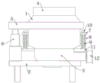
Fig. 1 is a front view of a movable cone crushing mechanism of an ore machine according to the present invention;
fig. 2 is a schematic internal structural diagram of a movable cone crushing mechanism of an ore machine according to the present invention;
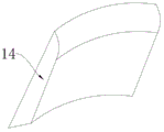
fig. 3 is an overall schematic view of the movable rolling mortar wall of the present invention.
In the figure: 1. a body; 2. a base; 3. a frame; 4. a feed hopper; 5. a cantilever; 6. a first hydraulic ram; 7. a first connecting leg; 8. a spring; 9. a connecting rod; 10. a limiting block; 11. a second connecting leg; 12. a belt pulley; 13. a movable cone; 14. a movable rolling mortar wall; 15. a second hydraulic ram; 16. a main shaft; 17. an eccentric sleeve; 18. a driven gear; 19. a drive gear; 20. a drive shaft.
Detailed Description
The technical solutions in the embodiments of the present invention will be described clearly and completely with reference to the accompanying drawings in the embodiments of the present invention, and it is obvious that the described embodiments are only some embodiments of the present invention, not all embodiments.
Referring to fig. 1-3, the present invention provides an embodiment: the utility model provides a broken mechanism of movable cone of ore deposit, includes organism 1 and frame 3, and the internally mounted of organism 1 has feeder hopper 4, feeder hopper 4 and 1 fixed connection of organism, and the internally mounted of organism 1 has movable to roll mortar wall 14, and movable rolls mortar wall 14 and the inner wall laminating of organism 1, and the internally mounted of organism 1 has second hydraulic pressure top 15, and organism 1 and movable roll mortar wall 14 all with second hydraulic pressure top 15 fixed connection.
Further, an eccentric sleeve 17 is installed inside the frame 3, the eccentric sleeve 17 is fixedly connected with the frame 3, a main shaft 16 is installed inside the eccentric sleeve 17, the main shaft 16 is rotatably connected with the eccentric sleeve 17, and the main shaft 16 is also an eccentric shaft.
Further, the outer side of the main shaft 16 is provided with a movable cone 13 and a driven gear 18 respectively, the movable cone 13 and the driven gear 18 are fixedly connected with the main shaft 16, the inside of the frame 3 is provided with a transmission shaft 20, the frame 3 is rotatably connected with the transmission shaft 20, two ends of the transmission shaft 20 are provided with a driving gear 19 and a belt pulley 12 respectively, the driving gear 19 and the belt pulley 12 are fixedly connected with the transmission shaft 20, the driving gear 19 is meshed with the driven gear 18, and a material distributing disc is arranged above the movable cone 13 and has a material guiding function.
Further, base 2 is installed to the below of frame 3, base 2 and frame 3 fixed connection, and cantilever 5 is installed in the outside of organism 1, and cantilever 5 and organism 1 fixed connection, the below of frame 3 are provided with the discharge gate, and the rubble after the breakage passes through the discharge gate and discharges.
Further, first hydraulic ram 6 is installed to the top of base 2, and base 2 and cantilever 5 all with first hydraulic ram 6 fixed connection, the junction of cantilever 5 and first hydraulic ram 6 can rotate simultaneously.
Further, the outside of organism 1 is provided with first connection leg 7, first connection leg 7 sets up to a body structure with organism 1, the outside of frame 3 is provided with second connection leg 11, second connection leg 11 sets up to a body structure with frame 3, spring 8 and connecting rod 9 are installed respectively to the top of second connection leg 11, spring 8 and connecting rod 9 all are connected leg 11 fixed connection with the second, spring 8 and first connection leg 7 fixed connection, connecting rod 9 and first connection leg 7 sliding connection, stopper 10 is installed to the top of first connection leg 7, stopper 10 and 7 threaded connection of first connection leg, first connection leg 7, spring 8, second connection leg 11, connecting rod 9 and stopper 10 are provided with a plurality of.
The working principle is as follows: when in use, crushed stones enter the inside of the crusher through the feed hopper 4, the belt pulley 12 is driven to rotate through the motor, the belt pulley 12 can drive the driving gear 19 to rotate through the transmission shaft 20, the driving gear 19 enables the driven gear 18 to rotate, so that the main shaft 16 rotates inside the eccentric sleeve 17, so that the main shaft 16 generates eccentric rotation, so that the movable cone 13 generates eccentric rotation, so that the gap between the movable cone 13 and the movable rolling mortar wall 14 and the immovable rolling mortar wall is small, the crushed stones are extruded and crushed when passing through a small gap, then fall into the inside of the frame 3 through a large gap and are discharged through the discharge port, when the crushing degree needs to be adjusted, the second hydraulic jack is started, so that the movable rolling mortar wall 14 moves towards the inner side of the machine body 1, and the gap between the movable rolling mortar wall 14 and the movable cone 13 is reduced, when the broken stone passes through the gap between the movable rolling mortar wall 14 and the movable cone 13, the broken stone is more finely broken, so that the fine breaking effect is achieved.
It is obvious to a person skilled in the art that the invention is not restricted to details of the above-described exemplary embodiments, but that it can be implemented in other specific forms without departing from the spirit or essential characteristics of the invention. The present embodiments are therefore to be considered in all respects as illustrative and not restrictive, the scope of the invention being indicated by the appended claims rather than by the foregoing description, and all changes which come within the meaning and range of equivalency of the claims are therefore intended to be embraced therein. Any reference sign in a claim should not be construed as limiting the claim concerned.
Claims (6)
1. The utility model provides a broken mechanism of mantle of ore deposit, includes organism (1) and frame (3), its characterized in that: the internally mounted of organism (1) has feeder hopper (4), feeder hopper (4) and organism (1) fixed connection, the internally mounted of organism (1) has movable to roll mortar wall (14), movable rolls the inner wall laminating of mortar wall (14) and organism (1), the internally mounted of organism (1) has second hydraulic pressure top (15), organism (1) and movable roll mortar wall (14) all with second hydraulic pressure top (15) fixed connection.
2. A moving cone crushing mechanism for a mining machine as claimed in claim 1, wherein: the utility model discloses a motor, including frame (3), the internally mounted of frame (3) has eccentric cover (17), eccentric cover (17) and frame (3) fixed connection, the internally mounted of eccentric cover (17) has main shaft (16), main shaft (16) are connected with eccentric cover (17) rotation.
3. A moving cone crushing mechanism for a mining machine as claimed in claim 2, wherein: the utility model discloses a drive gear, including main shaft (16), frame (3), drive gear (19) and belt pulley (12), the outside of main shaft (16) is installed respectively and is moved cone (13) and driven gear (18), move cone (13) and driven gear (18) all with main shaft (16) fixed connection, the internally mounted of frame (3) has transmission shaft (20), frame (3) rotate with transmission shaft (20) and are connected, drive gear (19) and belt pulley (12) are installed respectively to the both ends of transmission shaft (20), drive gear (19) and belt pulley (12) all with transmission shaft (20) fixed connection, drive gear (19) are connected with driven gear (18) interlock.
4. A moving cone crushing mechanism for a mining machine as claimed in claim 1, wherein: base (2) are installed to the below of frame (3), base (2) and frame (3) fixed connection, cantilever (5) are installed in the outside of organism (1), cantilever (5) and organism (1) fixed connection.
5. A moving cone crushing mechanism for a mining machine as claimed in claim 4, wherein: first hydraulic ram (6) are installed to the top of base (2), base (2) and cantilever (5) all with first hydraulic ram (6) fixed connection.
6. A moving cone crushing mechanism for a mining machine as claimed in claim 1, wherein: the outside of organism (1) is provided with first connection leg (7), first connection leg (7) set up structure as an organic whole with organism (1), the outside of frame (3) is provided with second connection leg (11), second connection leg (11) set up structure as an organic whole with frame (3), spring (8) and connecting rod (9) are installed respectively to the top of second connection leg (11), spring (8) and connecting rod (9) all are connected leg (11) fixed connection with the second, spring (8) and first connection leg (7) fixed connection, connecting rod (9) and first connection leg (7) sliding connection, stopper (10) are installed to the top of first connection leg (7), stopper (10) and first connection leg (7) threaded connection.
Priority Applications (1)
| Application Number | Priority Date | Filing Date | Title |
|---|---|---|---|
| CN202021390013.1U CN213791808U (en) | 2020-07-15 | 2020-07-15 | Movable cone crushing mechanism of ore machine |
Applications Claiming Priority (1)
| Application Number | Priority Date | Filing Date | Title |
|---|---|---|---|
| CN202021390013.1U CN213791808U (en) | 2020-07-15 | 2020-07-15 | Movable cone crushing mechanism of ore machine |
Publications (1)
| Publication Number | Publication Date |
|---|---|
| CN213791808U true CN213791808U (en) | 2021-07-27 |
Family
ID=76930846
Family Applications (1)
| Application Number | Title | Priority Date | Filing Date |
|---|---|---|---|
| CN202021390013.1U Active CN213791808U (en) | 2020-07-15 | 2020-07-15 | Movable cone crushing mechanism of ore machine |
Country Status (1)
| Country | Link |
|---|---|
| CN (1) | CN213791808U (en) |
Cited By (2)
| Publication number | Priority date | Publication date | Assignee | Title |
|---|---|---|---|---|
| CN113856801A (en) * | 2021-09-09 | 2021-12-31 | 浙江武精机器制造有限公司 | Cone crusher with controllable forced-disengaging area |
| CN113996377A (en) * | 2021-10-25 | 2022-02-01 | 浙江秦核环境建设有限公司 | Mineral breaker |
-
2020
- 2020-07-15 CN CN202021390013.1U patent/CN213791808U/en active Active
Cited By (3)
| Publication number | Priority date | Publication date | Assignee | Title |
|---|---|---|---|---|
| CN113856801A (en) * | 2021-09-09 | 2021-12-31 | 浙江武精机器制造有限公司 | Cone crusher with controllable forced-disengaging area |
| CN113856801B (en) * | 2021-09-09 | 2023-01-10 | 浙江武精机器制造有限公司 | Cone crusher with controllable forced-disengaging area |
| CN113996377A (en) * | 2021-10-25 | 2022-02-01 | 浙江秦核环境建设有限公司 | Mineral breaker |
Similar Documents
| Publication | Publication Date | Title |
|---|---|---|
| CN206064585U (en) | A kind of optional colliery of broken thickness is layered disintegrating machine | |
| CN213791808U (en) | Movable cone crushing mechanism of ore machine | |
| CN201625547U (en) | Novel roller-type breaker | |
| CN206082780U (en) | There is not colliery layering feeding breaker of handling earlier stage | |
| CN107377089A (en) | A kind of environmentally friendly ore efficiency crushing device | |
| CN201316661Y (en) | Novel structure-hydraulic spring rolling mill with breaking prior to milling | |
| CN206560882U (en) | A kind of mineral breaker that multistage can continuously crush | |
| CN103752370A (en) | Energy-saving roller type grading machine | |
| CN202590848U (en) | Crusher for high-strength banded goods | |
| CN110052305B (en) | Crusher capable of efficiently crushing and easily blanking | |
| CN212732380U (en) | Vertical superfine powder roller mill with material conveying channel | |
| CN210646569U (en) | Pottery garbage collection device | |
| CN217288615U (en) | Tooth roller type jaw crusher | |
| CN205868370U (en) | Two -way ore crushing apparatus that rolls | |
| CN212215671U (en) | Cement manufacture grog breaker | |
| CN102284320B (en) | Vertical grinding roller sand making machine | |
| CN202212215U (en) | Hydraulic double-roll crushing mill | |
| CN210332806U (en) | Multi-functional novel wear-resisting material breaker | |
| CN211677914U (en) | Novel equal-gap shaping crusher device | |
| CN101455988B (en) | Micro-controlled hydraulic fine breaking device | |
| CN2411057Y (en) | double-acting jaws high energy crushing mechanism | |
| CN112246339A (en) | Adjustable single-roller crusher | |
| CN206911441U (en) | The compound kibbler roll of hydraulic pressure | |
| CN2430218Y (en) | Soil crusher | |
| CN206229432U (en) | Double-geared roller crusher |
Legal Events
| Date | Code | Title | Description |
|---|---|---|---|
| GR01 | Patent grant | ||
| GR01 | Patent grant |