CN213782311U - Straight-head electric connector - Google Patents
Straight-head electric connector Download PDFInfo
- Publication number
- CN213782311U CN213782311U CN202023279811.XU CN202023279811U CN213782311U CN 213782311 U CN213782311 U CN 213782311U CN 202023279811 U CN202023279811 U CN 202023279811U CN 213782311 U CN213782311 U CN 213782311U
- Authority
- CN
- China
- Prior art keywords
- straight
- connecting shell
- electrical connector
- cavity
- shell
- Prior art date
- Legal status (The legal status is an assumption and is not a legal conclusion. Google has not performed a legal analysis and makes no representation as to the accuracy of the status listed.)
- Active
Links
Images


Abstract
The utility model relates to the technical field of connectors, in particular to a straight-head electric connector, which comprises a connecting shell and a splicing cavity arranged on the connecting shell, wherein the splicing cavity is used for splicing a connector; the second connecting assembly comprises an alloy seat, an insulator arranged on the inner diameter of the alloy seat and a plug terminal inserted in the insulator, wherein the alloy seat is fixedly arranged on the connecting shell and extends to the plug cavity; the utility model discloses can realize two kinds of transmission connection on a connector shell, simple structure, it is convenient to connect, and the practicality is strong.
Description
Technical Field
The utility model relates to a connector technical field especially relates to a straight head electric connector.
Background
A connector is a component that is frequently contacted by an electrical engineering technician. The function is as follows: a bridge for communication is erected between the blocked part or isolated and non-communicated circuits in the circuit, so that current flows, and the circuit achieves the preset function. Connectors are indispensable components in electronic devices, and one or more connectors are always found by observing a current flowing path. The connector forms and structures are widely varied, and there are various types of connectors depending on the application, frequency, power, application environment, and the like.
Connectors are now widely used in various industries and there are great uses and benefits to connectors, such as: the connector is improved in the production process, and the assembly process of the electronic product is simplified; the mass production process is also simplified. The existing connector can only carry out data transmission or power transmission independently in connection and use, and particularly in an automobile connector, the occupied area is large, the structure is complex, and the cost is high.
SUMMERY OF THE UTILITY MODEL
In order to solve the above problem, the utility model provides a can realize two kinds of transmission connection on a connector housing, simple structure, it is convenient to connect, straight first electric connector that the practicality is strong.
The utility model adopts the technical proposal that: a straight-head electric connector comprises a connecting shell, an inserting cavity arranged on the connecting shell and used for inserting the connector, and a first connecting assembly inserted in the connecting shell and extending to the inserting cavity; the second connecting assembly comprises an alloy seat, an insulator arranged on the inner diameter of the alloy seat and a plug terminal inserted in the insulator, wherein the alloy seat is fixedly arranged on the connecting shell and extends to the plug cavity.
The further improvement of the scheme is that the connecting shell is integrally formed by injection molding, and the inserting cavity is integrally formed in the connecting shell.
The further improvement of the scheme is that the connecting shell is provided with an inserting positioning groove above the connecting shell, and the inserting positioning groove is communicated to the inserting cavity.
The further improvement of the scheme is that one end of the connecting shell, which deviates from the inserting cavity, is provided with a first fixing groove and a second fixing groove, the first connecting assembly is inserted into the first fixing groove, and the second connecting assembly is fixed on the second fixing groove.
The further improvement of the scheme is that a plurality of bosses are integrally formed on the outer edge of one end, deviating from the inserting cavity, of the connecting shell.
The scheme is further improved in that the two sides of the inserting cavity are provided with inserting positioning steps.
In a further improvement of the above solution, the first connecting assembly includes at least two sets of electrical terminals.
The further improvement of the scheme is that the alloy seat is a zinc alloy seat and comprises a fixed end fixedly connected with the connecting shell, an inserting end extending into the inserting cavity and a through hole which is arranged in the middle and penetrates through the fixed end and the connecting end.
In a further improvement of the above solution, the insulator is fixed in the through hole.
In a further improvement of the above arrangement, the mating terminal is centrally fixed in the insulator and extends into the mating end.
The utility model has the advantages that:
compared with the traditional connector, the utility model discloses a first connecting elements and second coupling assembling have been set up to the structure of directly starting to the structure on the connection shell of directly starting to the structure, can realize two kinds of transmission connection on a connector shell, and first connecting elements is connected for the power, and second coupling assembling is the data transmission connection, simple structure, and convenient connection, the practicality is strong. The connector comprises a connecting shell, an inserting cavity arranged on the connecting shell, a first connecting assembly and a second connecting assembly, wherein the inserting cavity is used for inserting a connector; the second connecting assembly comprises an alloy seat, an insulator arranged on the inner diameter of the alloy seat and a plug terminal inserted in the insulator, wherein the alloy seat is fixedly arranged on the connecting shell and extends to the plug cavity; the second connecting assembly is connected with the transmission through the alloy seat acting structure, and the insulator acts on the insulation between the plug terminal and the alloy seat, so that the plug is convenient to plug.
Drawings
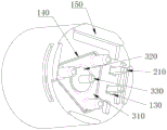
Fig. 1 is a schematic perspective view of the present invention;
fig. 2 is a schematic perspective view of another perspective of the present invention;
fig. 3 is a schematic top view of the present invention;
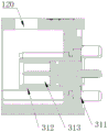
fig. 4 is a cross-sectional view a-a of fig. 3.
Description of reference numerals: the connector comprises a connector housing 100, a plug cavity 110, a plug positioning step 111, a plug positioning groove 120, a first fixing groove 130, a second fixing groove 140, a boss 150, a first connecting assembly 200, an electric terminal 210, a second connecting assembly 300, an alloy base 310, a fixing end 311, a plug end 312, a through hole 313, an insulator 320 and a plug terminal 330.
Detailed Description
The present invention will be further described with reference to the accompanying drawings.
As shown in fig. 1 to 4, a straight electrical connector includes a connecting housing 100, a plugging cavity 110 opened in the connecting housing 100, the plugging cavity 110 being used for plugging a connector, a first connecting element 200 inserted in the connecting housing 100 and extending to the plugging cavity 110; the second connection assembly 300 includes an alloy base 310, an insulator 320 installed in an inner diameter of the alloy base 310, and a plug terminal 330 inserted into the insulator 320, wherein the alloy base 310 is fixedly installed in the connection housing 100 and extends to the plug cavity 110.
Connect shell 100 for integrative injection moulding, grafting chamber 110 integrated into one piece in connecting shell 100, adopt integrative injection moulding's connection shell 100 structure, use intensity is high, and wholeness is strong.
The connection housing 100 is provided with an insertion positioning groove 120 above the connection housing 100, the insertion positioning groove 120 is communicated to the insertion cavity 110, and the insertion positioning groove 120 facilitates the insertion and fixation of the connector, thereby ensuring the insertion stability.
Connect shell 100 and deviate from grafting chamber 110 one end and seted up first fixed slot 130 and second fixed slot 140, first coupling assembling 200 is inserted and is located first fixed slot 130, second coupling assembling 300 is fixed in second fixed slot 140, and it is fixed to be used for grafting of first coupling assembling 200 through first fixed slot 130, and second fixed slot 140 is used for second coupling assembling 300 fixed connection, connects conveniently, and is fixed effectual.
The outer edge of the end of the connection housing 100 away from the plugging cavity 110 is integrally formed with a plurality of bosses 150, and the bosses 150 can support the connector in a suspension manner when the connector is mounted, and do not need to be completely attached.
The two sides of the plugging cavity 110 are provided with plugging positioning steps 111, corresponding plugging of the structure is facilitated through the plugging positioning steps 111, the plugging is convenient, and the plugging precision is high.
The first connection assembly 200 includes at least two sets of electrical terminals 210 through which the electrical terminals 210 are used for electrical transmission.
The alloy seat 310 is a zinc alloy seat 310, and includes a fixed end 311 fixedly connected to the connection housing 100, a plugging end 312 extending into the plugging cavity 110, and a through hole 313 centrally disposed through the fixed end 311 and the connection end, the plugging cavity 110 is used for connection plugging conductive transmission through the fixed end 311, the through hole 313 is used for fixing the insulator 320, the insulator 320 is fixed in the through hole 313, and the plugging end 312 is centrally disposed in the insulator 320 and extends into the plugging end 312, thereby facilitating conductive transmission.
The utility model discloses a first connecting component 200 and second coupling assembling 300 have been set up to the structure of directly starting to end on the connection shell 100 of structure of directly starting to end, can realize two kinds of transmission connections on a connector shell, and first connecting component 200 is connected for the power, and second coupling assembling 300 is connected for data transmission, simple structure, and convenient the connection, the practicality is strong. The connector comprises a connecting shell 100, a plugging cavity 110 arranged on the connecting shell 100, a first connecting assembly 200 and a second connecting assembly, wherein the plugging cavity 110 is used for plugging a connector, and the first connecting assembly is plugged in the connecting shell 100 and extends to the plugging cavity 110; the second connection assembly 300 includes an alloy base 310, an insulator 320 installed in the inner diameter of the alloy base 310, and a plug terminal 312 inserted into the insulator 320, wherein the alloy base 310 is fixedly installed in the connection housing 100 and extends to the plug cavity 110; the second connecting component 300 is connected in a transmission mode through the alloy base 310, and the insulator 320 is used for insulating the inserting terminal 312 and the alloy base 310, so that the inserting is convenient.
The above-mentioned embodiments only represent some embodiments of the present invention, and the description thereof is specific and detailed, but not to be construed as limiting the scope of the present invention. It should be noted that, for those skilled in the art, without departing from the spirit of the present invention, several variations and modifications can be made, which are within the scope of the present invention. Therefore, the protection scope of the present invention should be subject to the appended claims.
Claims (10)
1. A straight electrical connector, comprising: comprises that
A connecting shell, an inserting cavity arranged on the connecting shell and used for inserting the connector,
the first connecting assembly is inserted into the connecting shell and extends to the inserting cavity;
the second connecting assembly comprises an alloy seat, an insulator arranged on the inner diameter of the alloy seat and a plug terminal inserted in the insulator, wherein the alloy seat is fixedly arranged on the connecting shell and extends to the plug cavity.
2. The straight-head electrical connector of claim 1, wherein: the connecting shell is formed by injection molding, and the inserting cavity is formed in the connecting shell in an integrated mode.
3. The straight-head electrical connector of claim 1, wherein: the connecting shell is provided with an inserting positioning groove above the connecting shell, and the inserting positioning groove is communicated to the inserting cavity.
4. The straight-head electrical connector of claim 1, wherein: connect the shell and deviate from grafting chamber one end and seted up first fixed slot and second fixed slot, first coupling assembling inserts and locates first fixed slot, second coupling assembling is fixed in the second fixed slot.
5. The straight-head electrical connector of claim 1, wherein: the outer edge of one end of the connecting shell, which is far away from the inserting cavity, is integrally formed with a plurality of bosses.
6. The straight-head electrical connector of claim 1, wherein: and the two sides of the inserting cavity are provided with inserting positioning steps.
7. The straight-head electrical connector of claim 1, wherein: the first connecting assembly comprises at least two groups of electric terminals.
8. The straight-head electrical connector of claim 1, wherein: the alloy seat is a zinc alloy seat and comprises a fixed end fixedly connected with the connecting shell, an inserting end extending into the inserting cavity and a through hole which is arranged in the middle and penetrates through the fixed end and the connecting end.
9. The straight-head electrical connector of claim 8, wherein: the insulator is fixed in the through hole.
10. The straight-head electrical connector of claim 9, wherein: the plug terminal is centrally fixed in the insulator and extends into the plug end.
Priority Applications (1)
| Application Number | Priority Date | Filing Date | Title |
|---|---|---|---|
| CN202023279811.XU CN213782311U (en) | 2020-12-29 | 2020-12-29 | Straight-head electric connector |
Applications Claiming Priority (1)
| Application Number | Priority Date | Filing Date | Title |
|---|---|---|---|
| CN202023279811.XU CN213782311U (en) | 2020-12-29 | 2020-12-29 | Straight-head electric connector |
Publications (1)
| Publication Number | Publication Date |
|---|---|
| CN213782311U true CN213782311U (en) | 2021-07-23 |
Family
ID=76901191
Family Applications (1)
| Application Number | Title | Priority Date | Filing Date |
|---|---|---|---|
| CN202023279811.XU Active CN213782311U (en) | 2020-12-29 | 2020-12-29 | Straight-head electric connector |
Country Status (1)
| Country | Link |
|---|---|
| CN (1) | CN213782311U (en) |
-
2020
- 2020-12-29 CN CN202023279811.XU patent/CN213782311U/en active Active
Similar Documents
| Publication | Publication Date | Title |
|---|---|---|
| CN216085421U (en) | A kind of interface unit | |
| CN211629389U (en) | FAKTRA connector based on four-in-one line end | |
| CN219477045U (en) | High-frequency two-in-one connector assembly | |
| CN219018019U (en) | Threaded end socket connector | |
| CN218525804U (en) | Integrated outer ring sealing plate end connector | |
| CN213782311U (en) | Straight-head electric connector | |
| CN214797826U (en) | Horizontal double-male-head connector | |
| CN115882279A (en) | Connector assembly | |
| CN210443708U (en) | HSL ninety-degree high-speed connector | |
| CN213782334U (en) | Elbow electric connector | |
| CN216085418U (en) | Plate end connector | |
| CN117154441B (en) | High-frequency two-in-one connector assembly | |
| CN213782384U (en) | Electric connector | |
| CN214797928U (en) | High-frequency transmission waterproof connector | |
| CN214797866U (en) | Plate end connector | |
| CN211150889U (en) | Horizontal connector of HSD board end | |
| CN217485774U (en) | Ethernet signal transmission connector | |
| CN220233626U (en) | Wire end fixing connector | |
| CN216389823U (en) | Horizontal FAK connector | |
| CN214797825U (en) | High-speed Ethernet horizontal connector | |
| CN219998573U (en) | Waterproof connector for wire harness | |
| CN217182465U (en) | High-speed Ethernet horizontal connector | |
| CN217182455U (en) | Horizontal connector of high-speed Ethernet board end | |
| CN219123531U (en) | Energy storage connector with signal transmission function | |
| CN220368219U (en) | Elbow connector |
Legal Events
| Date | Code | Title | Description |
|---|---|---|---|
| GR01 | Patent grant | ||
| GR01 | Patent grant |