CN213761987U - Quick kibbling device of ore - Google Patents
Quick kibbling device of ore Download PDFInfo
- Publication number
- CN213761987U CN213761987U CN202022129295.6U CN202022129295U CN213761987U CN 213761987 U CN213761987 U CN 213761987U CN 202022129295 U CN202022129295 U CN 202022129295U CN 213761987 U CN213761987 U CN 213761987U
- Authority
- CN
- China
- Prior art keywords
- rod
- gear
- transmission rod
- motor
- rotating shaft
- Prior art date
- Legal status (The legal status is an assumption and is not a legal conclusion. Google has not performed a legal analysis and makes no representation as to the accuracy of the status listed.)
- Active
Links
Images


Landscapes
- Crushing And Grinding (AREA)
Abstract
The utility model discloses a device for rapidly crushing ores, which comprises a supporting plate, wherein the end part of the supporting plate is provided with a screen, the upper surface of the screen is provided with a stone inlet bin, the side surface of the stone inlet bin is penetrated and provided with a rotary column, one end of the rotary column is fixedly connected with a crushing roller, the other end of the rotary column is provided with a first gear and a second gear, the first gear is meshed with the second gear, the side surface of the stone inlet bin is provided with a first fixed plate, the upper surface of the first fixed plate is provided with a first motor, the end part of the first motor is fixedly connected with the second gear, the end part of the supporting plate is provided with a first rotating shaft, the side surface of the first rotating shaft is rotatably provided with an inclined plate, the lower surface of the inclined plate is rotatably provided with a first rotating rod, the side surface of the supporting plate is provided with a second rotating shaft, the outer part of the second rotating shaft is sleeved with a first transmission rod, so that the ores can be rapidly crushed and a large amount of ores can be crushed, the operation is convenient and simple.
Description
Technical Field
The utility model relates to a technical field is smashed to the ore, specifically is a quick kibbling device of ore.
Background
Ore refers to a collection of minerals from which useful components can be extracted or which have some property of being exploited themselves, can be divided into metal minerals and non-metal minerals, the unit content of useful components (elements or minerals) in the ores is called ore grade, the precious metal ores of gold, platinum and the like are expressed by gram/ton, other ores are commonly used as percentages, and the ore grade is used as a measure of the value of the ore, but the ore value is also affected by the amount of the gangue (i.e., the unusable ore or the ore having a very small content of useful components) and the harmful impurities in the ore, which are the active components, some crushing devices need to crush the ores, most of the traditional crushing devices have poor crushing effect and cannot thoroughly crush the ores, and crushing volume is little, and work efficiency is not high enough, for this reason we propose the quick kibbling device of ore and be used for solving above-mentioned problem.
SUMMERY OF THE UTILITY MODEL
An object of the utility model is to provide a quick kibbling device of ore to solve the problem that proposes among the above-mentioned background art.
In order to achieve the above object, the utility model provides a following technical scheme: a device for quickly crushing ores comprises a supporting plate, wherein a screen is arranged at the end part of the supporting plate, a stone inlet bin is arranged on the upper surface of the screen, a rotary column penetrates through the side surface of the stone inlet bin, one end of the rotary column is fixedly connected with a crushing roller, a first gear and a second gear are arranged at the other end of the rotary column, the first gear is meshed with the second gear, a first fixing plate is arranged on the side surface of the stone inlet bin, a first motor is arranged on the upper surface of the first fixing plate, the end part of the first motor is fixedly connected with the second gear, a first rotating shaft is arranged at the end part of the supporting plate, an inclined plate is arranged on the side surface of the first rotating shaft in a rotating mode, a first rotating rod is arranged on the lower surface of the inclined plate in a rotating mode, a second rotating shaft is arranged on the side surface of the supporting plate, a first transmission rod is sleeved on the outer portion of the second rotating shaft, the end part of the first transmission rod is rotatably connected with the first rotating rod, a third rotating shaft is arranged on the side surface of the supporting plate, the outside cover that rotates of third pivot is equipped with the second transfer line, second transfer line side fixedly connected with second fixed plate, second fixed plate upper surface is equipped with the second motor, second motor tip is equipped with the threaded rod, the outside screw thread card of threaded rod is equipped with the pull section of thick bamboo, pull section of thick bamboo tip rotates and is connected with the push rod, the push rod tip rotates with first transfer line to be connected.
Preferably, the end part of the first transmission rod is rotatably sleeved with a rotating ring, and the push rod is fixedly connected with the rotating ring.
Preferably, a limiting block is arranged on the upper surface of the first fixing plate, and the upper surface of the limiting block is fixedly connected with the first motor.
Preferably, the end part of the second transmission rod is rotatably connected with a limiting rod, and the other end of the limiting rod is rotatably connected with the first transmission rod.
Preferably, the side surface of the supporting plate is provided with a containing box.
Compared with the prior art, the beneficial effects of the utility model are that:
1. the device is provided with the crushing roller which is driven by the motor, so that ores can be rapidly crushed, a large amount of ores can be crushed, and the operation is convenient and simple;
2. the device is provided with the motor-driven inclined plate capable of automatically inclining, when the crushing amount is enough, the crushed materials can be automatically poured into the containing box through inclination, manual collection and arrangement are not needed, the safety is improved, the working efficiency is improved, and the operation is simple, rapid and effective;
3. this device is equipped with the screen cloth, can't pass through the screen cloth when ore crushing is incomplete for smash the roller and carry out crushing once more to it, improved kibbling fineness.
Drawings
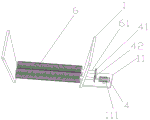
FIG. 1 is a schematic structural view of the present invention;
FIG. 2 is a schematic view of the internal structure of the stone feeding bin of the present invention;
FIG. 3 is a schematic view of the push-pull structure of the present invention;
in the figure: 1. entering a stone bin; 11. a first fixing plate; 12. screening a screen; 111. a limiting block; 2. a support plate; 21. a second rotating shaft; 22. a third rotating shaft; 3. an inclined plate; 31. a first rotating shaft; 32. a first rotating lever; 4. a first motor; 41. a first gear; 42. a second gear; 5. a storage box; 6. a crushing roller; 61. turning the column; 7. a first drive lever; 71. a limiting rod; 72. rotating the ring; 721. a push rod; 8. a second transmission rod; 81. a second fixing plate; 82. drawing the cylinder; 9. a second motor; 91. a threaded rod.
Detailed Description
The technical solutions in the embodiments of the present invention will be described clearly and completely with reference to the accompanying drawings in the embodiments of the present invention, and it is obvious that the described embodiments are only some embodiments of the present invention, not all embodiments. Based on the embodiments in the present invention, all other embodiments obtained by a person skilled in the art without creative work belong to the protection scope of the present invention.
Referring to fig. 1-3, the present invention provides a technical solution: a device for quickly crushing ores comprises a supporting plate 2, wherein a screen 12 is arranged at the end part of the supporting plate 2 and can filter and crush incompletely crushed ores again, a stone inlet bin 1 is arranged on the upper surface of the screen 12, a rotary column 61 penetrates through the side surface of the stone inlet bin 1, one end of the rotary column 61 is fixedly connected with a crushing roller 6, the ores enter from the stone inlet bin 1 and fall onto the crushing roller 6, a first gear 41 and a second gear 42 are arranged at the other end of the rotary column 61, the first gear 41 is meshed with the second gear 42, a first fixing plate 11 is arranged on the side surface of the stone inlet bin 1, a first motor 4 is arranged on the upper surface of the first fixing plate 11, the end part of the first motor 4 is fixedly connected with the second gear 42, the first motor 4 rotates to drive the second gear 42, the second gear 42 is meshed with the first gear 41 to drive the first gear 41 to rotate in the opposite direction, so that stones to be crushed by the crushing roller 6 in the stone inlet bin 1 rotate in the opposite direction are rolled and crushed, the crushed ore can fall onto the inclined plate 3 through the screen 12, the end part of the support plate 2 is provided with a first rotating shaft 31, the side surface of the first rotating shaft 31 is rotatably provided with the inclined plate 3, the inclined plate 3 can rotate around the first rotating shaft 31, the lower surface of the inclined plate 3 is rotatably provided with a first rotating rod 32, the side surface of the support plate 2 is provided with a second rotating shaft 21, the outer part of the second rotating shaft 21 is rotatably sleeved with a first transmission rod 7, the end part of the first transmission rod 7 is rotatably connected with the first rotating rod 32, the first transmission rod 7 rotates around the second rotating shaft 21 to push the first rotating rod 32, so that the inclined plate 3 is inclined, the completely crushed stone is poured into the containing box 5, the side surface of the support plate 2 is provided with a third rotating shaft 22, the outer part of the third rotating shaft 22 is rotatably sleeved with a second transmission rod 8, the side surface of the second transmission rod 8 is fixedly connected with a second fixing plate 81, the upper surface of the second fixing plate 81 is provided with a second motor 9, the end of the second motor 9 is provided with a threaded rod 91, the external thread of the threaded rod 91 is clamped with a drawing cylinder 82, the rotatable threaded rod 91 connected with the power supply of the second motor 9 pushes the push rod 721, the end of the drawing cylinder 82 is rotatably connected with the push rod 721, and the end of the push rod 721 is rotatably connected with the first transmission rod 7.
The end of the first transmission rod 7 is rotatably sleeved with a rotating ring 72, the push rod 721 is fixedly connected with the rotating ring 72, and the push rod 721 can provide a pushing force to the first transmission rod 7 by pushing the rotating ring 72.
The upper surface of the first fixing plate 11 is provided with a limiting block 111, and the upper surface of the limiting block 111 is fixedly connected with the first motor 4 to fix the first motor 4.
The end of the second transmission rod 8 is rotatably connected with a limiting rod 71, and the other end of the limiting rod 71 is rotatably connected with the first transmission rod 7, so that the first transmission rod 7 and the second transmission rod 8 can be more stably connected and can rotate synchronously.
The storage box 5 is arranged on the side face of the supporting plate 2, the inclined plate 3 inclines, and crushed stone is poured into the storage box 5 completely, so that the crushed stone can be directly collected.
The working principle is as follows: when the crushing device works, stones to be crushed can enter through the stone inlet bin 1 and are connected with the power supply of the first motor 4, the first motor 4 rotates to drive the second gear 42, the second gear 42 is meshed with the first gear 41 to drive the first gear 41 to rotate in the opposite direction, so that the crushing roller 6 in the stone inlet bin 1 rotates in the opposite direction to crush the stones to be crushed, crushed ores can fall onto the inclined plate 3 through the screen 12, stones which are not completely crushed but remain through the screen 12 to be continuously crushed, when enough stones are on the inclined plate 3, the power supply of the second motor 9 is connected to rotate the threaded rod 91 to provide a pulling force for the drawing cylinder 82, the drawing cylinder 82 is rotatably connected with the push rod 721 to draw the first transmission rod 7, the first transmission rod 7 rotates around the second rotating shaft 21 to draw the first rotating rod 32 to incline the inclined plate 3, the crushed stone is poured into the containing box 5, the first transmission rod 7 rotates to drive the second transmission rod 8 to rotate around the third rotating shaft 22, so that the pulling cylinder 82 is driven, and the first transmission rod 7 and the second transmission rod 8 are rotatably connected through the limiting rod 71 to achieve the effect of stable connection.
Although embodiments of the present invention have been shown and described, it will be appreciated by those skilled in the art that changes, modifications, substitutions and alterations can be made in these embodiments without departing from the principles and spirit of the invention, the scope of which is defined in the appended claims and their equivalents.
Claims (5)
1. The utility model provides a quick kibbling device of ore, includes backup pad (2), its characterized in that, backup pad (2) tip is equipped with screen cloth (12), screen cloth (12) upper surface is equipped with into stone storehouse (1), it runs through and is equipped with rotary column (61) to advance stone storehouse (1) side, rotary column (61) one end fixedly connected with crushing roller (6), the rotary column (61) other end is equipped with first gear (41) and second gear (42), first gear (41) and second gear (42) meshing, it is equipped with first fixed plate (11) to advance stone storehouse (1) side, first fixed plate (11) upper surface is equipped with first motor (4), first motor (4) tip and second gear (42) fixed connection, backup pad (2) tip is equipped with first pivot (31), first pivot (31) side rotates and is equipped with hang plate (3), a first rotating rod (32) is rotatably arranged on the lower surface of the inclined plate (3), a second rotating shaft (21) is arranged on the side surface of the supporting plate (2), a first transmission rod (7) is rotatably sleeved outside the second rotating shaft (21), the end part of the first transmission rod (7) is rotatably connected with a first rotating rod (32), a third rotating shaft (22) is arranged on the side surface of the supporting plate (2), a second transmission rod (8) is rotatably sleeved outside the third rotating shaft (22), a second fixing plate (81) is fixedly connected with the side surface of the second transmission rod (8), a second motor (9) is arranged on the upper surface of the second fixing plate (81), a threaded rod (91) is arranged at the end part of the second motor (9), threaded rod (91) outside screw thread card is equipped with a pull section of thick bamboo (82), pull section of thick bamboo (82) tip is rotated and is connected with push rod (721), push rod (721) tip and first transfer line (7) are rotated and are connected.
2. The device for rapidly crushing ore according to claim 1, characterized in that: the end part of the first transmission rod (7) is rotatably sleeved with a rotating ring (72), and the push rod (721) is fixedly connected with the rotating ring (72).
3. The device for rapidly crushing ore according to claim 1, characterized in that: the upper surface of the first fixing plate (11) is provided with a limiting block (111), and the upper surface of the limiting block (111) is fixedly connected with the first motor (4).
4. The device for rapidly crushing ore according to claim 1, characterized in that: the end part of the second transmission rod (8) is rotatably connected with a limiting rod (71), and the other end of the limiting rod (71) is rotatably connected with the first transmission rod (7).
5. The device for rapidly crushing ore according to claim 1, characterized in that: the side of the supporting plate (2) is provided with a containing box (5).
Priority Applications (1)
| Application Number | Priority Date | Filing Date | Title |
|---|---|---|---|
| CN202022129295.6U CN213761987U (en) | 2020-09-24 | 2020-09-24 | Quick kibbling device of ore |
Applications Claiming Priority (1)
| Application Number | Priority Date | Filing Date | Title |
|---|---|---|---|
| CN202022129295.6U CN213761987U (en) | 2020-09-24 | 2020-09-24 | Quick kibbling device of ore |
Publications (1)
| Publication Number | Publication Date |
|---|---|
| CN213761987U true CN213761987U (en) | 2021-07-23 |
Family
ID=76906310
Family Applications (1)
| Application Number | Title | Priority Date | Filing Date |
|---|---|---|---|
| CN202022129295.6U Active CN213761987U (en) | 2020-09-24 | 2020-09-24 | Quick kibbling device of ore |
Country Status (1)
| Country | Link |
|---|---|
| CN (1) | CN213761987U (en) |
Cited By (1)
| Publication number | Priority date | Publication date | Assignee | Title |
|---|---|---|---|---|
| CN116377313A (en) * | 2023-04-11 | 2023-07-04 | 江苏汇宝不锈钢有限公司 | Nickel content adding method for high nickel content stainless steel |
-
2020
- 2020-09-24 CN CN202022129295.6U patent/CN213761987U/en active Active
Cited By (2)
| Publication number | Priority date | Publication date | Assignee | Title |
|---|---|---|---|---|
| CN116377313A (en) * | 2023-04-11 | 2023-07-04 | 江苏汇宝不锈钢有限公司 | Nickel content adding method for high nickel content stainless steel |
| CN116377313B (en) * | 2023-04-11 | 2023-10-13 | 江苏汇宝不锈钢有限公司 | Nickel content adding method for high nickel content stainless steel |
Similar Documents
| Publication | Publication Date | Title |
|---|---|---|
| CN209302847U (en) | A kind of graphite grinding device with uniform crushing function | |
| CN212167711U (en) | Screening equipment for soil treatment | |
| CN207169832U (en) | A kind of water high-purity extraction element | |
| CN213761987U (en) | Quick kibbling device of ore | |
| CN214107151U (en) | Raw material crushing device for metallurgical equipment | |
| CN210675382U (en) | Lithium battery material ball-milling device | |
| CN214681959U (en) | Building waste pulverizes recovery unit | |
| CN213102591U (en) | Novel corundum crusher | |
| CN214347053U (en) | Cone crusher with dust keeper | |
| CN215197465U (en) | A pulverize equipment fast for ore | |
| CN210834248U (en) | Conveniently pulverize and be convenient for get rid of soil detection of rubble and use collection system | |
| CN215586604U (en) | Civil engineering soil reducing mechanism | |
| CN212753308U (en) | Straw returning crushing device with thickness separation function | |
| CN213254912U (en) | Practical efficient traditional chinese medicine rubbing crusher | |
| CN207013293U (en) | A kind of screening plant for stone crusher | |
| CN211216956U (en) | Caking sludge treatment is with filtering reducing mechanism | |
| CN214183368U (en) | Large vertical shaft hammering type crusher suitable for mining site | |
| CN220231069U (en) | Mineral powder sampling tube | |
| CN213611884U (en) | Efficient crushing ore crusher | |
| CN213855006U (en) | Breaker removes strutting arrangement | |
| CN217288567U (en) | Be used for metallurgical energy-concerving and environment-protective ore treatment reducing mechanism | |
| CN210585084U (en) | Reducing mechanism for industrial chemicals | |
| CN212284200U (en) | Fertilizer reducing mechanism | |
| CN213376890U (en) | Smashing device convenient for collecting materials for carbon processing | |
| CN218281937U (en) | Breaker that conductivity type macromolecular material preparation was used |
Legal Events
| Date | Code | Title | Description |
|---|---|---|---|
| GR01 | Patent grant | ||
| GR01 | Patent grant |