CN213711011U - Automatic locking mechanism of lock lever - Google Patents
Automatic locking mechanism of lock lever Download PDFInfo
- Publication number
- CN213711011U CN213711011U CN202022679435.7U CN202022679435U CN213711011U CN 213711011 U CN213711011 U CN 213711011U CN 202022679435 U CN202022679435 U CN 202022679435U CN 213711011 U CN213711011 U CN 213711011U
- Authority
- CN
- China
- Prior art keywords
- locking rod
- driving sleeve
- bearing seat
- gear
- locking
- Prior art date
- Legal status (The legal status is an assumption and is not a legal conclusion. Google has not performed a legal analysis and makes no representation as to the accuracy of the status listed.)
- Active
Links
Images


Abstract
The utility model discloses an automatic locking mechanism of a locking rod, belonging to the technical field of well drilling auxiliary equipment, comprising a bearing seat connected with one side of a blowout preventer cylinder head, a locking rod and a driving sleeve arranged in the cavity of the bearing seat, and a power mechanism for controlling the rotation of the driving sleeve; the front end of the locking rod is in threaded connection and matching with the inner wall of the bearing seat cavity, the rear end of the locking rod is movably connected with the driving sleeve, and the locking rod can rotate along with the driving sleeve and moves forwards or backwards in the bearing seat cavity relative to the driving sleeve. The utility model discloses the check lock lever is double bracing structure, and its front end adopts the threaded connection cooperation with the bearing frame inner chamber, rear end and drive cover inner hole swing joint, and the check lock lever transmission under this structure is stable, and the operation is smooth, can lock the check lock lever with the cooperation of drive cover under power unit's drive.
Description
Technical Field
The utility model belongs to the technical field of preventer locking, concretely relates to automatic locking mechanism of check lock lever.
Background
The blowout preventer is a key device for preventing blowout accidents in oil fields, and if the well is closed for a long time after the blowout happens, the locking rod of the blowout preventer must be locked in time. At present, the manual locking device is used for locking the flashboard by adopting a mechanical method after a blowout preventer is hydraulically closed, a general locking rod extends out of a derrick through a universal joint, an extension rod and a hand wheel, and when the manual locking device is used, a worker can lock the flashboard by rotating the hand wheel, so that the long-term reliable well sealing of the flashboard is ensured. Although the purpose of closing and locking the ram of the blowout preventer can be achieved, the manual locking structure has the defects that the operation is mainly completed manually, the labor intensity is high, the efficiency is low, an operator needs to record the number of turns of the rotating hand wheel, and when the ram is opened, the hand wheel needs to be reversed for the same number of turns to withdraw the locking rod so as to prevent the situation that the ram of the blowout preventer is damaged by a drilling rod due to the fact that the ram is not withdrawn in place.
In the prior art, the publication number is CN104912511A, the announcement date is 2017, 08 and 25, and the name of the Chinese invention patent is a manual-automatic integrated blowout preventer locking device, and the technical scheme is as follows: a manual-automatic integrated blowout preventer locking device comprises a blowout preventer locking system, a blowout preventer locking control system, an automatic control system and a hydraulic pipeline, wherein the blowout preventer locking system comprises an oil tank, an electric plunger pump, a pressure controller, a manual plunger pump, an energy accumulator, an electric reversing valve and a manual reversing valve, the oil tank is connected with an inlet of the electric plunger pump, an outlet of the electric plunger pump is respectively connected with the manual reversing valve, an inlet of the electric reversing valve and an inlet of the energy accumulator, an inlet of the manual plunger pump is connected with an outlet of the oil tank and an outlet of the energy accumulator, an outlet of the manual plunger pump is connected with an inlet of the manual reversing valve, and outlets of the manual reversing valve and the electric reversing valve and an inlet and an outlet of a hydraulic motor of the blowout preventer locking system are connected with.
The above patents mainly suffer from the following disadvantages: 1. one end of a locking rod in the structure is connected with a flashboard lead screw of the blowout preventer through a pin, and the other end of the locking rod is connected with a spline shaft through a pin, so that blockage is easy to occur in the rotation process of the locking rod; 2. the manual plunger pump and the manual reversing valve are arranged in the above patent for manual locking, and actually, the output flow of the manual plunger pump is extremely low, which is not enough to drive the hydraulic motor completely, so that manual unlocking cannot be realized;
disclosure of Invention
The utility model discloses aim at solving the structure that preventer locking device among the prior art exists unreasonable, the smooth easy card of preventer lock lever motion hinders the scheduling problem, provide a structure set up reasonable, the transmission is stable, the automatic locking mechanism of lock lever that the operation is smooth to be hindered.
In order to achieve the above purpose, the technical solution of the present invention is as follows:
an automatic locking mechanism of a locking rod comprises a bearing seat connected to one side of a blowout preventer cylinder head, the locking rod and a driving sleeve which are arranged in a cavity of the bearing seat, and a power mechanism for controlling the driving sleeve to rotate; the front end of the locking rod is in threaded connection and matching with the inner wall of the bearing seat cavity, the rear end of the locking rod is inserted into an inner hole of the driving sleeve and is movably connected with the inner hole, and the locking rod can rotate along with the driving sleeve and moves forwards or backwards in the bearing seat cavity relative to the driving sleeve.
The rear end of the locking rod is provided with a key strip, the inner wall of the driving sleeve is provided with a key groove matched with the shape of the key strip, and the locking rod is connected with the driving sleeve through the matching of the key strip and the key groove. The strength of the connecting structure is high.
The key strips are two and symmetrically arranged on the outer wall of the locking rod, and the outer surface of each key strip is in a quarter cylindrical surface shape. The structure can ensure the balance stress of the locking rod and avoid the blocking caused by unbalanced force.
And bearings are arranged between the inner cavity of the bearing seat and the driving sleeve and are arranged at the front end and the rear end of the driving sleeve.
The power mechanism comprises a hydraulic motor, a driving gear, a transmission gear and a power gear, the driving gear is connected to an output shaft of the hydraulic motor, and the power gear is arranged on the outer side of the driving sleeve; the transmission gear is arranged between the driving gear and the power gear and is respectively meshed with the driving gear and the power gear. The design of the transmission gear can improve the transmission ratio of the power mechanism and simultaneously expand the installation position of the hydraulic motor outwards.
The output shaft end of the hydraulic motor is connected with a manual chain wheel, and the middle of the manual chain wheel is provided with a tooth groove for clamping a chain. When the automatic locking mechanism cannot work due to power failure or faults, the manual chain wheel can facilitate an operator to manually complete locking of the locking rod.
The utility model has the advantages that:
1. in the utility model, the locking rod is a double-support structure, the front end of the locking rod is in threaded connection and matching with the inner cavity of the bearing seat, and the rear end of the locking rod is movably connected with the inner hole of the driving sleeve, so that the locking rod under the structure has stable transmission and smooth operation;
2. in the utility model, the locking rod and the driving sleeve adopt the connection mode of matching the key strip and the key groove, so that the connection strength of the structure is higher;
3. in the utility model, the key strip is designed into a symmetrical structure, which can ensure the balance stress of the locking rod and is not easy to block;
4. in the utility model, a transmission gear is arranged between the driving gear and the power gear of the hydraulic motor, and the transmission gear can improve the transmission ratio of the hydraulic motor and simultaneously expand the installation position of the hydraulic motor outwards, thereby facilitating the installation;
5. the utility model discloses in, manual sprocket is connected at hydraulic motor's output, and when the outage appeared, operating personnel can stand in the locking mechanism below, adopts chain and manual sprocket cooperation locking lever, and compares in the hand wheel transmission of straight-bar type more laborsaving.
Drawings
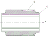
FIG. 1 is a sectional view of the structure of the present invention;
FIG. 2 is a front view of the lock lever;
FIG. 3 is a left side view of FIG. 2;
FIG. 4 is a cross-sectional view of the drive sleeve;
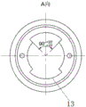
FIG. 5 is a view taken along line A of FIG. 4;
wherein the content of the first and second substances,
1. the blowout preventer cylinder head comprises a blowout preventer cylinder head body 2, a bearing seat 3, a locking rod 4, a driving sleeve 5, a bearing 6, a hydraulic motor 7, a driving gear 8, a transmission gear 9, a power gear 10, a manual chain wheel 11, a tooth groove 12, a key strip 13, a key groove 14 and threads.
Detailed Description
In order to make the objects, technical solutions and advantages of the embodiments of the present invention clearer, the embodiments of the present invention will be clearly and completely described below with reference to the accompanying drawings in the embodiments of the present invention, and it is obvious that the described embodiments are some, but not all, embodiments of the present invention. The components of embodiments of the present invention, as generally described and illustrated in the figures herein, may be arranged and designed in a wide variety of different configurations.
Thus, the following detailed description of the embodiments of the present invention, presented in the accompanying drawings, is not intended to limit the scope of the invention, as claimed, but is merely representative of selected embodiments of the invention. Based on the embodiments in the present invention, all other embodiments obtained by a person skilled in the art without creative efforts belong to the protection scope of the present invention.
It should be noted that: like reference numbers and letters refer to like items in the following figures, and thus, once an item is defined in one figure, it need not be further defined and explained in subsequent figures.
In the description of the present invention, it should be noted that the terms "upper", "vertical", "inner", "outer", and the like indicate the orientation or positional relationship based on the orientation or positional relationship shown in the drawings, or the orientation or positional relationship that the utility model is usually placed when using, or the orientation or positional relationship that a person skilled in the art usually understands, only for the convenience of describing the present invention and simplifying the description, but not for indicating or implying that the device or element that is referred to must have a specific orientation, be constructed and operated in a specific orientation, and thus, should not be construed as limiting the present invention. Furthermore, the terms "first," "second," and the like are used merely to distinguish one description from another, and are not to be construed as indicating or implying relative importance.
In the description of the present invention, it should also be noted that, unless otherwise explicitly specified or limited, the terms "disposed," "mounted," and "connected" are to be construed broadly, e.g., as meaning fixedly connected, detachably connected, or integrally connected; can be mechanically or electrically connected; they may be connected directly or indirectly through intervening media, or they may be interconnected between two elements. The specific meaning of the above terms in the present invention can be understood in specific cases to those skilled in the art.
Example 1
The embodiment discloses an automatic locking mechanism of a locking rod as shown in fig. 1, which comprises a bearing seat 2 connected to one side of a blowout preventer cylinder head 1, a locking rod 3 and a driving sleeve 4 which are arranged in a cavity of the bearing seat 2, and a power mechanism for controlling the driving sleeve 4 to rotate.
The inner cavity of the bearing seat 2 is divided into a front cavity and a rear cavity with different inner diameters, and the driving sleeve 4 is arranged at the rear end of the bearing seat 2 with a wider inner diameter through bearings 5 arranged at two ends of the driving sleeve; the front section of the locking rod 3 is positioned at the front end of the bearing seat 2 with a narrower inner diameter, the inner wall of the front end of the bearing seat 2 is provided with an internal thread 14, the front section of the locking rod 3 is provided with an external thread 14, and the locking rod and the external thread 14 are connected and matched through the thread 14; the rear section of the locking rod 3 is inserted into an inner hole of the driving sleeve 4 to be matched with the inner hole, the tail end of the locking rod 3 is provided with a key strip 12, the inner wall of the driving sleeve 4 is provided with a key groove 13 matched with the shape of the key strip 12, and the key strip 12 is matched with the key groove 13 to enable the locking rod 3 to be movably connected with the driving sleeve 4.
As shown in fig. 1, the power mechanism comprises a hydraulic motor 6, a driving gear 7, a transmission gear 8 and a power gear 9, the driving gear 7 is connected to an output shaft of the hydraulic motor 6, and the power gear 9 is fixedly arranged at the outer side of the driving sleeve 4; the transmission gear 8 is arranged between the driving gear 7 and the power gear 9 and is respectively meshed with the driving gear 7 and the power gear 9. The transmission gear 8 can improve the transmission ratio of the hydraulic motor 6, and simultaneously, the installation position of the hydraulic motor 6 is extended outwards, so that the installation is convenient.
The hydraulic motor 6 is connected with a hydraulic control system, the hydraulic control system comprises an oil tank, an electric plunger pump, an electromagnetic overflow valve, an electromagnetic directional valve and a connecting pipeline, the oil tank is connected with an inlet of the electric plunger pump, an outlet of the electric plunger pump is connected with the electromagnetic directional valve, and an outlet and a return port of the electromagnetic directional valve are connected with an inlet and an outlet of the electric plunger pump.
The working principle of the mechanism is as follows:
when the hydraulic control system works, the hydraulic control system is started, the hydraulic motor 6 is started to drive the driving gear 7 to rotate, the driving gear 7 drives the transmission gear 8 to rotate, the transmission gear 8 drives the power gear 9 to rotate, so that the driving sleeve 4 is driven to keep rotating in situ in a cavity at the rear end of the bearing seat 2, the locking rod 3 and the driving sleeve 4 are also kept rotating synchronously, and meanwhile, under the action of the front section threads 14 of the locking rod 3, the locking rod 3 is pushed forward relative to the driving sleeve 4 while rotating until the locking rod is locked; the hydraulic control system controls the hydraulic motor 6 to rotate reversely, and the locking rod 3 moves backwards to release the locking rod.
Example 2
On the basis of embodiment 1, further referring to fig. 1 in the specification, an output shaft end of the hydraulic motor 6 is connected with a manual sprocket 10, and a tooth groove 11 for clamping a chain is formed in the middle of the manual sprocket 10. When power failure or failure occur to enable the automatic locking mechanism to work, the manual chain wheel can facilitate the manual locking of the locking rod of an operator, during use, the operator can stand below the locking mechanism and rotate the manual chain wheel through the chain, so that the manual locking effect is achieved, and the manual locking device is more time-saving and labor-saving compared with general straight-bar type manual wheel locking.
Example 3
The embodiment discloses an automatic locking mechanism of a locking rod, and further, on the basis of embodiment 1, as shown in fig. 2-3, in order to ensure balanced stress of the locking rod 3, two key strips 12 are symmetrically arranged on the outer wall of the locking rod 3, and the outer surface of each key strip 12 is in the shape of a smooth quarter cylindrical surface.
The above is only the preferred embodiment of the present invention, not to the limitation of the present invention in any form, all the technical matters of the present invention all fall into the protection scope of the present invention to any simple modification and equivalent change of the above embodiments.
Claims (6)
1. The utility model provides an automatic locking mechanism of check lock pole which characterized in that: the blowout preventer comprises a bearing seat (2) connected to one side of a blowout preventer cylinder head (1), a locking rod (3) and a driving sleeve (4) which are arranged in a cavity of the bearing seat (2), and a power mechanism for controlling the driving sleeve (4) to rotate; the front end of the locking rod (3) is connected and matched with the inner wall of the cavity of the bearing seat (2) through threads (14), the rear end of the locking rod (3) is inserted into an inner hole of the driving sleeve (4) to be movably connected with the inner hole, and the locking rod (3) can rotate together with the driving sleeve (4) and moves forward or backward in the cavity of the bearing seat (2) relative to the driving sleeve (4).
2. The automatic lock mechanism of claim 1, wherein: the rear end of the locking rod (3) is provided with a key strip (12), the inner wall of the driving sleeve (4) is provided with a key groove (13) matched with the key strip (12) in shape, and the locking rod (3) is connected with the driving sleeve (4) through the matching of the key strip (12) and the key groove (13).
3. The automatic lock mechanism of claim 2, wherein: the two key strips (12) are symmetrically arranged on the outer wall of the locking rod (3), and the outer surface of each key strip (12) is in a quarter cylindrical surface shape.
4. The automatic lock mechanism of claim 1, wherein: and a bearing (5) is arranged between the inner cavity of the bearing seat (2) and the driving sleeve (4), and the bearing (5) is arranged at the front end and the rear end of the driving sleeve (4).
5. The automatic lock mechanism of claim 1, wherein: the power mechanism comprises a hydraulic motor (6), a driving gear (7), a transmission gear (8) and a power gear (9), the driving gear (7) is connected to an output shaft of the hydraulic motor (6), and the power gear (9) is arranged on the outer side of the driving sleeve (4); the transmission gear (8) is arranged between the driving gear (7) and the power gear (9) and is respectively meshed with the driving gear (7) and the power gear (9).
6. The automatic lock mechanism of claim 5, wherein: the output shaft end of the hydraulic motor (6) is connected with a manual chain wheel (10), and the middle of the manual chain wheel (10) is provided with a tooth groove (11) for clamping a chain.
Priority Applications (1)
| Application Number | Priority Date | Filing Date | Title |
|---|---|---|---|
| CN202022679435.7U CN213711011U (en) | 2020-11-19 | 2020-11-19 | Automatic locking mechanism of lock lever |
Applications Claiming Priority (1)
| Application Number | Priority Date | Filing Date | Title |
|---|---|---|---|
| CN202022679435.7U CN213711011U (en) | 2020-11-19 | 2020-11-19 | Automatic locking mechanism of lock lever |
Publications (1)
| Publication Number | Publication Date |
|---|---|
| CN213711011U true CN213711011U (en) | 2021-07-16 |
Family
ID=76806416
Family Applications (1)
| Application Number | Title | Priority Date | Filing Date |
|---|---|---|---|
| CN202022679435.7U Active CN213711011U (en) | 2020-11-19 | 2020-11-19 | Automatic locking mechanism of lock lever |
Country Status (1)
| Country | Link |
|---|---|
| CN (1) | CN213711011U (en) |
-
2020
- 2020-11-19 CN CN202022679435.7U patent/CN213711011U/en active Active
Similar Documents
| Publication | Publication Date | Title |
|---|---|---|
| DE2552095C2 (en) | Apparatus and method for letting in and pulling up pipes in boreholes or out of boreholes | |
| DE60005198T2 (en) | DEVICE AND METHOD FOR SIMPLY CONNECTING TUBES | |
| WO2017084226A1 (en) | Cable-type electrohydraulic control pipe cutting tool | |
| CN101832114B (en) | High-efficiency hydraulic twisting machine capable of staggering orifice | |
| CN105951703B (en) | A kind of hydraulic system of gear-rack type lifter structure | |
| CN108119083B (en) | Hydraulic drive well head oil pipe cutting knife | |
| CN213711011U (en) | Automatic locking mechanism of lock lever | |
| CN109577895B (en) | Gear and rack transmission type rotary locking mechanism | |
| DE3707249A1 (en) | PUSH-REDUCER METHOD AND DEVICE FOR A HOLE PUMP, IN PARTICULAR A SPINDLE PUMP | |
| CN201650161U (en) | Hydraulic system of hydraulic twisting machine | |
| CN211259236U (en) | Hydraulic wind wheel lock of wind generating set | |
| CN203626800U (en) | Automatic alignment controller of hydraulic power tongs | |
| CN112253031A (en) | Hydraulic rotary booster tool | |
| CN110029962B (en) | Remote quick-connection device for check valve and oil pipe plug valve of drilling tool for drilling and repairing well | |
| CN202989938U (en) | Pipe extractor for well point pipe | |
| CN209687433U (en) | Scissors V shape tubing string clamp | |
| CN110017113A (en) | Hand integrated hydraulic fast opened preventer | |
| CN213711012U (en) | Automatic locking device of lock lever | |
| CN214465272U (en) | Plunger cylinder test hydraulic system | |
| CN210637520U (en) | Novel butterfly valve | |
| CN212202375U (en) | Bidirectional high-pressure large-flow grouting pump | |
| CN210659988U (en) | Drill rod clamping device for underground rope coring | |
| CN103382928A (en) | Hydraulic manual pump | |
| CN114517656A (en) | Automatic locking control method for locking rod | |
| CN107165601B (en) | Drill rod dead clamp and control method thereof |
Legal Events
| Date | Code | Title | Description |
|---|---|---|---|
| GR01 | Patent grant | ||
| GR01 | Patent grant |