CN213702590U - Clamping and positioning device for processing roller of microwave oven - Google Patents
Clamping and positioning device for processing roller of microwave oven Download PDFInfo
- Publication number
- CN213702590U CN213702590U CN202022922432.1U CN202022922432U CN213702590U CN 213702590 U CN213702590 U CN 213702590U CN 202022922432 U CN202022922432 U CN 202022922432U CN 213702590 U CN213702590 U CN 213702590U
- Authority
- CN
- China
- Prior art keywords
- clamping
- microwave oven
- threaded rod
- gyro wheel
- positioning device
- Prior art date
- Legal status (The legal status is an assumption and is not a legal conclusion. Google has not performed a legal analysis and makes no representation as to the accuracy of the status listed.)
- Active
Links
Images

Landscapes
- Constitution Of High-Frequency Heating (AREA)
Abstract
The utility model belongs to the technical field of microwave oven gyro wheel processing, especially, be a clamping positioner is used in microwave oven gyro wheel processing, to microwave oven gyro wheel clamping positioner among the prior art to the clamping location complex operation of gyro wheel, reduced the machining efficiency to the gyro wheel, awkward problem, the following scheme is proposed at present, and it includes the workstation, the equal fixed mounting in bottom four corners of workstation has the landing leg, and the front side of workstation is seted up the spread groove, rotates the top of installing the threaded rod on the top inner wall of spread groove, and the bottom of threaded rod extends to the below and the fixed mounting of workstation has the knob, and the movable plate is installed to the outside screw thread of threaded rod, and the equal fixed mounting in top both sides of movable plate has three hornblocks, has seted up two openings on the top inner wall of spread groove. The utility model has the advantages of reasonable design, easy operation is convenient for carry out the clamping location to the microwave oven gyro wheel, and convenient to use has improved the machining efficiency to the microwave oven gyro wheel.
Description
Technical Field
The utility model relates to a microwave oven gyro wheel processing technology field especially relates to a clamping positioner is used in microwave oven gyro wheel processing.
Background
A microwave oven refers to a household or industrial appliance that heats an object (mainly polar molecules such as water) using electromagnetic waves of a microwave band. The microwave oven is composed of power supply, magnetron, control circuit and cooking cavity. Near the entrance of the cavity, there is a rotatable stirrer, which is a fan-shaped metal, and which has all directional reflections of the microwave after rotating, so that the microwave energy can be uniformly distributed in the cavity, thereby heating the food. The power range is typically 500-1000W, which is one of the essential parts for the roller of microwave oven.
However, in the process of machining the microwave oven roller, the microwave oven roller is usually required to be clamped and positioned and then machined, however, the clamping and positioning operation of the microwave oven roller clamping and positioning device to the roller in the prior art is complicated, the machining efficiency of the roller is reduced, and the use is inconvenient, so that the clamping and positioning device for machining the microwave oven roller is provided for solving the problems.
SUMMERY OF THE UTILITY MODEL
The utility model aims at solving the clamping positioning operation of microwave oven gyro wheel clamping positioner to the gyro wheel among the prior art loaded down with trivial details, reduced the machining efficiency to the gyro wheel, awkward shortcoming, and a clamping positioner is used in microwave oven gyro wheel processing that proposes.
In order to achieve the above purpose, the utility model adopts the following technical scheme:
a clamping and positioning device for microwave oven roller processing comprises a workbench, wherein supporting legs are fixedly arranged at four corners of the bottom of the workbench, a connecting groove is formed in the front side of the workbench, the top end of a threaded rod is rotatably arranged on the inner wall of the top of the connecting groove, the bottom end of the threaded rod extends to the lower side of the workbench and is fixedly provided with a knob, a movable plate is threadedly arranged at the outer side of the threaded rod, three triangular blocks are fixedly arranged at two sides of the top of the movable plate, two openings are formed in the inner wall of the top of the connecting groove, connecting plates are slidably arranged in the two openings, the bottoms of the two connecting plates extend into the connecting groove and are rotatably provided with rollers, the two rollers are respectively in rolling contact with bevel edges of the corresponding three triangular blocks, baffles are fixedly arranged at two sides of the top of the workbench, one side, close to each other, of a plurality of springs is fixedly provided with one end, the, the clamping rings are fixedly mounted on the side, close to each other, of the two connecting plates, and a plurality of protrusions are arranged on the side, close to each other, of the two clamping rings.
Preferably, the bottom inner wall of the connecting groove is provided with a mounting hole, an outer ring of the bearing is fixedly mounted in the mounting hole, and the threaded rod is fixedly sleeved with an inner ring of the bearing and convenient to rotate and mount.
Preferably, the top of the moving plate is provided with a threaded hole, and the moving plate is installed on the outer side of the threaded rod through the threaded hole, so that the moving plate is conveniently in threaded connection with the threaded rod.
Preferably, two vertical rods are fixedly mounted in the connecting groove, and the moving plate is connected to the outer sides of the two vertical rods in a sliding mode and plays a certain limiting role in the moving plate.
Preferably, two limiting rods are fixedly mounted in the opening, and the connecting plate is connected to the outer sides of the two limiting rods in a sliding mode and plays a certain limiting role in the connecting plate.
Preferably, the bottom of connecting plate fixed mounting has the cardboard, the front side fixedly connected with clamping bar's of cardboard one end, and the other end and the gyro wheel of clamping bar rotate to be connected, are convenient for rotate the installation gyro wheel.
In the utility model, the clamping and positioning device for microwave oven roller processing drives the threaded rod to rotate by rotating the knob, so that the movable plate can be driven to move upwards by the threaded connection of the movable plate and the threaded rod, and further the movable plate can drive the two triangular blocks to move upwards, and then the two connecting plates can be driven to move close to each other by the two rollers and a plurality of springs can be stretched in the process of moving the two triangular blocks upwards by the rolling contact of the roller and the triangular blocks, so that the two clamping rings can move close to each other to clamp and position the microwave oven roller, the operation is simple, the use is convenient, and the processing efficiency of the microwave oven roller is improved;
the utility model has the advantages of reasonable design, easy operation is convenient for carry out the clamping location to the microwave oven gyro wheel, and convenient to use has improved the machining efficiency to the microwave oven gyro wheel.
Drawings
FIG. 1 is a schematic structural view of a clamping and positioning device for processing a roller of a microwave oven according to the present invention;
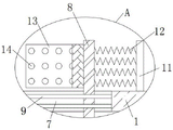
FIG. 2 is a schematic structural view of part A of the clamping and positioning device for processing the roller of the microwave oven according to the present invention;
fig. 3 is a schematic view of a top view of the clamping ring of the clamping and positioning device for microwave oven roller processing according to the present invention.
In the figure: 1. a work table; 2. a support leg; 3. connecting grooves; 4. a threaded rod; 5. moving the plate; 6. a triangular block; 7. an opening; 8. a connecting plate; 9. a limiting rod; 10. a roller; 11. a baffle plate; 12. a spring; 13. a clamping ring; 14. and (4) protruding.
Detailed Description
The technical solutions in the embodiments of the present invention will be described clearly and completely with reference to the accompanying drawings in the embodiments of the present invention, and it is obvious that the described embodiments are only some embodiments of the present invention, not all embodiments.
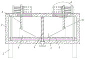
Referring to fig. 1-3, a clamping and positioning device for microwave oven roller processing comprises a workbench 1, wherein four corners of the bottom of the workbench 1 are fixedly provided with supporting legs 2, the front side of the workbench 1 is provided with a connecting groove 3, the inner wall of the top of the connecting groove 3 is rotatably provided with the top end of a threaded rod 4, the bottom end of the threaded rod 4 extends to the lower part of the workbench 1 and is fixedly provided with a knob, the outer side of the threaded rod 4 is provided with a movable plate 5 in a threaded manner, two sides of the top of the movable plate 5 are fixedly provided with triangular blocks 6, the inner wall of the top of the connecting groove 3 is provided with two openings 7, the two openings 7 are respectively and slidably provided with connecting plates 8, the bottoms of the two connecting plates 8 extend to the connecting groove 3 and are rotatably provided with rollers 10, the two rollers 10 are respectively in rolling contact with the bevel edges of, the equal fixed mounting in one side that two baffles 11 are close to each other has the one end of a plurality of springs 12, the other end that lies in a plurality of springs 12 of homonymy in a plurality of springs 12 respectively with corresponding connecting plate 8 fixed connection, the equal fixed mounting in one side that two connecting plates 8 are close to each other has clamp ring 13, one side that two clamp rings 13 are close to each other all is equipped with a plurality of archs 14.
The inner wall of the bottom of the connecting groove 3 is provided with a mounting hole, the inner ring of the bearing is fixedly arranged in the mounting hole, the threaded rod 4 is fixedly sleeved with the inner ring of the bearing, the threaded rod 4 is convenient to rotate and mount, the top of the movable plate 5 is provided with a threaded hole, the movable plate 5 is arranged on the outer side of the threaded rod 4 through the threaded hole, the movable plate 5 is convenient to be in threaded connection with the threaded rod 4, the two vertical rods are fixedly arranged in the connecting groove 3, the movable plate 5 is connected on, plays a certain limiting role on the moving plate 5, two limiting rods 9 are fixedly arranged in the opening 7, the connecting plate 8 is connected with the outer sides of the two limiting rods 9 in a sliding way, play certain limiting displacement to connecting plate 8, the bottom fixed mounting of connecting plate 8 has the cardboard, the front side fixedly connected with card pole's of cardboard one end, and the other end and the gyro wheel 10 of card pole rotate to be connected, are convenient for rotate installation gyro wheel 10.
The utility model discloses in, when using, at first place the microwave oven gyro wheel at the top of workstation 1, then the rotating knob drives threaded rod 4 and rotates, thereby can be through the threaded connection of movable plate 5 with threaded rod 4, can drive movable plate 5 and upwards remove, and then can make movable plate 5 drive two three hornblocks 6 rebound, at the same time, through the rolling contact of gyro wheel 10 with three hornblocks 6, can be at the in-process of two three hornblocks 6 rebound, drive two connecting plates 8 through two gyro wheels 10 and be close to each other and remove, and tensile a plurality of springs 12, thereby can make two clamp rings 13 be close to each other and remove and press from both sides tight location with the microwave oven gyro wheel, and the operation is simple, high durability and convenient use, and high processing efficiency to the microwave oven gyro wheel.
Claims (6)
1. The clamping and positioning device for processing the roller of the microwave oven comprises a workbench (1) and is characterized in that supporting legs (2) are fixedly mounted at four corners of the bottom of the workbench (1), a connecting groove (3) is formed in the front side of the workbench (1), the top end of a threaded rod (4) is rotatably mounted on the inner wall of the top of the connecting groove (3), the bottom end of the threaded rod (4) extends to the lower portion of the workbench (1) and is fixedly provided with a knob, a movable plate (5) is mounted on the outer side of the threaded rod (4) in a threaded manner, triangular blocks (6) are fixedly mounted on two sides of the top of the movable plate (5), two openings (7) are formed in the inner wall of the top of the connecting groove (3), connecting plates (8) are slidably mounted in the two openings (7), the bottoms of the two connecting plates (8) extend into the connecting groove (3), two gyro wheels (10) respectively with the hypotenuse rolling contact of corresponding triangle piece (6), the equal fixed mounting in top both sides of workstation (1) has baffle (11), the equal fixed mounting in one side that two baffle (11) are close to each other has the one end of a plurality of springs (12), the other end that lies in a plurality of springs (12) of homonymy in a plurality of springs (12) respectively with corresponding connecting plate (8) fixed connection, the equal fixed mounting in one side that two connecting plate (8) are close to each other has clamp ring (13), one side that two clamp ring (13) are close to each other all is equipped with a plurality of archs (14).
2. The clamping and positioning device for microwave oven roller processing as claimed in claim 1, wherein the inner wall of the bottom of the connecting groove (3) is provided with a mounting hole, the outer ring of the bearing is fixedly mounted in the mounting hole, and the threaded rod (4) is fixedly sleeved with the inner ring of the bearing.
3. The clamping and positioning device for microwave oven roller processing as claimed in claim 1, wherein the top of the moving plate (5) is provided with a threaded hole, and the moving plate (5) is installed on the outer side of the threaded rod (4) through the threaded hole.
4. The clamping and positioning device for microwave oven roller processing as claimed in claim 1, wherein two vertical rods are fixedly installed in the connecting groove (3), and the moving plate (5) is slidably connected to the outer sides of the two vertical rods.
5. The clamping and positioning device for microwave oven roller processing according to claim 1, wherein two limiting rods (9) are fixedly installed in the opening (7), and the connecting plate (8) is slidably connected to the outer sides of the two limiting rods (9).
6. The clamping and positioning device for microwave oven roller processing as claimed in claim 1, wherein the bottom of the connecting plate (8) is fixedly provided with a clamping plate, the front side of the clamping plate is fixedly connected with one end of a clamping rod, and the other end of the clamping rod is rotatably connected with the roller (10).
Priority Applications (1)
| Application Number | Priority Date | Filing Date | Title |
|---|---|---|---|
| CN202022922432.1U CN213702590U (en) | 2020-12-09 | 2020-12-09 | Clamping and positioning device for processing roller of microwave oven |
Applications Claiming Priority (1)
| Application Number | Priority Date | Filing Date | Title |
|---|---|---|---|
| CN202022922432.1U CN213702590U (en) | 2020-12-09 | 2020-12-09 | Clamping and positioning device for processing roller of microwave oven |
Publications (1)
| Publication Number | Publication Date |
|---|---|
| CN213702590U true CN213702590U (en) | 2021-07-16 |
Family
ID=76786776
Family Applications (1)
| Application Number | Title | Priority Date | Filing Date |
|---|---|---|---|
| CN202022922432.1U Active CN213702590U (en) | 2020-12-09 | 2020-12-09 | Clamping and positioning device for processing roller of microwave oven |
Country Status (1)
| Country | Link |
|---|---|
| CN (1) | CN213702590U (en) |
Cited By (1)
| Publication number | Priority date | Publication date | Assignee | Title |
|---|---|---|---|---|
| CN115647435A (en) * | 2022-11-10 | 2023-01-31 | 甘肃光轩高端装备产业有限公司 | Drilling tool |
-
2020
- 2020-12-09 CN CN202022922432.1U patent/CN213702590U/en active Active
Cited By (1)
| Publication number | Priority date | Publication date | Assignee | Title |
|---|---|---|---|---|
| CN115647435A (en) * | 2022-11-10 | 2023-01-31 | 甘肃光轩高端装备产业有限公司 | Drilling tool |
Similar Documents
| Publication | Publication Date | Title |
|---|---|---|
| CN211332908U (en) | Supporting appliance for flange | |
| CN213702590U (en) | Clamping and positioning device for processing roller of microwave oven | |
| CN211859894U (en) | Novel assembly structure of compressor motor | |
| CN109014847B (en) | Cubical switchboard rapid Assembly frock | |
| CN208591983U (en) | A kind of hard circuit board production spray tin hanger | |
| CN216228578U (en) | Cylinder shell grinding device for machining sub-cylinder | |
| CN208499745U (en) | A kind of steel plate processing equipment hand | |
| CN209801573U (en) | Oil smoke purifies all-in-one fixed mounting device | |
| CN208906930U (en) | A kind of steel plate processing equipment hand | |
| CN206556437U (en) | A kind of industrial furnace feed device | |
| CN214142470U (en) | Mechanical metal material surface hardness heat treatment equipment | |
| CN208788215U (en) | A kind of motor processing grinding device convenient for polishing | |
| CN209095218U (en) | Grinding device is used in a kind of processing of Tractor Components | |
| CN110666545B (en) | Axial cutting device of nonrust steel pipe | |
| CN211491220U (en) | Metal base casting base station | |
| CN211488230U (en) | Air-dry device after switch board panel surface anticorrosive spraying | |
| CN210336887U (en) | Kitchen board tectorial membrane device is used in gas-cooker production | |
| CN220649890U (en) | Belt pulley dynamic balance detection device | |
| CN220926857U (en) | Tempering equipment for heat treatment and processing of hardware | |
| CN220680247U (en) | Fixing device that automobile wheel hub processing was used | |
| CN218746284U (en) | Punching clamp for machining slide rail | |
| CN210388373U (en) | Alloy ex-trusions production is with removing cutting machine | |
| CN209520747U (en) | A kind of timber burnishing device easy to remove for building | |
| CN212128236U (en) | Full-automatic high-frequency heat treatment equipment | |
| CN220074124U (en) | Flange polishing equipment |
Legal Events
| Date | Code | Title | Description |
|---|---|---|---|
| GR01 | Patent grant | ||
| GR01 | Patent grant |