CN213678967U - Cement manufacture line kiln head clinker conveying device with multiple feeding channels - Google Patents
Cement manufacture line kiln head clinker conveying device with multiple feeding channels Download PDFInfo
- Publication number
- CN213678967U CN213678967U CN202021810715.0U CN202021810715U CN213678967U CN 213678967 U CN213678967 U CN 213678967U CN 202021810715 U CN202021810715 U CN 202021810715U CN 213678967 U CN213678967 U CN 213678967U
- Authority
- CN
- China
- Prior art keywords
- discharging
- discharge
- clinker
- kiln head
- communicated
- Prior art date
- Legal status (The legal status is an assumption and is not a legal conclusion. Google has not performed a legal analysis and makes no representation as to the accuracy of the status listed.)
- Active
Links
Images


Abstract
The utility model relates to the technical field of clinker transportation in cement plants, and provides a clinker conveying device with multiple feeding channels for a cement production line kiln head, which comprises a diagonal chain pulling machine, wherein the diagonal chain pulling machine conveys clinker cooled by kiln head equipment to a clinker warehouse; the kiln head equipment is characterized by further comprising a second feeding channel, wherein the second feeding channel comprises a discharging chamber and a discharging pipe which are arranged on one side of the kiln head equipment, and the discharging chamber comprises a discharging lane, and a gate and a discharging opening which are arranged at two ends of the discharging lane; the discharge opening is communicated to the upper part of the cable-stayed chain machine through a discharge pipe. The unloading car enters the unloading chamber along the lane, and cement clinker can be poured onto the cable-stayed chain machine only by tipping the bucket above the unloading opening, so that the unloading process is convenient and rapid, and the safety in the unloading process is also improved.
Description
Technical Field
The utility model relates to a technical field of cement plant grog transportation, concretely relates to cement manufacture line kiln head grog conveyor of many pan feeding passageways.
Background
The cement clinker produced in a clinker production workshop of a cement plant is cooled by kiln head equipment and then enters a cable-stayed chain machine along a channel below the kiln head equipment, and the cable-stayed chain machine conveys the cement clinker to a clinker warehouse; however, due to environmental protection problems, limestone for producing cement clinker is often purchased only in limited quantities, a rotary kiln for producing cement clinker cannot continuously and normally produce for a long time, clinker is purchased to meet the requirement of cement production, a discharging vehicle needs to enter a warehouse to dump and unload, and the condition is complex and has great potential safety hazard due to poor light in the warehouse and a plurality of discharging points on the ground.
In order to change the current situation that the discharging in the warehouse is unsafe and meet the requirement of environmental protection, and simultaneously, in order to ensure the stable supply of clinker, a feeding channel for discharging the purchased clinker by a discharging vehicle needs to be additionally arranged on the original clinker conveying device.
SUMMERY OF THE UTILITY MODEL
Therefore, the utility model provides a cement manufacture line kiln hood clinker conveyor of many pan feeding passageways can overcome the dummy car of delivery cement clinker among the prior art difficulty of unloading, unsafe defect.
In order to solve the above technical problems, the following technical solutions are proposed:
the utility model provides a cement production line kiln head clinker conveying device with multiple feeding channels, which comprises a diagonal chain pulling machine, wherein the diagonal chain pulling machine conveys clinker cooled by kiln head equipment to a clinker warehouse; the kiln head equipment is characterized by further comprising a second feeding channel, wherein the second feeding channel comprises a discharging chamber and a discharging pipe which are arranged on one side of the kiln head equipment, and the discharging chamber comprises a discharging lane, and a gate and a discharging opening which are arranged at two ends of the discharging lane; the discharge opening is communicated to the upper part of the cable-stayed chain machine through a discharge pipe.
The discharge pipe comprises a discharge hopper, a discharge cover and a discharge baffle edge, the top surface of the discharge hopper is communicated with the discharge opening, and the bottom surface of the discharge hopper is communicated with the discharge cover through a discharge valve; the discharging flanges are arranged on two sides of the discharging cover, protective nets are arranged on two sides of the cable-stayed chain machine, and the discharging flanges are abutted to the upper ends or the outer sides of the protective nets.
A top cover in the shape of an inverted funnel is arranged above the discharge opening, a vertically placed U-shaped baffle is arranged outside the discharge opening, and the U-shaped opening of the baffle faces a discharge lane; and a dustproof separation blade is arranged between the top cover and the baffle, one end of the dustproof separation blade is fixedly connected to the top cover, and the other end of the dustproof separation blade is fixedly connected to the baffle.
And a filter screen is arranged in the discharge port.
And a vibration device is arranged on one side of the filter screen.
And a dust collector is also arranged on one side of the unloading chamber, and the dust collector is communicated with the unloading chamber through at least one dust collecting pipe.
The dust collector is communicated with the discharge chamber through a first dust collecting pipe and a second dust collecting pipe; the first dust collecting pipe is communicated with the top cover, and the second dust collecting pipe is communicated with the upper side of the outer wall of the unloading chamber.
The dust collector is also provided with a dust exhaust pipe and a third dust collection pipe, and the dust exhaust pipe and the third dust collection pipe are communicated to the discharging cover.
The utility model has the advantages of it is following:
1. cement clinker produced by a cement plant can enter the inclined chain pulling machine after being cooled by kiln head equipment, in addition, a second feeding channel is additionally arranged on the device, the second feeding channel comprises a discharging chamber and a discharging pipe, a lane for a discharging vehicle to enter and exit is arranged in the discharging chamber, a gate and a discharging opening are arranged at two ends of the lane, the discharging vehicle enters the discharging chamber along the lane, the cement clinker can be poured into the discharging opening only by tipping over the discharging opening, the discharging process is convenient and rapid, and the safety in the discharging process is also improved; the discharge opening communicates to the top of cable-stay chain machine through the discharge tube, and the cement clinker who pours into from the discharge opening can be along the discharge tube gets into on the cable-stay chain machine.
2. The discharge pipe comprises a discharge hopper, a discharge cover and a discharge baffle edge, the discharge hopper is communicated with the discharge cover through a discharge valve, the speed of cement clinker poured from the discharge opening into the cable-stayed chain machine can be controlled by adjusting the discharge valve, and the cement clinker on the cable-stayed chain machine is not excessive; the discharging flanges are arranged on two sides above the cable-stayed chain machine and communicated with a discharging valve, and the discharging flanges can effectively prevent dust diffusion in the discharging process.
3. Be equipped with the top cap of the shape of falling funnel above the discharge opening, still be equipped with three baffles of end to end around the discharge opening, moreover the top cap with still be provided with dustproof separation blade between the baffle, top cap, baffle, dustproof separation blade constitute semi-enclosed shape together, can prevent effectively that the dust that produces at the in-process of unloading spreads to whole unloading indoorly to improve the indoor air quality of unloading.
4. Install the filter screen in the discharge opening, pour cement clinker into at the dummy car in the discharge opening, the filter screen can effectively filter out the foreign matter that dopes in the cement clinker, improves cement clinker's quality.
5. The vibrating device is arranged on one side of the filter screen, a large amount of cement clinker enters the discharge opening at the same time in the discharging process, so that the blockage phenomenon is easy to occur, the vibrating device is additionally arranged on one side of the filter screen and can vibrate the cement clinker, the accumulated cement clinker is made to fall, and the blockage problem is solved.
6. A dust collector is also arranged on one side of the discharging chamber and is communicated with the discharging chamber through a first dust collecting pipe and a second dust collecting pipe; the first dust collecting pipe is communicated with the top cover, most of dust generated in the discharging process can be accumulated in an area between the top cover and the discharging opening, and the first dust collecting pipe can collect the dust in the area into the dust collector; the second dust collecting pipe is directly communicated with the outer wall of the discharging chamber, dust diffused to the discharging chamber can be collected in the dust collector, and the purifying effect of the dust collector is improved.
Drawings
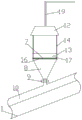
FIG. 1 is a structural diagram of a kiln head clinker conveying device of a cement production line with multiple feeding channels;
FIG. 2 is a schematic view of the connection of the discharge chamber and the dust collector.
FIG. 3 is a front view of the discharge chamber;
FIG. 4 is a right side sectional view of the discharge chamber;
FIG. 5 is a front view of the discharge opening;
fig. 6 is a left side sectional view of the discharge port.
Description of reference numerals:
1-diagonal chain drawing machine, 2-kiln head equipment, 3-discharge chamber, 4-discharge pipe, 5-discharge lane, 6-gate, 7-discharge opening, 8-discharge hopper, 9-discharge valve, 10-discharge cover, 11-discharge baffle edge, 12-top cover, 13-baffle, 14-dustproof baffle, 15-protective screen, 16-filter screen, 17-vibrating device, 18-dust collector, 19-first dust collecting pipe, 20-second dust collecting pipe, 21-third dust collecting pipe and 22-dust discharging pipe.
Detailed Description
The technical solution of the present invention will be described clearly and completely with reference to the accompanying drawings, and obviously, the described embodiments are some, but not all embodiments of the present invention. Based on the embodiments in the present invention, all other embodiments obtained by a person skilled in the art without creative work belong to the protection scope of the present invention.
In the description of the present invention, it should be noted that the terms "center", "upper", "lower", "left", "right", "vertical", "horizontal", "inner", "outer", and the like indicate orientations or positional relationships based on the orientations or positional relationships shown in the drawings, and are only for convenience of description and simplification of description, but do not indicate or imply that the device or element referred to must have a specific orientation, be constructed and operated in a specific orientation, and thus, should not be construed as limiting the present invention. Furthermore, the terms "first," "second," and "third" are used for descriptive purposes only and are not to be construed as indicating or implying relative importance.
In the description of the present invention, it is to be noted that, unless otherwise explicitly specified or limited, the terms "mounted," "connected," and "connected" are to be construed broadly, and may be, for example, fixedly connected, detachably connected, or integrally connected; can be mechanically or electrically connected; they may be connected directly or indirectly through intervening media, or they may be interconnected between two elements. The specific meaning of the above terms in the present invention can be understood in specific cases to those skilled in the art.
Furthermore, the technical features mentioned in the different embodiments of the invention described below can be combined with each other as long as they do not conflict with each other.
The cement production line kiln head clinker conveying device with multiple feeding channels as shown in fig. 1 comprises a cable-stayed chain machine 1, wherein the cable-stayed chain machine 1 conveys clinker cooled by kiln head equipment 2 to a clinker warehouse; the device is also provided with a second feeding channel, the second feeding channel comprises a discharging chamber 3 and a discharging pipe 4 which are arranged on one side of the kiln head equipment 2, and the discharging chamber 3 comprises a discharging lane 5, and a gate 6 and a discharging opening 7 which are arranged at two ends of the discharging lane 5; the discharge opening 7 is communicated to the upper part of the cable-stayed chain machine 1 through a discharge pipe 4.
The clinker conveying device is provided with two feeding channels; clinker produced by a cement plant enters the cable-stayed chain machine 1 after being cooled by the kiln head equipment 2, purchased clinker is carried to the discharge opening 7 of the second feeding channel by the discharge car and is discharged, and the discharged clinker enters the cable-stayed chain machine 1 along the discharge pipe 4. Due to poor light in a clinker production workshop and a plurality of discharging points on the ground, the situation is complex, the unloading is not beneficial to tipping the unloading car by the unloading car, and by additionally arranging the second feeding channel, the unloading car for carrying the clinker does not need to enter the clinker production workshop to unload and only needs to unload the clinker to the discharging opening 7, so that the unloading process efficiency is improved, and the possibility of safety accidents is reduced.
Specifically, the diagonal chain drawing machine 1 is provided with a conveyor belt for connecting a clinker production workshop and a cement production workshop, and clinker produced in the clinker production workshop and clinker unloaded through the second feeding channel are conveyed into a storage device of the cement production workshop from bottom to top, so that the raw material requirement of cement production in a factory is ensured.
The unloading chamber 3 comprises an unloading lane 5, and a gate 6 and a discharge opening 7 which are arranged at two ends of the unloading lane 5, wherein the gate 6 can be a metal rolling gate 6 or a gate in other forms, the height of the gate 6 is larger than that of a current common unloading vehicle, the width of the unloading lane 5 is larger than that of the unloading vehicle, and the whole height of the unloading chamber 3 is high enough for the unloading vehicle to smoothly skip and unload.
The upper end of the discharge pipe 4 is communicated with the discharge opening 7, the lower end of the discharge pipe is communicated to the upper part of the cable-stayed chain machine 1, the discharge pipe 4 can be a circular pipe, a square pipe or a pipeline with other shapes, and common metal with higher hardness is generally selected. Alloy or other materials, discharge tube 4 chooses the pipeline of major diameter for use, and a large amount of grog that the tripper of being convenient for poured into can fall fast, can not take place to block up in discharge tube 4.
As a modified embodiment, the discharge pipe 4 comprises a discharge hopper 8, a discharge cover 10 and a discharge rib 11, the discharge hopper 8 is in a funnel shape, the top surface of the discharge hopper 8 is communicated with the discharge opening 7, the bottom surface is communicated with the discharge cover 10 through a discharge valve 9, and the falling flow of clinker is controlled by adjusting the discharge valve 9 during the discharging process;
the discharging flange 11 is made of elastic materials which can be rubber, elastic plastics or flexible plastics, the discharging flange 11 is arranged on two sides of the discharging cover 10, and dust generated when clinker falls into the cable-stayed chain machine 1 through the discharging hopper 8 is blocked by the discharging cover 10 and the discharging flange 11 and cannot be diffused greatly, so that dust in a production workshop can be reduced.
As a modified embodiment, a top cover 12 in an inverted funnel shape is further provided above the discharge opening 7, the top cover 12 is fixedly connected to the support of the discharge chamber 3, the bottom surface of the top cover 12 is opposite to the discharge opening 7, most of the dust generated during the discharging process can be diffused upwards along the discharge opening 7, and the inverted funnel structure of the top cover 12 can concentrate most of the generated dust between the discharge opening 7 and the top cover 12, thereby effectively preventing the dust from being diffused in a large range.
As an improved embodiment, three baffles 13 connected end to end are further arranged on the outer side of the discharge opening 7, the baffles 13 are perpendicular to the horizontal plane where the discharge opening 7 is located, the three baffles 13 form a U shape, and one side of the opening of the U shape is connected with the discharge lane 5; the unloading car backs a car to the front of the discharge opening 7 along the unloading lane 5, then the unloading car is tipped, the carried clinker is poured into the discharge opening 7, and a short-time clinker accumulation phenomenon can be generated at the discharge opening 7 due to the rapid pouring of a large amount of clinker in a short time, at the moment, the baffle 13 can provide support for the accumulated clinker, and the accumulated clinker is prevented from being scattered on the ground.
As an improved embodiment, a dustproof baffle 14 is further arranged between the top cover 12 and the baffle 13, the dustproof baffle 14 can be made of dustproof cloth or plastic film, one end of the dustproof baffle 14 is fixedly connected with the side edge of the top cover 12, the other end of the dustproof baffle is fixedly connected with the upper edge of the baffle 13, the dustproof baffle 14 is mounted on three sides of the three flanges and the top cover 12, and the dustproof baffle 14, the top cover 12 and the baffle 13 form a semi-closed structure, so that dust generated in the discharging process can be concentrated in the closed structure and cannot be diffused everywhere, and the air quality of the discharging chamber 3 is improved.
As an improved implementation mode, the discharge opening 7 is also provided with a filter screen 16, the filter material of the utility model is cement clinker, which belongs to a dust-like material, so the filter screen 16 with smaller aperture is selected, the filter effect can be further improved, stones, soil blocks and other foreign matters doped in the clinker can be screened out, and the quality of the clinker is ensured; the filter screen 16 is embedded in the discharge opening 7, and clinker poured into the discharging car enters the inclined chain pulling machine 1 after being filtered by the filter screen 16.
As an improved embodiment, a vibration device 17 is installed on one side of the filter screen 16, when the vibration device 17 works, the filter screen 16 and cement clinker on the filter screen 16 also vibrate, and because a large amount of clinker is accumulated on the filter screen 16 when the unloading vehicle dumps the hopper, even the clinker blockage problem is generated, the vibration device 17 can effectively solve the blockage problem and improve the falling speed of the clinker.
As another modified embodiment, the dust collector 18 is communicated with the discharge chamber 3 through a first dust collecting pipe 19 and a second dust collecting pipe 20; the first dust collecting pipe 19 is communicated with the top cover 12 and used for collecting a large amount of dust generated in the area of the discharge opening 7, the second dust collecting pipe 20 is directly communicated with the discharge chamber 3 and used for collecting dust diffused to other areas of the discharge chamber 3, the dust collecting efficiency of the dust collector 18 can be improved to the maximum extent through the two dust collecting pipes, and the air quality of the discharge chamber 3 is further improved.
As an improved implementation mode, dust collector 18 has still seted up third dust collector 21 and dust exhaust pipe 22, third dust collector 21 and dust exhaust pipe 22 all with unloading lid 10 is linked together, and the dummy car is unloading the grog and is falling into can produce many dusts when drawing chain machine 1 to one side, dust collector 18 passes through the dust that third dust collection pipe 21 will produce is collected inside dust collector 18 still include the dust of collecting in room 3 of unloading in dust collector 18, dust collector 18 discharges all dusts of collecting through dust exhaust pipe 22 on drawing chain machine 1 to one side.
When the unloading vehicle unloads the transported clinker, the unloading vehicle enters from a gate 6 of the unloading chamber 3, backs to the front position of the discharge opening 7 along the discharge lane 5, then the unloading vehicle dumps the clinker, and the carried cement clinker is poured into the discharge opening 7, dust generated at the moment is limited in a small-range space between the top cover 12 and the discharge opening 7 under the action of a dustproof baffle 14, the dust is sucked into the dust collector 18 through the top cover 12 and the first dust collecting pipe 19, and meanwhile, dust floating in other areas of the unloading chamber 3 is also sucked into the dust collector 18 through the second dust collecting pipe 20; as a large amount of clinker is accumulated on the filter screen 16 of the discharge opening 7, the vibration device 17 needs to be opened during discharging, the clinker is accelerated to fall under the action of the vibration device 17, enters the cable-stayed chain machine 1 through the discharge hopper 8 and the discharge baffle edge 11 below the discharge opening 7, and the cable-stayed chain machine 1 conveys the clinker poured from the discharge opening 7 to a clinker warehouse of a cement production workshop.
It should be understood that the above examples are only for clarity of illustration and are not intended to limit the embodiments. Other variations and modifications will be apparent to persons skilled in the art in light of the above description. And are neither required nor exhaustive of all embodiments. And obvious variations or modifications can be made without departing from the scope of the invention.
Claims (8)
1. A multi-feeding-channel kiln head clinker conveying device for a cement production line comprises a cable-stayed chain machine (1), wherein clinker cooled by kiln head equipment (2) is conveyed to a clinker warehouse by the cable-stayed chain machine (1); the method is characterized in that: the kiln head equipment is characterized by further comprising a second feeding channel, wherein the second feeding channel comprises a discharging chamber (3) and a discharging pipe (4) which are arranged on one side of the kiln head equipment (2), and the discharging chamber (3) comprises a discharging lane (5), and a gate (6) and a discharging opening (7) which are arranged at two ends of the discharging lane (5); the discharge opening (7) is communicated to the upper part of the cable-stayed chain machine (1) through a discharge pipe (4).
2. The kiln head clinker conveying device with multiple feeding channels for the cement production line as claimed in claim 1, wherein: the discharge pipe (4) comprises a discharge hopper (8), a discharge cover (10) and a discharge flange (11), the top surface of the discharge hopper (8) is communicated with the discharge opening (7), and the bottom surface of the discharge hopper (8) is communicated with the discharge cover (10) through a discharge valve (9); the chain machine is characterized in that the discharging flanges (11) are arranged on two sides of the discharging cover (10), protective nets (15) are arranged on two sides of the diagonal chain machine (1), and the discharging flanges (11) are abutted to the upper ends or the outer sides of the protective nets (15).
3. The kiln head clinker conveying device with multiple feeding channels for the cement production line as claimed in claim 2, wherein: a top cover (12) in the shape of an inverted funnel is arranged above the discharge opening (7), a vertically placed U-shaped baffle (13) is arranged on the outer side of the discharge opening (7), and the U-shaped opening of the baffle faces to a discharge lane; a dustproof baffle (14) is arranged between the top cover (12) and the baffle (13), one end of the dustproof baffle (14) is fixedly connected to the top cover (12), and the other end of the dustproof baffle is fixedly connected to the baffle (13).
4. The kiln head clinker conveying device with multiple feeding channels for the cement production line as claimed in claim 3, wherein: a filter screen (16) is arranged in the discharge opening (7).
5. The kiln head clinker conveying device with multiple feeding channels for the cement production line as claimed in claim 4, wherein: and a vibration device (17) is arranged on one side of the filter screen (16).
6. The kiln head clinker conveying device with multiple feeding channels for the cement production line as claimed in claim 3, wherein: and a dust collector (18) is also arranged on one side of the discharging chamber (3), and the dust collector (18) is communicated with the discharging chamber (3) through at least one dust collecting pipe.
7. The kiln head clinker conveying device with multiple feeding channels for the cement production line as claimed in claim 6, wherein: the dust collector (18) is communicated with the discharge chamber (3) through a first dust collecting pipe (19) and a second dust collecting pipe (20); the first dust collecting pipe (19) is communicated with the top cover (12), and the second dust collecting pipe (20) is communicated with the upper side of the outer wall of the discharging chamber (3).
8. The kiln head clinker conveying device with multiple feeding channels for the cement production line as claimed in claim 7, wherein: the dust collector (18) is further provided with a dust exhaust pipe (22) and a third dust exhaust pipe (21), and the dust exhaust pipe (22) and the third dust exhaust pipe (21) are communicated with the discharging cover (10).
Priority Applications (1)
| Application Number | Priority Date | Filing Date | Title |
|---|---|---|---|
| CN202021810715.0U CN213678967U (en) | 2020-08-26 | 2020-08-26 | Cement manufacture line kiln head clinker conveying device with multiple feeding channels |
Applications Claiming Priority (1)
| Application Number | Priority Date | Filing Date | Title |
|---|---|---|---|
| CN202021810715.0U CN213678967U (en) | 2020-08-26 | 2020-08-26 | Cement manufacture line kiln head clinker conveying device with multiple feeding channels |
Publications (1)
| Publication Number | Publication Date |
|---|---|
| CN213678967U true CN213678967U (en) | 2021-07-13 |
Family
ID=76745324
Family Applications (1)
| Application Number | Title | Priority Date | Filing Date |
|---|---|---|---|
| CN202021810715.0U Active CN213678967U (en) | 2020-08-26 | 2020-08-26 | Cement manufacture line kiln head clinker conveying device with multiple feeding channels |
Country Status (1)
| Country | Link |
|---|---|
| CN (1) | CN213678967U (en) |
-
2020
- 2020-08-26 CN CN202021810715.0U patent/CN213678967U/en active Active
Similar Documents
| Publication | Publication Date | Title |
|---|---|---|
| CN105126529A (en) | Method and device for inorganized emission flying dust pollution government | |
| CN213678967U (en) | Cement manufacture line kiln head clinker conveying device with multiple feeding channels | |
| CN213139916U (en) | Powder tank capable of assisting in discharging | |
| CN107186174B (en) | A dust pelletizing system for solving 3D prints psammitolite clearance station raise dust | |
| CN210933947U (en) | Waste water filter residue collection device for filter press | |
| CN206897810U (en) | A kind of plastic grains layer-stepping vibratory sieve | |
| CN214568263U (en) | Grit dust collecting equipment | |
| CN109095217A (en) | A kind of anti-fugitive dust discharge chute | |
| CN112047141B (en) | Special conveyer of building stones factory | |
| CN103386717A (en) | Automatic production line for production of regenerated polypropylene fiber | |
| CN211811737U (en) | Lifting device for asphalt mixture | |
| CN209287726U (en) | A kind of grain separating machine | |
| CN206924882U (en) | A kind of broken screening integrated device of quartz sand | |
| CN112591499A (en) | Grain conveyor with dust removal function | |
| CN204996292U (en) | Raise dust pollution control's device is discharged to inorganization | |
| CN212040322U (en) | Two-stage granulator for sintered flux | |
| CN214391094U (en) | Filtering device | |
| CN220803028U (en) | Raw material stirring device for silicon carbide production | |
| CN220531103U (en) | Countercurrent regeneration dust recycling device | |
| CN215027260U (en) | Dust collecting and processing device of asphalt concrete mixing equipment | |
| CN216686657U (en) | Dust removal environment-friendly material transporting device | |
| CN217946669U (en) | Dustproof conveyor | |
| CN214975765U (en) | Raw materials screening plant is used in mortar production | |
| CN215823643U (en) | Sedimentation slag separator for cement production | |
| CN212999117U (en) | Cement jar dust collector |
Legal Events
| Date | Code | Title | Description |
|---|---|---|---|
| GR01 | Patent grant | ||
| GR01 | Patent grant |