CN213655684U - Special filtering device for wind power gear box lubricating oil - Google Patents
Special filtering device for wind power gear box lubricating oil Download PDFInfo
- Publication number
- CN213655684U CN213655684U CN202022503673.2U CN202022503673U CN213655684U CN 213655684 U CN213655684 U CN 213655684U CN 202022503673 U CN202022503673 U CN 202022503673U CN 213655684 U CN213655684 U CN 213655684U
- Authority
- CN
- China
- Prior art keywords
- fixedly connected
- arc
- connecting cylinder
- sealing ring
- lubricating oil
- Prior art date
- Legal status (The legal status is an assumption and is not a legal conclusion. Google has not performed a legal analysis and makes no representation as to the accuracy of the status listed.)
- Active
Links
Images


Landscapes
- Quick-Acting Or Multi-Walled Pipe Joints (AREA)
Abstract
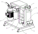
The utility model discloses a special filter equipment for wind-powered electricity generation gear box lubricating oil, the on-line screen storage device comprises a base, the base top is equipped with the support frame, support frame one side fixedly connected with motor pump package, the support frame opposite side is equipped with dark media filter, motor pump package one side is equipped with the oil feed ball valve, the motor pump package opposite side is equipped with balanced charge gathering unit, balanced charge gathering unit and support frame fixed connection, dark media filter top is equipped with the system pressure table. The utility model discloses a joint structure can install fast or dismantle communicating pipe, is favorable to clearing up communicating pipe fast, is favorable to improving filter equipment's filtration efficiency simultaneously, through setting up first sealing ring and second sealing ring, is favorable to improving the leakproofness of communicating pipe, simultaneously through the cooperation of fixture block and extrusion spring, can make connecting cylinder and body continuously be in the extrusion state, is favorable to improving the gas tightness of communicating pipe.
Description
Technical Field
The utility model relates to a filter equipment field, concretely relates to a special filter equipment for wind-powered electricity generation gear box lubricating oil.
Background
The gear box is used as a core component of the wind turbine generator, and is under severe working conditions for a long time, if the indexes of gear oil in the gear box can not reach the standards for a long time, the gear of the fan is easy to generate fatigue wear, adhesive wear, cavitation, fretting wear and the like, so that the fan gear box lubricating oil is subjected to bypass filtration by adopting a mode of combining a BCA balance charge aggregation technology capable of removing submicron particles below 1 mu m and a deep medium filtration technology with high dirt receiving capacity.
However, in practical use, the charge accumulation unit accumulates particle pollutants in the gear oil into clusters, so that pipelines of the charge accumulation unit and the deep medium filter are easy to block, the existing pipeline replacement and cleaning steps are complex, the cleaning efficiency is low, and the normal use of the filtering device is influenced.
Therefore, it is necessary to invent a special filtering device for lubricating oil of a wind power gear box to solve the problems.
Disclosure of Invention
The utility model aims at providing a special filter equipment for wind-powered electricity generation gear box lubricating oil, through the joint structure, can install fast or dismantle communicating pipe, be favorable to clearing up communicating pipe fast, be favorable to improving filter equipment's filtration efficiency simultaneously, through setting up first sealing ring and second sealing ring, be favorable to improving the leakproofness of communicating pipe, the cooperation through fixture block and extrusion spring simultaneously, can make connecting cylinder and body continuously be in the extrusion state, be favorable to improving the gas tightness of communicating pipe, with the above-mentioned weak point in the solution technique.
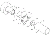
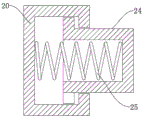
In order to achieve the above object, the present invention provides the following technical solutions: a special filtering device for wind power gear box lubricating oil comprises a base, wherein a supporting frame is arranged at the top of the base, a motor pump group is fixedly connected to one side of the supporting frame, a deep medium filter is arranged at the other side of the supporting frame, an oil inlet ball valve is arranged at one side of the motor pump group, a balance charge gathering unit is arranged at the other side of the motor pump group, the balance charge gathering unit is fixedly connected with the supporting frame, a system pressure gauge is arranged at the top of the deep medium filter, an outlet ball valve is arranged at one side of the bottom of the deep medium filter, a communicating pipe is arranged between the motor pump group and the deep medium filter, the communicating pipe comprises a fixing ring, a connecting cylinder and a pipe body, one side of the fixing ring is fixedly connected with the motor pump group, the other side of, the rotating mechanism comprises a limiting ring, a first arc-shaped block is connected to the outer side of the limiting ring in a sliding manner, a second arc-shaped block is connected to one side of the first arc-shaped block in a sliding manner, accommodating grooves are formed in both the first arc-shaped block and one side of the second arc-shaped block, a reset spring is arranged between the two accommodating grooves and is arranged on the outer side of the limiting ring, the inner side of the first arc-shaped block is fixedly connected with the outer side of the connecting cylinder, the clamping mechanism comprises a first annular plate and a first limiting block, one side of the first annular plate is fixedly connected with the second arc-shaped block, the other side of the first annular plate is fixedly connected with an annular limiting plate, one side of the annular limiting plate is fixedly connected with a second annular plate, a first limiting groove is formed in the surface of the second annular plate, the bottom of the, the inside sliding connection of spout has the fixture block, the draw-in groove has been seted up to the fixture block inside, the inside fixedly connected with extrusion spring of draw-in groove, one side and the draw-in groove inner wall fixed connection that the fixture block is kept away from to the extrusion spring.
Preferably, the number of the first limiting blocks is two, the two first limiting blocks are symmetrically distributed around the central line of the pipe body, the first limiting blocks are matched with the first limiting grooves, and the cross sections of the two ends of each clamping block are arc-shaped.
Preferably, the inside first sealing ring that is equipped with of body, the seal groove has been seted up on first sealing ring surface, the seal groove quantity is established to a plurality ofly, and is a plurality of the seal groove encircles first sealing ring center setting.
Preferably, connecting cylinder one side is equipped with the second sealing ring, second sealing ring one side is equipped with sealed piece, sealed piece quantity is established to a plurality ofly, and is a plurality of sealed piece encircles the setting of second sealing ring center, sealed piece and seal groove phase-match.
Preferably, the outer side of the connecting cylinder is fixedly connected with two second limiting blocks, the number of the second limiting blocks is two, and the two second limiting blocks are symmetrically distributed around the central line of the connecting cylinder.
Preferably, the inner side of the pipe body is provided with two second limiting grooves, the number of the second limiting grooves is two, the two second limiting grooves are symmetrically distributed around the center line of the pipe body, and the second limiting blocks are matched with the second limiting grooves.
In the technical scheme, the utility model provides a technological effect and advantage:
through the joint structure, can install fast or dismantle communicating pipe, be favorable to clearing up communicating pipe fast, be favorable to improving filter equipment's filtration efficiency simultaneously, through setting up first sealing ring and second sealing ring, be favorable to improving the leakproofness of communicating pipe, simultaneously through the cooperation of fixture block with the extrusion spring, can make connecting cylinder and body continuously be in the extrusion state, be favorable to improving the gas tightness of communicating pipe.
Drawings
In order to more clearly illustrate the embodiments of the present application or the technical solutions in the prior art, the drawings needed to be used in the embodiments will be briefly described below, and it is obvious that the drawings in the following description are only some embodiments described in the present invention, and other drawings can be obtained by those skilled in the art according to these drawings.
Fig. 1 is a schematic view of the overall structure of the present invention;
FIG. 2 is a schematic view of the structure of the communication pipe of the present invention;
FIG. 3 is a schematic view of the tube body structure of the present invention;
fig. 4 is a cross-sectional view of the rotating mechanism of the present invention;
figure 5 is the utility model discloses a stopper cross-sectional view.
Description of reference numerals:
1 base, 2 support frames, 3 motor pump package, 4 dark media filter, 5 oil feed ball valves, 6 balanced electric charge gathering unit, 7 system's manometer, 8 export ball valves, 9 communicating pipes, 10 fixed ring, 11 connecting cylinder, 12 bodys, 13 rotary mechanism, 14 latch mechanism, 15 spacing ring, 16 first arc piece, 17 second arc piece, 18 reset spring, 19 first annular plate, 20 first spacing piece, 21 annular limiting plate, 22 second annular plate, 23 first spacing groove, 24 fixture blocks, 25 extrusion spring, 26 first sealing ring, 27 seal groove, 28 second sealing ring, 29 sealed piece, 30 second spacing piece, 31 second spacing groove.
Detailed Description
In order to make the technical solution of the present invention better understood by those skilled in the art, the present invention will be further described in detail with reference to the accompanying drawings.
The utility model provides a special filter equipment for wind power gear box lubricating oil as shown in figures 1-5, which comprises a base 1, the top of the base 1 is provided with a support frame 2, one side of the support frame 2 is fixedly connected with a motor-pump unit 3, the other side of the support frame 2 is provided with a deep medium filter 4, one side of the motor-pump unit 3 is provided with an oil inlet ball valve 5, the other side of the motor-pump unit 3 is provided with a balance charge gathering unit 6, the balance charge gathering unit 6 is fixedly connected with the support frame 2, the top of the deep medium filter 4 is provided with a system pressure gauge 7, one side of the bottom of the deep medium filter 4 is provided with an outlet ball valve 8, a communicating pipe 9 is arranged between the motor-pump unit 3 and the deep medium filter 4, the communicating pipe 9 is composed of a fixing ring 10, a connecting, the other side of the fixing ring 10 is fixedly connected with a connecting cylinder 11, a rotating mechanism 13 is arranged on the outer side of the connecting cylinder 11, a clamping mechanism 14 is arranged on the outer side of the pipe body 12, the rotating mechanism 13 comprises a limiting ring 15, a first arc-shaped block 16 is connected on the outer side of the limiting ring 15 in a sliding manner, a second arc-shaped block 17 is connected on one side of the first arc-shaped block 16 in a sliding manner, accommodating grooves are respectively formed in one sides of the first arc-shaped block 16 and the second arc-shaped block 17, a reset spring 18 is arranged between the two accommodating grooves, the reset spring 18 is arranged on the outer side of the limiting ring 15, the inner side of the first arc-shaped block 16 is fixedly connected with the outer side of the connecting cylinder 11, the clamping mechanism 14 comprises a first annular plate 19 and a first limiting block 20, one side of the first annular plate 19 is fixedly connected with the second arc-shaped block 17, the other side, first spacing groove 23 has been seted up on second annular plate 22 surface, first stopper 20 bottom and body 12 outside fixed connection, the inside spout of having seted up of first stopper 20, the inside sliding connection of spout has fixture block 24, the inside draw-in groove of having seted up of fixture block 24, the inside fixedly connected with extrusion spring 25 of draw-in groove, one side and the draw-in groove inner wall fixed connection that fixture block 24 was kept away from to extrusion spring 25.
Further, in above-mentioned technical scheme, first stopper 20 is established to two in quantity first stopper 20 is about body 12 central line symmetric distribution, first stopper 20 and first spacing groove 23 phase-match, fixture block 24 both ends cross-sectional shape all establishes to the arc, and fixture block 24 both ends cross-sectional shape all establishes to the arc and is favorable to making things convenient for first stopper 20 and first spacing groove 23 looks joint.
Further, in the above technical solution, a first sealing ring 26 is disposed inside the pipe body 12, a sealing groove 27 is formed in the surface of the first sealing ring 26, the number of the sealing grooves 27 is multiple, and the multiple sealing grooves 27 are disposed around the center of the first sealing ring 26.
Further, in the above technical scheme, connecting cylinder 11 one side is equipped with second sealing ring 28, second sealing ring 28 one side is equipped with sealed piece 29, sealed piece 29 quantity is established to a plurality ofly, and is a plurality of sealed piece 29 encircles the central setting of second sealing ring 28, sealed piece 29 and seal groove 27 phase-match are favorable to improving the gas tightness between sealed piece 29 and the seal groove 27.
Further, in the above technical scheme, the outer side of the connecting cylinder 11 is fixedly connected with two second limiting blocks 30, the number of the second limiting blocks 30 is two, and the two second limiting blocks 30 are symmetrically distributed about the central line of the connecting cylinder 11.
Further, in the above technical solution, the inner side of the pipe body 12 is provided with two second limiting grooves 31, the number of the second limiting grooves 31 is two, the two second limiting grooves 31 are symmetrically distributed about the central line of the pipe body 12, the second limiting blocks 30 are matched with the second limiting grooves 31, and the second limiting blocks 30 are matched with the second limiting grooves 31, so that the connection and positioning between the connecting cylinder 11 and the pipe body 12 are facilitated.
This practical theory of operation:
referring to the attached drawings 1-5 of the specification, gear oil can be sucked into a balance charge coalescing unit 6 from an oil inlet ball valve 5 through a motor pump unit 3, submicron particles below 1 micron in the oil are gathered and grown in the unit to form large-particle pollutants, then the large-particle pollutants enter a deep medium filter 4 of the next filtering unit along with the oil, all the large particles larger than 1 micron are intercepted through the deep medium filter 4, and finally the large particles flow out of an outlet ball valve 8, when a communicating pipe 9 needs to be cleaned, a first limiting groove 23 on the surface of a second annular plate 22 is matched with a first limiting block 20 through a rotary annular limiting plate 21, then a pipe body 12 is separated from a connecting cylinder 11 so as to clean the inside of the pipe body 12, when the communicating pipe 9 is installed, the connecting cylinder 11 is inserted into the pipe body 12 through the second limiting block 30 and a second limiting groove 31, meanwhile, the first limiting groove 23 is matched with the second limiting groove 20 by rotating the annular limiting plate 21, the second arc-shaped block 17 is extruded by the reset spring 18, the first annular plate 19 is rotated, the clamping block 24 is extruded with the inner side of the second annular plate 22, the first sealing ring 26 is extruded with the second sealing ring 28, and the sealing block 29 is clamped with the sealing groove 27, so that the installation and the sealing of the communication pipe 9 are completed.
While certain exemplary embodiments of the present invention have been described above by way of illustration only, it will be apparent to those of ordinary skill in the art that the described embodiments may be modified in various different ways without departing from the spirit and scope of the present invention. Accordingly, the drawings and description are illustrative in nature and should not be construed as limiting the scope of the invention.
Claims (6)
1. The utility model provides a special filter equipment for wind-powered electricity generation gear box lubricating oil, includes base (1), its characterized in that: the device is characterized in that a support frame (2) is arranged at the top of the base (1), a motor pump set (3) is fixedly connected to one side of the support frame (2), a deep medium filter (4) is arranged at the other side of the support frame (2), an oil inlet ball valve (5) is arranged at one side of the motor pump set (3), a balanced charge gathering unit (6) is arranged at the other side of the motor pump set (3), the balanced charge gathering unit (6) is fixedly connected with the support frame (2), a system pressure gauge (7) is arranged at the top of the deep medium filter (4), an outlet ball valve (8) is arranged at one side of the bottom of the deep medium filter (4), a communicating pipe (9) is arranged between the motor pump set (3) and the deep medium filter (4), the communicating pipe (9) is composed of a fixing ring (10), a connecting cylinder (11) and a pipe body (, the other side of the fixing ring (10) is fixedly connected with the connecting cylinder (11), a rotating mechanism (13) is arranged on the outer side of the connecting cylinder (11), a clamping mechanism (14) is arranged on the outer side of the pipe body (12), the rotating mechanism (13) comprises a limiting ring (15), a first arc-shaped block (16) is connected on the outer side of the limiting ring (15) in a sliding manner, a second arc-shaped block (17) is connected on one side of the first arc-shaped block (16) in a sliding manner, accommodating grooves are formed in one sides of the first arc-shaped block (16) and the second arc-shaped block (17), a reset spring (18) is arranged between the two accommodating grooves, the reset spring (18) is arranged on the outer side of the limiting ring (15), the inner side of the first arc-shaped block (16) is fixedly connected with the outer side of the connecting cylinder (11), the clamping mechanism (14) comprises a first annular plate (19) and a first limiting block (20), one side of the, first annular slab (19) opposite side fixedly connected with annular limiting plate (21), annular limiting plate (21) one side fixedly connected with second annular slab (22), first spacing groove (23) have been seted up on second annular slab (22) surface, first stopper (20) bottom and body (12) outside fixed connection, the spout has been seted up to first stopper (20) inside, the inside sliding connection of spout has fixture block (24), the draw-in groove has been seted up to fixture block (24) inside, the inside fixedly connected with extrusion spring (25) of draw-in groove, one side and draw-in groove inner wall fixed connection that fixture block (24) were kept away from in extrusion spring (25).
2. The special filtering device for the lubricating oil of the wind power gearbox as claimed in claim 1, wherein: first stopper (20) quantity is established to two, two first stopper (20) are about body (12) central line symmetric distribution, first stopper (20) and first spacing groove (23) phase-match, fixture block (24) both ends cross-sectional shape all is established to the arc.
3. The special filtering device for the lubricating oil of the wind power gearbox as claimed in claim 1, wherein: the sealing device is characterized in that a first sealing ring (26) is arranged inside the pipe body (12), a sealing groove (27) is formed in the surface of the first sealing ring (26), the number of the sealing grooves (27) is set to be multiple, and the sealing grooves (27) are arranged around the center of the first sealing ring (26).
4. The special filtering device for the lubricating oil of the wind power gearbox as recited in claim 3, wherein: connecting cylinder (11) one side is equipped with second sealing ring (28), second sealing ring (28) one side is equipped with sealed piece (29), sealed piece (29) quantity is established to a plurality ofly, and is a plurality of sealed piece (29) encircle second sealing ring (28) center setting, sealed piece (29) and seal groove (27) phase-match.
5. The special filtering device for the lubricating oil of the wind power gearbox as claimed in claim 1, wherein: the connecting cylinder (11) outside fixedly connected with second stopper (30), second stopper (30) quantity is established to two, two second stopper (30) are about connecting cylinder (11) central line symmetric distribution.
6. The special filtering device for the lubricating oil of the wind power gearbox as recited in claim 5, wherein: second spacing grooves (31) are formed in the inner side of the pipe body (12), the number of the second spacing grooves (31) is two, the second spacing grooves (31) are symmetrically distributed about the center line of the pipe body (12), and the second spacing blocks (30) are matched with the second spacing grooves (31).
Priority Applications (1)
| Application Number | Priority Date | Filing Date | Title |
|---|---|---|---|
| CN202022503673.2U CN213655684U (en) | 2020-11-03 | 2020-11-03 | Special filtering device for wind power gear box lubricating oil |
Applications Claiming Priority (1)
| Application Number | Priority Date | Filing Date | Title |
|---|---|---|---|
| CN202022503673.2U CN213655684U (en) | 2020-11-03 | 2020-11-03 | Special filtering device for wind power gear box lubricating oil |
Publications (1)
| Publication Number | Publication Date |
|---|---|
| CN213655684U true CN213655684U (en) | 2021-07-09 |
Family
ID=76705787
Family Applications (1)
| Application Number | Title | Priority Date | Filing Date |
|---|---|---|---|
| CN202022503673.2U Active CN213655684U (en) | 2020-11-03 | 2020-11-03 | Special filtering device for wind power gear box lubricating oil |
Country Status (1)
| Country | Link |
|---|---|
| CN (1) | CN213655684U (en) |
Cited By (1)
| Publication number | Priority date | Publication date | Assignee | Title |
|---|---|---|---|---|
| CN117605825A (en) * | 2024-01-24 | 2024-02-27 | 浙江万里扬股份有限公司杭州分公司 | Lubricating and filtering mechanism of AMT (automated mechanical transmission) |
-
2020
- 2020-11-03 CN CN202022503673.2U patent/CN213655684U/en active Active
Cited By (2)
| Publication number | Priority date | Publication date | Assignee | Title |
|---|---|---|---|---|
| CN117605825A (en) * | 2024-01-24 | 2024-02-27 | 浙江万里扬股份有限公司杭州分公司 | Lubricating and filtering mechanism of AMT (automated mechanical transmission) |
| CN117605825B (en) * | 2024-01-24 | 2024-05-10 | 浙江万里扬股份有限公司杭州分公司 | Lubricating and filtering mechanism of AMT (automated mechanical transmission) |
Similar Documents
| Publication | Publication Date | Title |
|---|---|---|
| CN102151427B (en) | Electrically-driven or hybrid-driven internal rotation cleaning fixed net type collecting device | |
| CN213655684U (en) | Special filtering device for wind power gear box lubricating oil | |
| CN201880435U (en) | Novel portable oil filter | |
| CN206597364U (en) | Spigot-and-socket cripling filter | |
| CN206359261U (en) | A kind of cooling water recirculation system and sealing device | |
| CN201811642U (en) | On-line pollution discharge device of plate-type heat exchanger | |
| CN213977051U (en) | Primary filtering device for water treatment | |
| CN203736947U (en) | Integral cartridge type healthy water device | |
| CN206414989U (en) | A kind of oily oil filter of wire drawing | |
| CN203634936U (en) | Y-shaped filter capable of replacing different drainage plugs | |
| CN102008853A (en) | Novel portable oil filter | |
| CN202700217U (en) | Filter for purified water cooling system | |
| CN209752369U (en) | Nanometer cooling oil processing filter equipment | |
| CN206738260U (en) | A kind of chemical pump filter device | |
| CN221145729U (en) | Low-voltage pulse damper | |
| CN218306949U (en) | Gas pipeline structure with filtering capability | |
| CN212941841U (en) | Primary filtering structure of rainwater retaining module | |
| CN214233070U (en) | Rotary disc filter for sewage treatment | |
| CN218236479U (en) | Pipe connection sealing structure | |
| CN212594283U (en) | Novel angle type filter | |
| CN221131325U (en) | Replaceable multistage multi-medium filter | |
| CN113217477B (en) | Mechanical seal self-flushing device for pump based on Marangoni effect | |
| CN211133161U (en) | Corundum membrane filter tube | |
| CN218485363U (en) | Pipeline filter | |
| CN210814173U (en) | Dry oil filter |
Legal Events
| Date | Code | Title | Description |
|---|---|---|---|
| GR01 | Patent grant | ||
| GR01 | Patent grant |