CN213645462U - Bidirectional bending machine for plate processing - Google Patents
Bidirectional bending machine for plate processing Download PDFInfo
- Publication number
- CN213645462U CN213645462U CN202022379936.3U CN202022379936U CN213645462U CN 213645462 U CN213645462 U CN 213645462U CN 202022379936 U CN202022379936 U CN 202022379936U CN 213645462 U CN213645462 U CN 213645462U
- Authority
- CN
- China
- Prior art keywords
- bending
- piece
- clamping
- guide
- fixing member
- Prior art date
- Legal status (The legal status is an assumption and is not a legal conclusion. Google has not performed a legal analysis and makes no representation as to the accuracy of the status listed.)
- Active
Links
Images


Landscapes
- Bending Of Plates, Rods, And Pipes (AREA)
Abstract
The utility model discloses a panel processing is with bender of two-way bending belongs to the bender field. The automatic bending machine comprises a frame, wherein a working platform is fixedly arranged on the frame and horizontally arranged, a first driving piece is arranged on the frame on the front side of the working platform, the output end of the first driving piece is connected with a pressing piece, a second driving piece is arranged on the frame in front of the working platform, the output end of the second driving piece is fixedly connected with an installation mechanism, and two bending pieces which are oppositely arranged are arranged on the installation mechanism. Adopt two processing methods of bending, two pieces of bending set up respectively in work platform's top and below, driving piece two realizes reciprocating of two pieces of bending through three working stroke, initial working stroke is that the symmetry axis of two pieces of bending flushes with work platform's plane, one is the working stroke of the downstream of the piece of bending, another is the working stroke of the upstream of the piece of bending down, the work of bending of station about the comprehensive utilization can realize, improve equipment's work efficiency greatly.
Description
Technical Field
The utility model relates to a technical field of bender especially relates to a bender that processing panel that can two-way bend was used.
Background
The bending machine is a workpiece which bends a metal plate in a cold state into various geometric cross-sectional shapes by using an equipped die (a general-purpose or special-purpose die). The sheet forming machine is designed for cold-rolled sheet metal processing, and is widely applied to bending and processing of sheets in the industries of automobile, aircraft manufacturing, light industry, shipbuilding, containers, elevators, railway vehicles and the like.
The existing traditional bending machine is basically processed in a single direction, and if the traditional bending machine is used for processing in multiple directions, the workpiece needs to be manually changed in direction once. When the existing bending machine bends the plates, a technical problem generally exists: because the finished product is complicated diversified structurally, the large trend development of high strength and small space is satisfied by bending in multiple directions, and the existing mode processing is adopted at the moment, so that the processing efficiency can be greatly influenced, and the cost can not be reduced to an ideal value.
Disclosure of Invention
The utility model aims at solving the problem that the prior art is not enough, so the utility model provides a panel processing is with bender of two-way bending.
In order to achieve the above purpose, the utility model adopts the following technical scheme:
the utility model provides a panel processing is with bender of two-way bending, includes the frame, fixed mounting has the work platform that the level set up in the frame, is located the work platform front side install driving piece one in the frame, the output of driving piece one is connected with and compresses tightly the piece, is located work platform the place ahead install driving piece two in the frame, the output fixedly connected with installation mechanism of driving piece two, install the piece of bending of two relative settings on the installation mechanism.
Further preferably, one side of the bending piece opposite to the bending piece is provided with a horizontal section and an arc-shaped section, and the horizontal section is positioned on one side of the arc-shaped section far away from the working platform.
Further preferably, installation mechanism includes mounting, guide, buffer spring, clamping piece and regulating part, mounting fixed connection is on the output of driving piece two, the top of mounting and the equal fixed connection in bottom of mounting have the guide that the level set up, two all the cover is equipped with buffer spring on the guide, the clamping piece is equipped with two and slides respectively and sets up on the guide that corresponds and be located one side that buffer spring kept away from the mounting, two the constant head tank has all been seted up to one side that buffer spring was kept away from to the clamping piece, the regulating part is equipped with two and rotates respectively to connect and keeps away from the one end of mounting and be located one side that corresponding clamping piece is kept away from buffer spring at corresponding guide, two the constant head tank respectively with the regulating part looks adaptation that corresponds.
Further preferably, two the constant head tank is the arc structure, and two regulating part all includes cam portion and the handle portion of body coupling, two cam portion is eccentric connection respectively on the guide that corresponds, two all seted up the spacing groove on the clamping piece, two the spacing inslot portion all is equipped with elasticity and presss from both sides tight piece and is used for restricting handle portion lateral rotation.
Further preferably, two mounting grooves are formed in one side, opposite to the fixing piece, of the clamping piece, compression springs and compression strips are mounted inside the two mounting grooves, one side of each compression strip is connected with one end of each compression spring, and the other side of each compression strip extends to the outer side of each mounting groove.
Further preferably, a balance structure is arranged on the clamping piece and comprises a guide part and a buffer part, one end of the guide part is fixedly connected to the clamping piece, the other end of the guide part freely penetrates through the fixing piece, and the buffer part is sleeved on the guide part between the clamping piece and the fixing piece.
Further preferably, one side that work platform kept away from the piece of bending installs feeding mechanism, feeding mechanism includes driving motor, gear, slide and pneumatic clamping jaw, driving motor fixed mounting is on work platform's lateral wall, driving motor's output fixed mounting has the gear, the slide slides and sets up on work platform and forms transmission cooperation with the gear.
Compared with the prior art, the utility model discloses possess following beneficial effect:
1. the utility model discloses a two processing methods of bending, two pieces of bending set up respectively in work platform's top and below, two reciprocating of realizing two pieces of bending through three working stroke of driving piece, the initial working stroke flushes for the symmetry axis of two pieces of bending and work platform's plane, a work stroke for last a downstream of bending, another is the working stroke of the downstream of bending down, the work of bending of station about the comprehensive utilization can be realized, improve equipment's work efficiency greatly.
2. The utility model discloses well positioning mechanism includes mounting, clamping piece, guide, buffer spring and regulating part, removes the clamping piece to one side that is close to the mounting along the guide through adjusting the regulating part, realizes pressing from both sides the effect of tightly bending, and the constant head tank on the clamping piece realizes the effect of ann tearing open fast with regulating part looks adaptation simultaneously, improves the maintenance efficiency of bender greatly.
3. The utility model discloses well balanced structure who is equipped with includes guide part and buffering portion, can prevent through the guide part that the tight piece atress of clamp from inclining partially, and then reduces the side direction stress, and buffering portion can reduce the damage of clamping piece fifty percent discount spare simultaneously, improves the security of bender.
4. The utility model discloses in still be equipped with feeding mechanism, drive gear drive through driving motor, the gear drives the slide and removes to one side that is close to the piece of bending, and pneumatic clamping jaw on it can press from both sides panel tightly and feed to one side of bending along with the slide, and pneumatic clamping jaw can guarantee that panel remains higher ground stability throughout when feeding to one side of bending.
Drawings
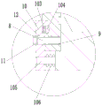
Fig. 1 is a schematic view of the overall structure of the present invention;
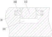
FIG. 2 is an enlarged view of a portion of FIG. 1 at A;
FIG. 3 is a cross-sectional view of a clamping member according to the present invention;
FIG. 4 is a cross-sectional view taken at B-B of FIG. 3;
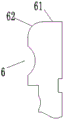
fig. 5 is a partial schematic view of a bending member in the present invention.
In the figure: 1. a frame; 2. a working platform; 3. a first driving part; 4. a compression member; 5. a driving part II; 6. bending a piece; 61. a horizontal segment; 62. an arc-shaped section; 7. a fixing member; 8. a guide member; 9. a buffer spring; 10. a clamping member; 101. a limiting groove; 102. an elastic clamping block; 103. mounting grooves; 104. compressing the strips; 105. a guide portion; 106. a buffer section; 11. an adjustment member; 111. a cam portion; 112. a handle portion; 12. positioning a groove; 13. a drive motor; 14. a gear; 15. a slide plate; 16. pneumatic clamping jaw.
Detailed Description
The technical solutions in the embodiments of the present invention will be described clearly and completely with reference to the accompanying drawings in the embodiments of the present invention, and it is obvious that the described embodiments are only some embodiments of the present invention, not all embodiments.
In the description of the present invention, it is to be understood that the terms "upper", "lower", "front", "rear", "left", "right", "top", "bottom", "inner", "outer", and the like indicate orientations or positional relationships based on the orientations or positional relationships shown in the drawings, and are only for convenience of description and simplicity of description, and do not indicate or imply that the device or element being referred to must have a particular orientation, be constructed and operated in a particular orientation, and therefore, should not be construed as limiting the present invention.
Example 1:
as shown in fig. 1 to 5, a bending machine for bidirectional bending for plate processing comprises a frame 1, wherein a working platform 2 is fixedly mounted on the frame 1 and horizontally arranged, the working platform is located on the front side of the working platform 2, a first driving piece 3 (electric push rod) is mounted on the frame 1, an output end of the first driving piece 3 is connected with a pressing piece 4, the first driving piece 2 is located above the front side of the working platform 2, a second driving piece 5 (hydraulic cylinder) is mounted on the frame 1, an output end of the second driving piece 5 is fixedly connected with a mounting mechanism, and two bending pieces 6 which are oppositely arranged are mounted on the mounting mechanism. When the workpiece bending machine is used, a workpiece is placed on the working platform 2, the output end of the first driving piece 3 pushes the pressing piece 4 downwards to press the workpiece, and the output end of the second driving piece 5 drives the bending piece 6 above to move downwards or the bending piece 6 below to move upwards, so that bidirectional bending of the workpiece is achieved, and the machining efficiency is greatly improved.
Further preferably, a horizontal section 61 and an arc-shaped section 62 are arranged on one side, opposite to the bending piece 6, of the bending piece, and the horizontal section 61 is located on one side, far away from the working platform 2, of the arc-shaped section 62. The horizontal section 61 is firstly contacted with the workpiece and then is used for conventional bending through the arc-shaped section 62, so that the workpiece is prevented from being damaged when the workpiece is bent by the bending piece 6.
Further preferably, the mounting mechanism comprises a fixing member 7, a guide member 8, a buffer spring 9, a clamping member 10 and an adjusting member 11, the fixed part 7 is fixedly connected with the output end of the second driving part 5, the top and the bottom of the fixed part 7 are fixedly connected with horizontally arranged guide parts 8, buffer springs 9 are sleeved on the two guide parts 8, the clamping pieces 10 are provided with two positioning grooves 12 which are respectively arranged on the corresponding guide pieces 8 in a sliding manner and are positioned on one sides of the buffer springs 9 far away from the fixing piece 7, one sides of the two clamping pieces 10 back to the buffer springs 9 are both provided with positioning grooves 12, the adjusting piece 11 is provided with two positioning grooves 12 which are respectively rotatably connected to one end of the corresponding guide piece 8 far away from the fixing piece 7 and are positioned on one side of the corresponding clamping piece 10 back to the buffer spring 9, and the two positioning grooves 12 are respectively matched with the corresponding adjusting piece 11. Realize through regulating part 11 and constant head tank 12 that clamping piece 10 moves and presss from both sides tightly the piece 6 of bending to one side that is close to mounting 8, when the piece 6 of bending that needs to be changed, only need to separate regulating part 11 and constant head tank 12, clamping piece 10 will move to one side of keeping away from mounting 7 under buffer spring 9's effect for separate with the piece 6 of bending, carry out quick replacement.
Further preferably, the two positioning grooves 12 are both arc-shaped structures, the two adjusting members 11 each include a cam portion 111 and a handle portion 112 that are integrally connected, the two cam portions 111 are respectively eccentrically connected to the corresponding guide members 8, two clamping members 10 are each provided with a limiting groove 101, and an elastic clamping block 102 is arranged inside each limiting groove 101 and used for limiting the handle portion 112 to rotate outwards. The eccentric arrangement of the cam part 111 enables a section of displacement to occur when the cam part is matched with the positioning groove 12, so that the clamping part 10 moves towards one side close to the fixing part 7 to press and fix the bending part 6, and meanwhile, the position of the handle part 112 is limited under the action of the elastic clamping block 102, and safety accidents in the bending process are avoided.
Further preferably, two opposite sides of the fixing member 7 of the clamping member 10 are respectively provided with a mounting groove 103, a compression spring and a compression bar 104 are respectively mounted inside the two mounting grooves 103, one side of the compression bar 104 is connected with one end of the compression spring, and the other side of the compression bar extends to the outer side of the mounting groove 103. The pressing strip 104 arranged on the clamping part 10 can press the bending part 6 in an auxiliary way when pressing the bending part 6, so that the bending quality is prevented from being influenced by position deviation.
Further preferably, a balance structure is arranged on the clamping member 10, the balance structure includes a guide portion 105 and a buffer portion 106, one end of the guide portion 105 is fixedly connected to the clamping member 10, the other end of the guide portion freely penetrates through the fixing member 7, and the buffer portion 106 is sleeved on the guide portion 105 located between the clamping member 10 and the fixing member 7. Utilize guide part 105 and buffer 106 to make clamping piece 10 all can steady removal when compressing tightly the piece 6 of bending and unclamping the piece 6 of bending, prevent that it from appearing the skew and producing stress, and then guarantee the stability and the reliability of whole bender.
Example 2:
as shown in fig. 1, on the basis of embodiment 1, a feeding mechanism is further preferably installed on one side of the working platform 2, which is far away from the bending piece 6, and the feeding mechanism includes a driving motor 13, a gear 14, a sliding plate 15 and a commercially available pneumatic clamping jaw 16, the driving motor 13 is fixedly installed on a side wall of the working platform 2, the gear 14 is fixedly installed at an output end of the driving motor 13, the sliding plate 15 is slidably disposed on the working platform 2 and forms transmission fit with the gear 14, the pneumatic clamping jaw 16 is fixedly installed on the sliding plate 15, and the distance of forward movement or backward movement of the sliding plate 15 can be accurately controlled by controlling the number of rotations of the output end of the driving motor 13 and related parameters of the gear 14, so as to ensure the precision of the machined surface.
The utility model discloses can operate like this when concrete implementation, at first prevent with work piece panel that work piece 2 and through pneumatic clamping jaw 16 with the panel work piece fixed, driving motor 13 drives slide 15 and panel work piece through gear 14 afterwards and removes to being close to 6 one side of bending, after removing to suitable position, driving piece one 3 drives and compresses tightly 4 downstream and compress tightly the panel work piece, driving piece two 5 drive bending 6 from top to bottom to the panel work piece both-way bending afterwards. When the bending piece 6 is assembled and disassembled, the eccentric cam part 111 is separated from the positioning groove 12 after the handle part 112 is separated from the elastic clamping block 102, so that the bending piece 6 is clamped, otherwise, the bending piece 6 is loosened.
The above description is only a preferred embodiment of the present invention, but the scope of the present invention is not limited thereto. The substitution may be of partial structures, devices, method steps, or may be a complete solution. According to the technical scheme of the utility model and utility model thereof think of and equal replacement or change, all should cover within the scope of protection of the utility model.
Claims (7)
1. The utility model provides a panel processing is with bender of two-way bending, a serial communication port, including frame (1), work platform (2) that fixed mounting has the level to set up are located work platform (2) front side install driving piece (3) on frame (1), the output of driving piece (3) is connected with compresses tightly piece (4), is located work platform (2) the place ahead install driving piece two (5) on frame (1), the output fixedly connected with installation mechanism of driving piece two (5), install the piece of bending (6) of two relative settings on the installation mechanism.
2. The bending machine for bidirectionally bending plates according to claim 1, wherein a horizontal segment (61) and an arc segment (62) are arranged on opposite sides of said bending member (6), and said horizontal segment (61) is located on one side of said arc segment (62) far away from said working platform (2).
3. The bending machine for bidirectionally bending plates according to claim 1, wherein the mounting mechanism comprises a fixing member (7), two guide members (8), two buffer springs (9), two clamping members (10) and an adjusting member (11), the fixing member (7) is fixedly connected to the output end of the second driving member (5), the top and the bottom of the fixing member (7) are fixedly connected with the horizontally arranged guide members (8), the two guide members (8) are sleeved with the buffer springs (9), the two clamping members (10) are provided with two positioning grooves (12) which are respectively slidably arranged on the corresponding guide members (8) and located on one side of the buffer springs (9) far away from the fixing member (7), the two clamping members (10) are respectively provided with one side back to the buffer springs (9), the adjusting member (11) is provided with two positioning grooves (12) which are respectively rotatably connected to one end of the corresponding guide member (8) far away from the fixing member (7) and located on one side of the corresponding clamping member (11) (10) And two positioning grooves (12) are respectively matched with corresponding adjusting pieces (11) at one side back to the buffer spring (9).
4. The bending machine for bidirectionally bending plates according to claim 3, wherein each of the two positioning grooves (12) has an arc-shaped structure, each of the two adjusting members (11) comprises a cam portion (111) and a handle portion (112) which are integrally connected, each of the two cam portions (111) is eccentrically connected to the corresponding guide member (8), each of the two clamping members (10) is provided with a limiting groove (101), and each of the two limiting grooves (101) is internally provided with an elastic clamping block (102) for limiting the handle portion (112) from rotating outwards.
5. The bending machine for bidirectionally bending plates for processing plates according to claim 3, wherein one side of each of the two clamping members (10) opposite to the fixing member (7) is provided with a mounting groove (103), a compression spring and a pressing strip (104) are mounted inside each of the two mounting grooves (103), one side of the pressing strip (104) is connected with one end of the compression spring, and the other side of the pressing strip extends to the outer side of the mounting groove (103).
6. The bending machine for bidirectionally bending plates according to claim 3, wherein the clamping member (10) is provided with a balance structure, the balance structure comprises a guide part (105) and a buffer part (106), one end of the guide part (105) is fixedly connected to the clamping member (10) and the other end of the guide part freely penetrates through the fixing member (7), and the buffer part (106) is sleeved on the guide part (105) between the clamping member (10) and the fixing member (7).
7. The bending machine for bidirectionally bending plates according to claim 1, wherein a feeding mechanism is installed on one side of the working platform (2) far away from the bending piece (6), the feeding mechanism comprises a driving motor (13), a gear (14), a sliding plate (15) and a pneumatic clamping jaw (16), the driving motor (13) is fixedly installed on the side wall of the working platform (2), the gear (14) is fixedly installed at the output end of the driving motor (13), and the sliding plate (15) is slidably arranged on the working platform (2) and forms a transmission fit with the gear (14).
Priority Applications (1)
| Application Number | Priority Date | Filing Date | Title |
|---|---|---|---|
| CN202022379936.3U CN213645462U (en) | 2020-10-23 | 2020-10-23 | Bidirectional bending machine for plate processing |
Applications Claiming Priority (1)
| Application Number | Priority Date | Filing Date | Title |
|---|---|---|---|
| CN202022379936.3U CN213645462U (en) | 2020-10-23 | 2020-10-23 | Bidirectional bending machine for plate processing |
Publications (1)
| Publication Number | Publication Date |
|---|---|
| CN213645462U true CN213645462U (en) | 2021-07-09 |
Family
ID=76703711
Family Applications (1)
| Application Number | Title | Priority Date | Filing Date |
|---|---|---|---|
| CN202022379936.3U Active CN213645462U (en) | 2020-10-23 | 2020-10-23 | Bidirectional bending machine for plate processing |
Country Status (1)
| Country | Link |
|---|---|
| CN (1) | CN213645462U (en) |
Cited By (1)
| Publication number | Priority date | Publication date | Assignee | Title |
|---|---|---|---|---|
| CN114210778A (en) * | 2021-12-13 | 2022-03-22 | 忠通(广州)环保机械有限公司 | Steel sheet bender is used in steel construction processing |
-
2020
- 2020-10-23 CN CN202022379936.3U patent/CN213645462U/en active Active
Cited By (2)
| Publication number | Priority date | Publication date | Assignee | Title |
|---|---|---|---|---|
| CN114210778A (en) * | 2021-12-13 | 2022-03-22 | 忠通(广州)环保机械有限公司 | Steel sheet bender is used in steel construction processing |
| CN114210778B (en) * | 2021-12-13 | 2024-02-23 | 忠通(广州)环保机械有限公司 | Steel sheet bender is used in steel construction processing |
Similar Documents
| Publication | Publication Date | Title |
|---|---|---|
| CN1321785C (en) | Apparatus for blanking and processing profile notches of rubber sealing strip | |
| CN213645448U (en) | Bending machine tool with adjustable bending angle | |
| CN102825180B (en) | Cutter holder-integrated spring coiling machine | |
| CN212239043U (en) | Spring autoloading coiling shaping cutting device | |
| CN113458802B (en) | Special preparation system and preparation method for safe type automobile guide arm frame support | |
| CN213645462U (en) | Bidirectional bending machine for plate processing | |
| CN214022738U (en) | Angle-adjustable numerical control bending machine | |
| CN219378605U (en) | Punching machine | |
| CN219233759U (en) | Clamping device for bending machine | |
| CN217223068U (en) | Bending machine | |
| CN202877456U (en) | Tool rest integrated spring coiling machine | |
| CN212168648U (en) | Bending forming machine for automobile exhaust system parts | |
| CN210525119U (en) | Pneumatic mechanical arm clamping device | |
| CN212704046U (en) | Numerical control bending machine | |
| CN217617369U (en) | A punch press work piece positioner for casing | |
| CN111069379A (en) | Shaping processing equipment and processing method for sheet metal part of new energy automobile after forming | |
| CN220717393U (en) | U-shaped bolt forming device | |
| CN219817580U (en) | Numerical control bending machine convenient for adjusting bending angle | |
| CN221587693U (en) | Cable auxiliary winding bracket | |
| CN213256738U (en) | Novel bending machine | |
| CN218283360U (en) | Automatic stamping equipment combination frock | |
| CN218191901U (en) | Carriage indentation device | |
| CN218364256U (en) | Executor cylinder body shaft hole processing frock | |
| CN220805036U (en) | Aluminum alloy plate bending device | |
| CN216398885U (en) | Pliers processing machine tool with positioning mechanism |
Legal Events
| Date | Code | Title | Description |
|---|---|---|---|
| GR01 | Patent grant | ||
| GR01 | Patent grant |