CN213623271U - Mechanical mattress surface fabric surfacing machine - Google Patents
Mechanical mattress surface fabric surfacing machine Download PDFInfo
- Publication number
- CN213623271U CN213623271U CN202022351449.6U CN202022351449U CN213623271U CN 213623271 U CN213623271 U CN 213623271U CN 202022351449 U CN202022351449 U CN 202022351449U CN 213623271 U CN213623271 U CN 213623271U
- Authority
- CN
- China
- Prior art keywords
- mattress
- fabric
- centre gripping
- limiting bolt
- limiting
- Prior art date
- Legal status (The legal status is an assumption and is not a legal conclusion. Google has not performed a legal analysis and makes no representation as to the accuracy of the status listed.)
- Active
Links
Images


Landscapes
- Treatment Of Fiber Materials (AREA)
Abstract
The utility model discloses a machinery mattress surface fabric shop front, including assisting a workstation the left and right sides of assisting a workstation is provided with the centre gripping subassembly of symmetry respectively centre gripping subassembly's below is provided with nail rifle device, the centre gripping subassembly is used for right the mattress is assisting a in-process and is carrying out the rigidity and carry out the surface fabric to the mattress surface and assist a face operation, nail rifle device is used for carrying out the rigidity to the mattress and the surface fabric after assisting a face. The utility model discloses a centre gripping mattress's centre gripping subassembly, messenger's surface fabric are stretching of tight laminating mattress and draw the mechanism and make the surface fabric bind in the nail rifle device of mattress, all accomplish under the whole shop front process of mattress is in the fixed state on the centre gripping subassembly, avoid the upset, remove and lead to the mattress to produce the collision damage.
Description
Technical Field
The utility model relates to a mattress production technical field, concretely relates to mechanical mattress surface fabric shop front machine.
Background
In the current furniture industry, leather, cloth art and the like are wrapped and inlaid on various soft furniture cushions, a traditional manual paving mode is usually adopted, however, the traditional manual paving mode needs workers to position and press the leather, the cloth art and the like through self strength, when the turnups of the leather, the cloth art and the like are fixed by the workers, one hand presses the turnups of the leather, the cloth art and the like, and then the other hand is used for nailing and fixing, so that physical power is consumed, the processing difficulty is increased, and the labor intensity is high.
Therefore, patent CN111559733A discloses an efficient seatpad shop front equipment, including the mounting plate that is used for settling the seatpad, a fixed subassembly of the surface fabric that is used for launching the surface fabric tight, a frame for forming the fixed frame to the seatpad, all insert in the fixed frame and be equipped with a plurality of thin slices, the thin slice bottom surface articulates there is the turn-ups piece, the width of turn-ups piece reduces to the free end by the one end of being connected with the thin slice gradually, when the turn-ups piece is suppressed in the seatpad back, form the rifle nail portion between the adjacent turn-ups piece, the turn-ups piece is equipped with bar magnet along its length direction, be equipped with the electro-magnet in the mounting plate, this application can be used to shop front the seatpad to various shapes, the size, application scope is wide, simultaneously through the setting of turn-ups piece, can be even with the surface fabric, neatly fold the seatpad back.
Although the patent CN111559733A realizes mechanical automation paving, which does improve production efficiency, there are certain drawbacks: (1) the whole operation process needs clamping, skin cutting, flanging and nailing, the process is complex, the mattress needs to be turned and moved ceaselessly, and the mattress is difficult to prevent from being damaged due to physical collision in the moving process of the mattress; (2) in the process of wrapping the fabric on the mattress in the operation process, the specification of measuring the fit degree of the fabric and the mattress is lacked, the uniformity of the tightness of the fabric cannot be ensured, the product is uneven and uniform in the process of mass manufacturing, and the overall quality is poor.
SUMMERY OF THE UTILITY MODEL
An object of the utility model is to provide a mechanical mattress surface fabric shop front machine to the upset that does not stop that needs among the solution prior art removes the mattress, is difficult to prevent at the removal in-process of mattress that the physics collision leads to the mattress damage, lacks the standard of weighing surface fabric and mattress laminating degree, can't guarantee the unified technical problem of the tight degree of surface fabric.
In order to solve the above technical problem, the utility model particularly provides the following technical scheme:
a mechanical mattress facing machine comprises a facing workbench, wherein symmetrical clamping assemblies are respectively arranged on the left side and the right side of the facing workbench, a nail gun device is arranged below the clamping assemblies, the clamping assemblies are used for fixing the position of a mattress in the facing process and performing facing operation on the surface of the mattress, and the nail gun device is used for fixing the position of the mattress and a facing after facing;
the centre gripping subassembly is including setting up assisting left holder on face workstation and setting assisting right holder on face workstation right side, left side holder towards assist face workstation center side have with the same left centre gripping groove of left side shape of mattress, right side holder towards assist face workstation center side have with the same right centre gripping groove of right side shape of mattress, left side centre gripping groove and right centre gripping groove combination form the centre gripping space that supplies the mattress to fix.
As the utility model discloses a preferred scheme left side centre gripping groove and right centre gripping groove orientation are assisted the center side of face workstation and all are provided with and stretch and draw the mechanism, both sides stretch and draw the mechanism and be close to each other and be used for being the laminating of tight state on the mattress surface with the surface fabric of parcel on the mattress.
As a preferred scheme of the utility model, stretch and draw the mechanism including setting up the power device at left centre gripping groove and right centre gripping groove front end, power device's front end all is provided with the ejector pin, the one end of ejector pin links to each other with power device's transmission shaft, the other end with fix the surface fabric edge at the mattress lower surface.
As an optimal scheme of the utility model the both ends department of surface fabric is provided with spacing hole, the ejector pin is fixed and is served and be provided with the spacing bolt with spacing hole assorted under the mattress surface fabric surface, the structure of combining into simultaneous movement with ejector pin, surface fabric in the spacing hole of embedding in the spacing bolt.
As a preferred scheme of the utility model, be connected through the electromagnetism mode between spacing bolt and the ejector pin, ejector pin and spacing bolt position department that links to each other are nested at the annular electromagnetic means of spacing bolt peripheral part, the circular telegram annular electromagnetic means has the appeal to the spacing bolt, the spacing bolt is in keep having no position change's an organic whole structure with annular electromagnetic means under the effect of the attraction force.
As a preferred scheme of the utility model, spacing bolt is tip formula external diameter crescent structure, the internal diameter in spacing hole is the same with spacing bolt mid portion external diameter to spacing bolt inlays from the tip portion in going into spacing hole, the biggest external diameter of spacing bolt is the same with annular electromagnetic means's internal diameter.
As a preferred scheme of the utility model the upper portion in left side centre gripping groove and right centre gripping groove is provided with laser emitter and laser receiver respectively, laser emitter and laser receiver are located same water flat line, laser emitter is to the linear laser of laser receiver transmission, laser receiver is used for receiving linear laser, linear laser is located the laminating degree that the mattress upper surface is used for standardizing the surface fabric on the mattress surface.
As an optimal scheme of the utility model, the nail rifle device is including setting up the climbing mechanism in annular electromagnetic means below and setting up at the removable nail post in climbing mechanism top, the one end of nail post links to each other with the jacking axle of climbing device, and the other end contacts with the stop cock lower surface, climbing mechanism drives the nail post and breaks away from the linear nail of annular electromagnetic means with the stop cock and goes into the mattress lower surface and make the fixed parcel of surface fabric on the mattress surface.
As an optimized proposal of the utility model, the outer diameter of the nail post is consistent with the inner diameter of the annular electromagnetic device.
Compared with the prior art, the utility model following beneficial effect has:
(1) the utility model comprises a clamping component for clamping the mattress, a stretching mechanism for making the fabric tightly fit the mattress and a nail gun device for nailing the fabric on the mattress, the whole paving process of the mattress is finished under the fixed state on the clamping component, and the mattress is prevented from collision and damage caused by overturning and moving;
(2) the utility model discloses be provided with the surface fabric that laser emitter and laser receiver constitute and the standard mechanism of the tight laminating degree of mattress to the cooperation has stretching of the tight degree of adjustable surface fabric to draw the mechanism and carry out the tight degree of fabric and adjust, can effectually guarantee the unity of the tight degree of surface fabric in each mattress, and production standardization is high.
Drawings
In order to more clearly illustrate the embodiments of the present invention or the technical solutions in the prior art, the drawings used in the description of the embodiments or the prior art will be briefly described below. It should be apparent that the drawings in the following description are merely exemplary, and that other embodiments can be derived from the drawings provided by those of ordinary skill in the art without inventive effort.
Fig. 1 is a schematic view of an overall structure provided by an embodiment of the present invention;
fig. 2 is a schematic top view of the left clamping member according to the embodiment of the present invention;
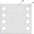
fig. 3 is a schematic view of a fabric structure provided by an embodiment of the present invention;
fig. 4 is a schematic view of a fabric bulge linear laser propagation structure provided by the embodiment of the present invention;
fig. 5 is a schematic view of a fabric-tightening laser propagation structure provided by the embodiment of the present invention.
The reference numerals in the drawings denote the following, respectively:
1-auxiliary surface workbench; 2-a clamping assembly; 3-a nail gun device; 4-stretching the mechanism; 5-limiting holes; 6-a laser emitter; 7-a laser receiver; 8, a mattress; 9-fabric; 10-linear laser;
201-left clamp; 202-right clamp; 203-left clamping groove; 204-right clamping groove;
301-a jacking mechanism; 302-nail column;
401-a power plant; 402-a mandril; 403-limit bolt; 404-ring-shaped electromagnetic device.
Detailed Description
The technical solutions in the embodiments of the present invention will be described clearly and completely with reference to the accompanying drawings in the embodiments of the present invention, and it is obvious that the described embodiments are only some embodiments of the present invention, not all embodiments. Based on the embodiments in the present invention, all other embodiments obtained by a person skilled in the art without creative work belong to the protection scope of the present invention.
As shown in fig. 1-3, the utility model provides a machinery mattress surface fabric shop front machine, including the wainscot workstation 1, be provided with the centre gripping subassembly 2 of symmetry respectively in the left and right sides of wainscot workstation 1, be provided with nail rifle device 3 in the below of centre gripping subassembly 2, centre gripping subassembly 2 is used for carrying out the rigidity to the mattress in the wainscot process and carries out the surface fabric wainscot operation to the mattress surface, and nail rifle device 3 is used for carrying out the rigidity to the mattress and the surface fabric behind the wainscot.
Mattress surface fabric can be cotton material, linen, cladding or other kind of materials in this embodiment to in order to shop front convenience and the uniformity of the specification of surface fabric, the surface fabric in this embodiment is the realization through tailor the same tailorring of device, and has seted up spacing hole 5 on the periphery of surface fabric.
The clamping assembly 2 comprises a left clamping piece 201 arranged on the left side of the assistant surface workbench 1 and a right clamping piece 202 arranged on the right side of the assistant surface workbench 1, the left clamping piece 201 is provided with a left clamping groove 203 which is the same as the left side shape of a mattress towards the center side of the assistant surface workbench 1, the right clamping piece 202 is provided with a right clamping groove 204 which is the same as the right side shape of the mattress towards the center side of the assistant surface workbench 1, and the left clamping groove 203 and the right clamping groove 204 are combined to form a clamping space for fixing the mattress.
The mattress is placed in the centre gripping space from the top under the effect of external force, and left side and the bottom surface of left centre gripping groove 203 and mattress contact, and right centre gripping groove 204 contacts with the right side and the bottom surface of mattress to left clamping piece 201 and right clamping piece 202 have formed horizontal and fore-and-aft position to the mattress and have prescribed a limit to, prevent to appear the position removal at subsequent surface fabric parcel in-process, and the top in centre gripping space is used for laying the surface fabric for the opening form.
Stretching mechanisms 4 are arranged on the center sides of the left clamping groove 203 and the right clamping groove 204 facing the auxiliary surface workbench 1, and the stretching mechanisms 4 on the two sides are close to each other and used for attaching the fabric wrapped on the mattress to the surface of the mattress in a tight state.
The stretching mechanism 4 comprises a power device 401 arranged at the front ends of the left clamping groove 203 and the right clamping groove 204, the front ends of the power devices 401 are respectively provided with a top bar 402, one end of the top bar 402 is connected with a transmission shaft of the power device 401, and the other end of the top bar 402 is fixed at the edge of the fabric on the lower surface of the mattress.
Wherein, power device 401 is pneumatic cylinder, cylinder or other axial telescopic parts that have the same function, because the both ends of ejector pin 402 are connected with power device 401's transmission shaft and surface fabric edge respectively, keeps synchronous telescopic state with surface fabric edge and power device 401's transmission shaft, and the fabric is tight to be laminated the concrete process of mattress and is: the transmission shafts of two power devices 401 positioned on the left clamping groove 203 and the right clamping groove 204 are controlled to drive the ejector rods 402 to push and extend forwards, the ejector rods 402 drive the edges of the fabric to stretch forwards, so that the middle part of the fabric is gradually stretched and tightened along with the stretching of the edges, and all parts of the fabric wrapped on the surface of the mattress are attached to the surface of the mattress in a consistent and tight state.
In order to keep the edge of the fabric to be uniformly and neatly stretched and pulled, the two ends of the fabric are provided with the limiting holes 5, the limiting holes 5 are linearly arranged at the edge of the fabric, one end of the ejector rod 402, which is fixed on the surface of the fabric on the lower surface of the mattress, is provided with the limiting bolt 403 matched with the limiting holes 5, the limiting bolt 403 is embedded into the limiting hole 5 to combine the ejector rod 402 and the fabric into a synchronous motion structure, and the limiting bolt 403 and the ejector rod 402 keep a consistent motion state, so that the forward stretching speed of each part of the edge line of the fabric is determined by the limiting bolt 403, and because the limiting bolt 403 and the limiting holes 5 are linearly arranged at the edge of the fabric, the linearly arranged limiting holes 5 keep the synchronous motion state of each part of the edge of the fabric to be integrally and neatly linear stretching under the regulation.
The limit bolt 403 is connected with the ejector rod 402 in an electromagnetic way, the position where the ejector rod 402 is connected with the limit bolt 403 is an annular electromagnetic device 404 nested at the periphery of the limit bolt 403, the electrified annular electromagnetic device 404 has attraction force on the limit bolt 403, the limit bolt 403 and the annular electromagnetic device 404 keep an integral structure without position change under the action of the attraction force, thereby ensuring that the limit bolt 403 and the ejector rod 402 have synchronous motion state, and the limit bolt 403 and the ejector rod 402 adopt a detachable electromagnetic connection mode, the position of the limit bolt 403 can be directly matched with the position of the limit hole 5, so that the subsequent process of directly nailing the limit bolt 403 into the limit hole 5 to fix the fabric on the lower surface of the mattress is facilitated, the subsequent nailing process for the fabric is removed, the nailing operation is required, and the attractive force generated by the annular electromagnetic device 404 can prevent the limit bolt 403 from falling off from the inner diameter of the annular electromagnetic device 404 due to gravity.
In order to facilitate the nailing of the limiting bolt 403 into the lower surface of the mattress and prevent the limiting hole 5 from penetrating through the limiting bolt 403 to cause the falling of the hole bolt, so that the fabric is pulled and fixed on the mattress in a pulling way, the limiting bolt 403 is designed into a pointed structure with the outer diameter gradually increasing from top to bottom, the inner diameter of the limiting hole 5 is the same as the outer diameter of the middle part of the limiting bolt 403, the limiting bolt 403 is embedded into the limiting hole 5 from the pointed part, the maximum outer diameter of the limiting bolt 403 is the same as the inner diameter of the annular electromagnetic device 404, and the following lower surface of the mattress nailed into the mattress by the limiting bolt 403 can fall off from the annular electromagnetic device 404 while the limiting hole 5 is ensured to be positioned in.
The upper portions of the left clamping groove 203 and the right clamping groove 204 are respectively provided with a laser emitter 6 and a laser receiver 7, the laser emitter 6 and the laser receiver 7 are located on the same horizontal line, the laser emitter 6 emits linear laser to the laser receiver 7, the laser receiver 7 is used for receiving the linear laser, and the linear laser is located on the upper surface of the mattress and used for standardizing the fitting degree of the fabric on the surface of the mattress.
As shown in fig. 4 and 5, the laser transmitter 6 transmits laser to be received by the laser receiver 7, and then linear laser parallel to the mattress is arranged between the laser receiver 7 and the laser transmitter 6, the stretching mechanism 4 is not tight to the fabric and not tight in fitting degree, which can cause the surface of the fabric to bulge, and the bulging phenomenon can block the propagation of the laser, so that the laser transmitter 6 can not receive the laser, thereby feeding back the stretching mechanism 4 to enable the stretching mechanism 4 to continue to drive the edge of the fabric to push forward to stretch tightly until the laser receiver 7 receives the laser transmitted by the laser transmitter 6, so as to standardize the degree of the fabric fitting on the surface of the mattress, improve the unified normalization of finished products and reduce the defective rate of the finished products.
The nail gun device 3 comprises a jacking mechanism 301 arranged below the annular electromagnetic device 404 and a replaceable nail column 302 arranged at the top of the jacking mechanism 301, one end of the nail column 302 is connected with a jacking shaft of the jacking device, the other end of the nail column 302 is in contact with the lower surface of the limit bolt 403, and the jacking mechanism 301 drives the nail column 302 to linearly nail the limit bolt 403 to the lower surface of the mattress away from the annular electromagnetic device 404 so that the fabric is fixedly wrapped on the surface of the mattress; the outer diameter of the peg 302 is consistent with the inner diameter of the annular electromagnetic device 404, so that the peg 302 can enter the inner diameter of the annular electromagnetic device 404 to apply upward pressing force to the limit bolt 403, and the limit bolt 403 is separated from the annular electromagnetic device 404 and nailed into the lower surface of the mattress.
To further understand the operation of the paving machine provided by the present invention:
firstly, the mattress is placed on the clamping component 2 to be clamped and fixed, and the same static state is maintained in the paving process;
secondly, the fabric is laid on the surface of the mattress under the action of external force, the peripheral edge of the fabric is embedded and fixed on a limiting bolt 403 of a stretching mechanism 4 through a limiting hole 5, and the stretching mechanism 4 stretches and adjusts the tightness of the fabric until the fit degree with the mattress specified by linear laser is reached;
thirdly, fixing the peripheral part of the fabric on the lower surface of the mattress by using the pin columns 302 of the nail gun device 3 and the limiting bolts 403 together with the limiting holes 5 to complete the position fixing of the fabric and the mattress so as to permanently keep the tight fit degree of the fabric and the mattress and realize the pavement of the mattress;
fourthly, the jacking mechanism 301 drives the nail column 302 to move downwards in the circumferential direction, the nail column is separated from the inner diameter of the annular electromagnetic device 404 and is recovered to the original position to wait for the next nailing operation, the device is stretched and then is retracted to the original position, a new limit bolt 403 is placed in the annular electromagnetic device 404 on the ejector rod 402, and the first step is repeated.
The utility model comprises a clamping component 2 for clamping the mattress, a stretching mechanism 4 for making the fabric tightly fit the mattress and a nail gun device 3 for making the fabric nailed on the mattress, the whole paving process of the mattress is completed under the fixed state on the clamping component 2, and the mattress is prevented from collision and damage caused by overturning and moving; through the fabric that is provided with laser emitter 6 and laser receiver 7 and the standard mechanism of the tight laminating degree of mattress to the cooperation has stretching of adjustable fabric tight degree to draw mechanism 4 to carry out the tight degree of fabric and adjust, can effectually guarantee the unity of the tight degree of fabric in each mattress, production standardization is high.
The above embodiments are only exemplary embodiments of the present application, and are not intended to limit the present application, and the protection scope of the present application is defined by the claims. Various modifications and equivalents may be made by those skilled in the art within the spirit and scope of the present application and such modifications and equivalents should also be considered to be within the scope of the present application.
Claims (9)
1. The utility model provides a machine mattress surface fabric surfacing machine which characterized in that: the auxiliary surface processing device comprises an auxiliary surface working table (1), wherein symmetrical clamping assemblies (2) are respectively arranged on the left side and the right side of the auxiliary surface working table (1), a nail gun device (3) is arranged below the clamping assemblies (2), the clamping assemblies (2) are used for fixing the position of a mattress in the auxiliary surface process and performing surface material auxiliary surface operation on the surface of the mattress, and the nail gun device (3) is used for fixing the position of the mattress and a surface material behind the auxiliary surface;
centre gripping subassembly (2) are including setting up at left holder (201) on assistant's face workstation (1) left side and setting up right holder (202) on assistant's face workstation (1) right side, left side holder (201) have the same left centre gripping groove (203) with the left side shape of mattress towards assisting face workstation (1) central side, right side holder (202) have the same right centre gripping groove (204) with the right side shape of mattress towards assisting face workstation (1) central side, left side centre gripping groove (203) and right centre gripping groove (204) combination form the centre gripping space that supplies the mattress to fix.
2. A mechanical mattress topper as defined in claim 1, wherein: stretching mechanisms (4) are arranged on the center sides of the left clamping groove (203) and the right clamping groove (204) facing the auxiliary surface workbench (1), and the stretching mechanisms (4) on the two sides are close to each other and used for tightly fitting the fabric wrapped on the mattress on the surface of the mattress.
3. A mechanical mattress topper as defined in claim 2, wherein: the stretching mechanism comprises power devices (401) arranged at the front ends of a left clamping groove (203) and a right clamping groove (204), ejector rods (402) are arranged at the front ends of the power devices (401), one end of each ejector rod (402) is connected with a transmission shaft of the power device (401), and the other end of each ejector rod is fixed at the edge of the fabric on the lower surface of the mattress.
4. A machine mattress topper as claimed in claim 3, wherein: the mattress is characterized in that limiting holes (5) are formed in two ends of the fabric, a limiting bolt (403) matched with the limiting holes (5) is arranged at one end, fixed to the surface of the fabric on the lower surface of the mattress, of the ejector rod (402), and the limiting bolt (403) is embedded into the limiting holes (5) to combine the ejector rod (402) and the fabric into a synchronous motion structure.
5. A machine mattress topper as claimed in claim 4, wherein: the limiting bolt (403) is electromagnetically connected with the ejector rod (402), the annular electromagnetic device (404) embedded in the peripheral part of the limiting bolt (403) is arranged at the position where the ejector rod (402) is connected with the limiting bolt (403), the electrified annular electromagnetic device (404) has attraction force on the limiting bolt (403), and the limiting bolt (403) and the annular electromagnetic device (404) are kept in an integral structure without position change under the action of the attraction force.
6. A machine mattress topper as claimed in claim 5, wherein: the limiting bolt (403) is of a pointed-end type structure with the gradually increased outer diameter, the inner diameter of the limiting hole (5) is the same as the outer diameter of the middle part of the limiting bolt (403), the limiting bolt (403) is embedded into the limiting hole (5) from the pointed part, and the maximum outer diameter of the limiting bolt (403) is the same as the inner diameter of the annular electromagnetic device (404).
7. A machine mattress topper as claimed in claim 3, wherein: the upper portions of the left clamping groove (203) and the right clamping groove (204) are respectively provided with a laser emitter (6) and a laser receiver (7), the laser emitter (6) and the laser receiver (7) are located on the same horizontal line, the laser emitter (6) emits linear laser to the laser receiver (7), the laser receiver (7) is used for receiving the linear laser, and the linear laser is located on the upper surface of the mattress and used for standardizing the attaching degree of the fabric on the surface of the mattress.
8. A machine mattress topper as claimed in claim 6, wherein: the nail gun device (3) comprises a jacking mechanism (301) arranged below the annular electromagnetic device (404) and a replaceable nail column (302) arranged at the top of the jacking mechanism (301), one end of the nail column (302) is connected with a jacking shaft of the jacking device, the other end of the nail column is in contact with the lower surface of the limiting bolt (403), and the jacking mechanism (301) drives the nail column (302) to linearly nail the limiting bolt (403) to the lower surface of the mattress away from the annular electromagnetic device (404) so that the fabric is fixedly wrapped on the surface of the mattress.
9. A mechanical mattress topper as defined in claim 8, wherein: the outer diameter of the nail column (302) is consistent with the inner diameter of the annular electromagnetic device (404).
Priority Applications (1)
| Application Number | Priority Date | Filing Date | Title |
|---|---|---|---|
| CN202022351449.6U CN213623271U (en) | 2020-10-20 | 2020-10-20 | Mechanical mattress surface fabric surfacing machine |
Applications Claiming Priority (1)
| Application Number | Priority Date | Filing Date | Title |
|---|---|---|---|
| CN202022351449.6U CN213623271U (en) | 2020-10-20 | 2020-10-20 | Mechanical mattress surface fabric surfacing machine |
Publications (1)
| Publication Number | Publication Date |
|---|---|
| CN213623271U true CN213623271U (en) | 2021-07-06 |
Family
ID=76621652
Family Applications (1)
| Application Number | Title | Priority Date | Filing Date |
|---|---|---|---|
| CN202022351449.6U Active CN213623271U (en) | 2020-10-20 | 2020-10-20 | Mechanical mattress surface fabric surfacing machine |
Country Status (1)
| Country | Link |
|---|---|
| CN (1) | CN213623271U (en) |
-
2020
- 2020-10-20 CN CN202022351449.6U patent/CN213623271U/en active Active
Similar Documents
| Publication | Publication Date | Title |
|---|---|---|
| CN103752698B (en) | A kind of motor housing progressive die | |
| CN210477169U (en) | Perforating device for tailoring | |
| CN203664505U (en) | Motor outer shell progressive die | |
| CN107829222B (en) | Automatic grabbing device and sewing equipment with same | |
| CN206393495U (en) | Adjustable fixed seat | |
| CN213623271U (en) | Mechanical mattress surface fabric surfacing machine | |
| CN205703208U (en) | A kind of suspension ring erecting device being linked with Full-automatic assembling machine | |
| CN211938724U (en) | Composite die for automobile plate | |
| CN211758199U (en) | Magnetic induction coil shaping pin cutter | |
| CN202224959U (en) | Clamp capable of clamping multiple locomotive beams | |
| CN202062026U (en) | Pneumatic thread cutting jig | |
| CN201423517Y (en) | Automobile head pillow wrapping decoration device | |
| CN201644623U (en) | Fluorescent lamp cap multi-station machine | |
| CN205707530U (en) | Film drawing device | |
| CN203302465U (en) | Heat shaping device for shaping heelpieces | |
| CN209890951U (en) | Cloth collecting mechanism for pillow core machine | |
| CN208947675U (en) | A kind of wheel automatic packaging frock clamps of page thousand | |
| CN203357093U (en) | Punching clamp for main machine profile material of photo machine | |
| CN207043435U (en) | A kind of cutting machine for metal tube quick-gripping device | |
| CN215395684U (en) | Automatic plate cutting machine | |
| CN207606415U (en) | Laser machine | |
| CN107503105A (en) | A kind of efficient disposable cutting means of multilayer cloth | |
| CN208373990U (en) | A kind of embossing die of electric machine support | |
| CN213971330U (en) | Ejection hook cutting machine | |
| CN216374667U (en) | Anchor clamps conveyer for machining |
Legal Events
| Date | Code | Title | Description |
|---|---|---|---|
| GR01 | Patent grant | ||
| GR01 | Patent grant |