CN213613990U - Sand mold manufacturing device for stamping casting - Google Patents
Sand mold manufacturing device for stamping casting Download PDFInfo
- Publication number
- CN213613990U CN213613990U CN202022498828.8U CN202022498828U CN213613990U CN 213613990 U CN213613990 U CN 213613990U CN 202022498828 U CN202022498828 U CN 202022498828U CN 213613990 U CN213613990 U CN 213613990U
- Authority
- CN
- China
- Prior art keywords
- stamping
- wall
- adjusting
- workbench
- punching
- Prior art date
- Legal status (The legal status is an assumption and is not a legal conclusion. Google has not performed a legal analysis and makes no representation as to the accuracy of the status listed.)
- Active
Links
Images

Abstract
The utility model discloses a sand mold manufacturing device for stamping mold casting, which comprises a stamping workbench and a stamping machine main body, wherein a stamping wrench is arranged on the stamping machine main body, a stamping machine support is arranged on the stamping workbench, an adjusting mechanism is arranged in the stamping machine support, and the stamping machine main body is assembled to move along the vertical direction of the stamping workbench through the adjusting mechanism; the stamping workbench is provided with a stamping plate, the stamping plate is provided with an adjusting groove, a fixed block is movably arranged in the adjusting groove, and the outer wall of the fixed block is axially connected with a screw rod. This sand mould making devices is used in punching press casting can make the punching machine main part along the vertical direction activity of stamping workbench through rotating the runner, and the staff of being convenient for carries out the feeding work before the moulding-die and gets the material work after the moulding-die, can be simultaneously through rotating the horizontal plane activity of screw drive fixed block along the punching press board, and the staff of being convenient for fixes sand mould down through the fixed block, prevents that sand mould shifts at the moulding-die in-process down.
Description
Technical Field
The utility model relates to a sand mould accessory technical field specifically is a sand mould making devices is used in punching press type casting.
Background
The sand mold is a casting cavity made of raw sand, adhesive and other auxiliary materials in the casting production process, and with the development of times, in order to improve the efficiency of sand mold manufacturing, a stamping type casting machine is usually used for stamping during the existing sand mold manufacturing.
However, the existing sand mold manufacturing device for stamping casting is found in the using process, because the stamping casting machine is lack of a height adjusting device, the position of the stamping casting machine cannot be adjusted according to the using requirement in the sand mold stamping process, the stamping personnel cannot operate the upper sand mold conveniently, meanwhile, the existing stamping casting machine is lack of a fixing device for the lower sand mold, the lower sand mold is easy to shift under the action of pressure in the stamping process, and the stamping effect is influenced.
In order to solve the above problems, innovative design is urgently needed on the basis of the original sand mold manufacturing device for the stamping mold casting.
SUMMERY OF THE UTILITY MODEL
An object of the utility model is to provide a sand mould making devices is used in punching press type casting to it lacks high adjusting device and lacks the problem to the fixing device of sand mould down to provide current sand mould making devices for punching press type casting in solving above-mentioned background art.
Technical scheme
In order to achieve the above object, the utility model provides a following technical scheme: a sand mold manufacturing device for stamping mold casting comprises a stamping workbench and a stamping machine main body, wherein a stamping wrench is arranged on the stamping machine main body, a stamping machine support is arranged on the stamping workbench, an adjusting mechanism is arranged in the stamping machine support, and the stamping machine main body is assembled to move along the vertical direction of the stamping workbench through the adjusting mechanism; the stamping device is characterized in that a stamping plate is arranged on the stamping workbench, an adjusting groove is formed in the stamping plate, a fixing block is movably arranged in the adjusting groove, and a screw rod is coupled to the outer wall of the fixing block.
Preferably, the adjusting mechanism comprises a rotating wheel and a driving gear, a gear cavity is formed in the top of the punch support, the rotating wheel is movably arranged on the outer wall of the top of the punch support, a shaft rod of the rotating wheel penetrates through and is in shaft connection with the inner wall of the gear cavity, and the driving gear is fixedly mounted on the outer wall of the shaft rod of the rotating wheel, which is located in the gear cavity.
Preferably, the adjusting mechanism further comprises a driven gear and a screw rod group, screw rod grooves are symmetrically formed in the outer wall of the inner side of the punch support, one end of the screw rod group is connected to the inner wall of the screw rod groove in a shaft mode, the other end of the screw rod group penetrates through the inner wall of the gear cavity in a shaft mode, and the driven gear is fixedly installed on the outer wall, located in the gear cavity, of the screw rod group and is connected to the driving gear in a meshed mode.
Preferably, the adjusting mechanism further comprises an adjusting block, a linkage block, two protruding columns and a spring, the adjusting block is fixedly installed on an adjusting nut of the screw rod group, the linkage block is fixedly installed on the outer wall of one side, adjacent to the punch support, of the punch main body and is inserted between the two adjusting blocks, the protruding columns are respectively and fixedly installed on the outer walls of one sides, adjacent to the adjusting block and the linkage block, of the punch main body, and the spring is arranged between the two protruding columns.
Preferably, the adjusting mechanism further comprises sliding blocks, sliding grooves are symmetrically formed in the outer wall of the inner side of the punch support, and the sliding blocks are symmetrically installed on two sides of the linkage block and are inserted into the sliding grooves.
Compared with the prior art, the beneficial effects of the utility model are that:
1. this sand mould making devices is used in punching press casting can be when the moulding-die, makes the punching machine main part along the vertical direction activity of stamping workbench through rotating the runner, and the staff of being convenient for carries out the feeding work before the moulding-die and gets the material work behind the moulding-die.
2. This sand mould making devices is used in punching press casting can be through rotating the horizontal plane activity of screw drive fixed block along the punching press board, and the staff of being convenient for fixes sand mould down through the fixed block, prevents down that sand mould from shifting at the moulding-die in-process.
Drawings
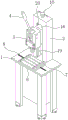
FIG. 1 is a schematic view of the overall structure of the present invention;
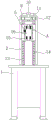
FIG. 2 is a schematic view of the front sectional structure of the adjusting mechanism of the present invention;
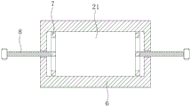
FIG. 3 is a schematic top view of the stamping plate according to the present invention;
fig. 4 is an enlarged schematic view of a point a in fig. 2 according to the present invention.
In the figure: 1. a stamping workbench; 2. a punch press mount; 3. a punch body; 4. punching a spanner; 5. an adjustment mechanism; 6. stamping the plate; 7. a fixed block; 8. a screw; 9. a gear cavity; 10. a rotating wheel; 11. a driving gear; 12. a driven gear; 13. a screw rod groove; 14. a screw rod group; 15. an adjusting block; 16. a linkage block; 17. a convex column; 18. a spring; 19. a chute; 20. a slider; 21. and (4) adjusting the groove.
Detailed Description
The technical solutions in the embodiments of the present invention will be described clearly and completely with reference to the accompanying drawings in the embodiments of the present invention, and it is obvious that the described embodiments are only some embodiments of the present invention, not all embodiments.
To maintain the following description of the embodiments of the present disclosure clear and concise, a detailed description of known functions and known components have been omitted from the present disclosure.
Referring to fig. 1-4, the present invention provides a technical solution: a sand mold manufacturing device for stamping mold casting comprises a stamping workbench 1 and a stamping machine main body 3, wherein a stamping wrench 4 is arranged on the stamping machine main body 3, a stamping machine support 2 is arranged on the stamping workbench 1, an adjusting mechanism 5 is arranged inside the stamping machine support 2, and the stamping machine main body 3 is assembled to move in the vertical direction of the stamping workbench 1 through the adjusting mechanism 5; be provided with punching press board 6 on stamping workpiece 1, the adjustment tank 21 has been seted up on punching press board 6, the activity is provided with fixed block 7 in the adjustment tank 21, the coupling has screw rod 8 on the outer wall of fixed block 7, foretell structural design can be when the moulding-die, make punching machine main part 3 along the vertical direction activity of stamping workpiece 1 through rotating runner 10, the staff of being convenient for carries out the feeding work before the moulding-die and the work of getting behind the moulding-die, can drive the horizontal plane activity of fixed block 7 along punching press board 6 through rotating screw rod 8 simultaneously, the staff of being convenient for fixes sand mould down through fixed block 7, prevent down that the sand mould shifts at the moulding-die in-process.
As shown in fig. 1 and 2, the utility model discloses among the further technical scheme that provides, adjustment mechanism 5 includes runner 10 and driving gear 11, gear chamber 9 has been seted up at punching machine support 2's top, runner 10 activity sets up on the outer wall at punching machine support 2 top, runner 10's axostylus axostyle runs through and the coupling is on the inner wall of gear chamber 9, driving gear 11 fixed mounting is on runner 10 axostylus axostyle is located the outer wall in gear chamber 9, foretell structural design is convenient for the staff and drives driving gear 11 synchronous rotation when rotating runner 10.
Wherein, adjustment mechanism 5 still includes driven gear 12 and lead screw group 14, screw groove 13 has been seted up to the symmetry on the outer wall of punching machine support 2 inboard, the one end coupling of screw group 14 is on the inner wall of screw groove 13, the other end of screw group 14 runs through and the coupling is on the inner wall of gear chamber 9, driven gear 12 fixed mounting is on the outer wall that screw group 14 is located gear chamber 9 to the meshing is connected in driving gear 11, above-mentioned structural design can be when driving gear 11 rotates, 14 rotations of screw group are driven in step through driven gear 12.
Further referring to fig. 2 and 4, it can be seen that, in some embodiments, preferably, the adjusting mechanism 5 further includes an adjusting block 15, a linkage block 16, a protruding column 17 and a spring 18, the adjusting block 15 is fixedly mounted on an adjusting nut of the screw rod set 14, the linkage block 16 is fixedly mounted on an outer wall of the side of the punch main body 3 adjacent to the punch support 2 and is inserted between the two adjusting blocks 15, the protruding columns 17 are respectively fixedly mounted on outer walls of the adjacent sides of the adjusting block 15 and the linkage block 16, and the spring 18 is disposed between the two protruding columns 17, the above structural design is convenient for the adjusting block 15 to drive the linkage block 16 to move upwards synchronously through the spring 18 disposed on the protruding column 17 between the adjusting block 15 and the linkage block 16 when the adjusting block moves, and buffers acting force through deformation of the spring 18 when the die pressing, so as to prevent the acting force from damaging the screw rod set 14.
The utility model discloses among the further technical scheme that provides, adjustment mechanism 5 still includes slider 20, spout 19 has been seted up to the symmetry on the outer wall of punching machine support 2 inboard, slider 20 symmetry is installed in the both sides of linkage piece 16, and plug in spout 19's inside, foretell structural design can be when linkage piece 16 moves about, slider 20 through both sides is at spout 19 internalization to make punching machine main part 3 remain stable, provide the holding power to punching machine main part 3 through slider 20 simultaneously, prevent that the effort from leading to the fact the damage to screw group 14.
The working principle is as follows: when the device is used, as shown in fig. 1-4, when a worker needs to manufacture a sand mold, a lower sand mold is firstly placed under a punch main body 3, then a wrench is used for clockwise rotating a screw 8, the screw 8 is enabled to rotate and drive fixing blocks 7 to move in the direction of the lower sand mold, after the lower sand mold is fixed by the two fixing blocks 7, a rotating wheel 10 can be anticlockwise rotated, driven gears 12 on two sides are synchronously driven to reversely rotate by a driving gear 11 on the rotating wheel 10, a lead screw group 14 connected with the two driven gears 12 can synchronously reversely rotate, an adjusting nut on the lead screw group 14 can synchronously drive an adjusting block 15 to move upwards, a spring 18 arranged on a convex column 17 between the adjusting block 10 and the linkage block 16 drives the linkage block 16 to synchronously move upwards, when the linkage block 16 moves upwards, a sliding block 20 on two sides moves in a sliding chute 19, so that punching machine main part 3 remains stable, move to suitable position back at punching machine main part 3 simultaneously, can be with last sand mould fixed mounting in punching machine main part 3's output, and clockwise rotation runner 10, make punching machine main part 3 drive the sand mould and connect in lower sand mould, can stimulate punching press spanner 4 downwards this moment, in order to carry out moulding-die work to the sand mould, and when moulding-die, provide the holding power to punching machine main part 3 through slider 20, prevent that the effort from causing the damage to lead screw group 14, after the moulding-die finishes, can anticlockwise rotation runner 10, make punching machine main part 3 drive the sand mould and break away from in lower sand mould, the staff of being convenient for gets the material.
The spring 18 mentioned herein has a coefficient of elasticity that meets the technical requirements of the technical solution of the present invention.
The electrical components presented in the document are all electrically connected with an external master controller and 220V mains, and the master controller can be a conventional known device controlled by a computer or the like.
The above embodiments are merely exemplary embodiments of the present invention, which is not intended to limit the present invention, and the scope of the present invention is defined by the appended claims. Various modifications and equivalents may be made by those skilled in the art to the present invention without departing from the spirit and scope of the invention, and such modifications and equivalents should be considered to be within the scope of the invention.
Claims (5)
1. The utility model provides a sand mould making devices is used in punching press type casting, includes stamping workbench (1) and punching machine main part (3), be provided with punching press spanner (4), its characterized in that on punching machine main part (3):
a punch support (2) is arranged on the punching workbench (1), an adjusting mechanism (5) is arranged in the punch support (2), and the punch main body (3) is assembled to move along the vertical direction of the punching workbench (1) through the adjusting mechanism (5);
the stamping device is characterized in that a stamping plate (6) is arranged on the stamping workbench (1), an adjusting groove (21) is formed in the stamping plate (6), a fixing block (7) is movably arranged in the adjusting groove (21), and a screw rod (8) is coupled to the outer wall of the fixing block (7).
2. The sand mold manufacturing apparatus for press casting according to claim 1, characterized in that: adjustment mechanism (5) include runner (10) and driving gear (11), gear chamber (9) have been seted up at the top of punching machine support (2), runner (10) activity set up in on the outer wall at punching machine support (2) top, the axostylus axostyle of runner (10) runs through and the coupling in on the inner wall of gear chamber (9), driving gear (11) fixed mounting in runner (10) axostylus axostyle is located on the outer wall in gear chamber (9).
3. The sand mold manufacturing apparatus for press casting according to claim 2, characterized in that: adjustment mechanism (5) still include driven gear (12) and lead screw group (14), lead screw groove (13) have been seted up to the symmetry on the outer wall of punching machine support (2) inboard, the one end coupling of lead screw group (14) in on the inner wall of lead screw groove (13), the other end of lead screw group (14) runs through and the coupling in on the inner wall of gear chamber (9), driven gear (12) fixed mounting in lead screw group (14) are located on the outer wall in gear chamber (9) to the meshing connect in driving gear (11).
4. The sand mold manufacturing apparatus for press casting according to claim 3, characterized in that: the adjusting mechanism (5) further comprises adjusting blocks (15), linkage blocks (16), convex columns (17) and springs (18), wherein the adjusting blocks (15) are fixedly installed on adjusting nuts of the screw rod group (14), the linkage blocks (16) are fixedly installed on the outer wall of one side, adjacent to the punch support (2), of the punch main body (3) and are inserted between the two adjusting blocks (15), the convex columns (17) are respectively and fixedly installed on the outer walls of the adjacent sides of the adjusting blocks (15) and the linkage blocks (16), and the springs (18) are arranged between the two convex columns (17).
5. The sand mold manufacturing apparatus for press casting according to claim 4, characterized in that: the adjusting mechanism (5) further comprises sliding blocks (20), sliding grooves (19) are symmetrically formed in the outer wall of the inner side of the punch support (2), and the sliding blocks (20) are symmetrically installed on two sides of the linkage block (16) and are inserted into the sliding grooves (19).
Priority Applications (1)
| Application Number | Priority Date | Filing Date | Title |
|---|---|---|---|
| CN202022498828.8U CN213613990U (en) | 2020-11-03 | 2020-11-03 | Sand mold manufacturing device for stamping casting |
Applications Claiming Priority (1)
| Application Number | Priority Date | Filing Date | Title |
|---|---|---|---|
| CN202022498828.8U CN213613990U (en) | 2020-11-03 | 2020-11-03 | Sand mold manufacturing device for stamping casting |
Publications (1)
| Publication Number | Publication Date |
|---|---|
| CN213613990U true CN213613990U (en) | 2021-07-06 |
Family
ID=76628122
Family Applications (1)
| Application Number | Title | Priority Date | Filing Date |
|---|---|---|---|
| CN202022498828.8U Active CN213613990U (en) | 2020-11-03 | 2020-11-03 | Sand mold manufacturing device for stamping casting |
Country Status (1)
| Country | Link |
|---|---|
| CN (1) | CN213613990U (en) |
-
2020
- 2020-11-03 CN CN202022498828.8U patent/CN213613990U/en active Active
Similar Documents
| Publication | Publication Date | Title |
|---|---|---|
| CN213613990U (en) | Sand mold manufacturing device for stamping casting | |
| CN211839855U (en) | Graphite strip bracket shaping shedder | |
| CN214133518U (en) | Press for manufacturing die-casting die | |
| CN218019143U (en) | Extrusion forming die for water permeable brick production | |
| CN111014491B (en) | Card holds in palm punching press and moulds plastics integrated device | |
| CN211221698U (en) | Hot-press forming die for automobile steering wheel | |
| CN114273501A (en) | Multifunctional steel plate stamping die and use method thereof | |
| CN215355957U (en) | Spring processing die | |
| CN209969374U (en) | Automatic blanking hardware mould | |
| CN111687263A (en) | Anti-deformation aluminum barrel wall body forming device | |
| CN211139394U (en) | Auxiliary mounting device for automobile cup stand panel die | |
| CN220311581U (en) | Improved generation power box mould | |
| CN104249097A (en) | Numerical control flexible roll bending fully-automatic plate bending machine special for miniature motor enclosure | |
| CN220837550U (en) | Relay reed stamping die | |
| CN213378939U (en) | Sheet metal machining device capable of automatically ejecting sheet metal part | |
| CN212329328U (en) | Full-automatic numerical control bender positioner | |
| CN214927325U (en) | Artwork compression molding device | |
| CN215143935U (en) | Mould embryo performing device of complicated precision mould | |
| CN217798339U (en) | Multi-angle composite stamping device | |
| CN211729613U (en) | Direct-pressing forming press for bathroom ceramic blanks | |
| CN217223250U (en) | Quick setting mechanism of electronic product casing production | |
| CN211676267U (en) | Filling machine for toy production | |
| CN220837263U (en) | Steel extrusion molding device with positioning function | |
| CN219561114U (en) | Forming die for aluminum product manufacturing | |
| CN213613721U (en) | Stamping die frame structure |
Legal Events
| Date | Code | Title | Description |
|---|---|---|---|
| GR01 | Patent grant | ||
| GR01 | Patent grant |