CN213586120U - Control box for communication base station - Google Patents
Control box for communication base station Download PDFInfo
- Publication number
- CN213586120U CN213586120U CN202121185896.7U CN202121185896U CN213586120U CN 213586120 U CN213586120 U CN 213586120U CN 202121185896 U CN202121185896 U CN 202121185896U CN 213586120 U CN213586120 U CN 213586120U
- Authority
- CN
- China
- Prior art keywords
- control box
- sound
- layer
- base station
- communication base
- Prior art date
- Legal status (The legal status is an assumption and is not a legal conclusion. Google has not performed a legal analysis and makes no representation as to the accuracy of the status listed.)
- Active
Links
Images


Abstract
The utility model provides a control box for a communication base station, which comprises a supporting rod, wherein the supporting rod is provided with a control box, the inner peripheral wall of the control box is provided with a sound insulation board, the rear side of the control box is provided with an insulating panel, and the insulating panel is provided with two groups of heat dissipation mechanisms; the heat dissipation mechanism includes the sound absorbing cover, and the heat conduction copper is installed to the rear end opening part of sound absorbing cover, and the inboard of sound absorbing cover has three installation cavity through inhaling the sound baffle branch, and the fan is all installed to the inboard of installation cavity, and the fan passes through bolt and heat conduction copper fixed connection, and four apex angle departments in the fan outside install damper one by one. The utility model discloses the volume is less, and portable can satisfy the practical application demand.
Description
Technical Field
The utility model relates to a communication equipment technical field, in particular to a control box for communication base station.
Background
In the field of communicating information, communication base stations are very important devices. Specifically, a communication base station is an interface device for a mobile device to access the internet, and is a form of a radio station, which refers to a radio transceiver station for information transmission between a mobile telephone terminal and a mobile communication switching center in a certain radio coverage area.
The prior patent (application number: 201922264942.1) provides an environment-friendly information communication base station, which comprises a tower frame, wherein a control box is fixedly connected to the tower frame, a first fixing plate is fixedly mounted at the top of the control box, two fixing seats are fixedly mounted at the top of the first fixing plate, fixing cavities are formed in the two fixing seats, rotating holes are formed in the inner walls of the tops of the two fixing cavities, rotating columns are rotatably mounted in the two rotating holes, a solar panel is fixedly connected to the top ends of the two rotating columns, and first gears are fixedly mounted at the bottom ends of the two rotating columns.
However, the communication base station is too bulky to be applied to a mobile scene; in addition, because the communication equipment is not internally provided with protective measures, components in the communication equipment are easy to corrode, and the normal service life is influenced.
SUMMERY OF THE UTILITY MODEL
Based on this, the present invention provides a control box for a communication base station for solving the technical problems in the background art.
The utility model provides a control box for communication base station, including the bracing piece, be equipped with the control box on the bracing piece, install the acoustic celotex board on the internal perisporium of control box, the rear side of control box is installed insulating panel, install two sets of heat dissipation mechanisms on the insulating panel;
each group of heat dissipation mechanisms comprises a sound absorption cover which is a rectangular box structure with two uncovered ends, a heat conduction copper plate is installed at an opening at the rear end of the sound absorption cover, the inner side of the sound absorption cover is divided into three installation chambers through sound absorption partition plates, a fan is installed on the inner side of each installation chamber, the fan is fixedly connected with the heat conduction copper plate through bolts, and damping assemblies are installed at four vertex angles on the outer side of the fan one by one;
every damping component includes the rubber column, the one end of rubber column with the surface connection of heat conduction copper, the other end links to each other with the inner wall of sound absorbing cover, the periphery cover of rubber column is equipped with the spring.
Further, the inside and outside of sound absorbing cover is respectively for inhaling sound glue film and metal level, it is equipped with porous sound absorbing layer and puigging in proper order to inhale the one side that the sound glue film is close to the metal level.
Further, air pipe is all installed to the symmetry on the both sides wall of control box, air pipe with the control box link up mutually, be connected with the switching pipe through threaded engagement on air pipe's the one end inner wall, install the filter screen on the other end inner wall.
Furthermore, a first water absorption screen plate and a second water absorption screen plate are installed on the inner side of the adapter tube, a plurality of water absorption resin balls are arranged between the first water absorption screen plate and the second water absorption screen plate, and the diameter of each water absorption resin ball is larger than the aperture of each first water absorption screen plate and the aperture of each second water absorption screen plate.
Further, the sound insulation layer is a polyurethane foam layer, and the sound insulation layer is bonded with the metal layer through gluing.
Further, the porous sound absorption layer is a wave sponge layer, and the inner side and the outer side of the porous sound absorption layer are respectively bonded and connected with the sound absorption glue layer and the sound insulation layer through gluing.
Further, the upper end and the lower end of the heat-conducting copper plate are symmetrically provided with fixing plates, and fixing through holes are formed in the fixing plates.
Furthermore, an access door is installed at the opening at the front end of the control box, and a door lock is arranged on the access door.
Compared with the prior art, the beneficial effects of the utility model are that:
the utility model provides a control box for communication base station, the volume is less, is convenient for actually carry and remove, can be applicable to various specific occasions that need to remove, has improved the convenience of practical application, has satisfied practical application demand;
in addition, through arranging the ventilating duct, the ventilation can be realized, and rainwater can be effectively prevented from entering the control box in rainy days so as to protect communication equipment in the control box;
on the other hand, owing to set up first otter board, the resin ball that absorbs water and the otter board that absorbs water of second in the adapter tube, under the condition that realizes ventilation cooling, can guarantee the inside drying of control box, avoid causing the inside components and parts of control box to take place the corrosion because of the humidity and lead to influencing life.
Additional features and advantages of the disclosure will be set forth in the description which follows, or in part may be learned by the practice of the above-described techniques of the disclosure, or may be learned by practice of the disclosure.
In order to make the aforementioned and other objects, features and advantages of the present invention comprehensible, preferred embodiments accompanied with figures are described in detail below.
Drawings
Fig. 1 is a schematic diagram of an overall structure of a control box for a communication base station according to the present invention;
fig. 2 is a cross-sectional view of the internal structure of a control box in a control box for a communication base station according to the present invention;
fig. 3 is a schematic structural diagram of a heat dissipation mechanism in a control box for a communication base station according to the present invention;
fig. 4 is a structural cross-sectional view of a sound absorbing cover in a control box for a communication base station according to the present invention;
fig. 5 is a cross-sectional view of the structure of the adapter tube in the control box for the communication base station according to the present invention;
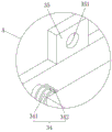
fig. 6 is an enlarged view of a structure at a in fig. 3.
Description of the main symbols:
1. a support bar; 2. a control box; 21. an insulating panel; 22. a ventilation duct; 23. an access door; 24. a filter screen; 25. a sound insulating board; 3. a heat dissipation mechanism; 31. a sound absorbing cover; 311. a sound absorption glue layer; 312. a metal layer; 313. a porous sound absorbing layer; 314. a sound insulating layer; 32. a sound-absorbing partition plate; 33. a fan; 34. a shock absorbing assembly; 341. a rubber column; 342. a spring; 35. a fixing plate; 351. a fixing through hole; 36. a heat-conducting copper plate; 4. a transfer tube; 41. a first water absorbent mesh sheet; 42. a second water absorbent mesh sheet; 43. a water-absorbent resin ball.
Detailed Description
In order to facilitate understanding of the present invention, the present invention will be described more fully hereinafter with reference to the accompanying drawings. Preferred embodiments of the present invention are shown in the drawings. The invention may, however, be embodied in many different forms and should not be construed as limited to the embodiments set forth herein. Rather, these embodiments are provided so that this disclosure will be thorough and complete.
Unless defined otherwise, all technical and scientific terms used herein have the same meaning as commonly understood by one of ordinary skill in the art to which this invention belongs. The terminology used in the description of the invention herein is for the purpose of describing particular embodiments only and is not intended to be limiting of the invention. As used herein, the term "and/or" includes any and all combinations of one or more of the associated listed items.
Referring to fig. 1 to 6, the present invention provides a control box for a communication base station, which includes a support rod 1.
The support rod 1 is provided with a control box 2, and the inner peripheral wall of the control box 2 is provided with a sound insulation board 25. In the present embodiment, the sound insulation board 25 and the sound absorption partition board 32 are both made of polyester fiber material, and have the functions of sound insulation, flame retardance and moisture resistance.
An insulating panel 21 is mounted on the rear side of the control box 2, and two sets of heat dissipation mechanisms 3 are mounted on the insulating panel 21. Specifically, the method comprises the following steps. Each group of heat dissipation mechanisms 3 comprises a sound absorption cover 31, and the sound absorption cover 31 is a rectangular box structure with two uncovered ends. Further, a heat conductive copper plate 36 is attached to the rear end opening of the sound absorbing cover 31. It can be understood that the heat conduction can be accelerated by the heat conducting copper plate 36, and the heat generated by the communication equipment during operation can be quickly dissipated into the air by the fan 33, so that the heat dissipation effect is improved.
Meanwhile, the inside of the sound-absorbing cover 31 is divided into three mounting chambers by the sound-absorbing partition plates 32. A fan 33 is installed on the inner side of each installation chamber, and the fan 33 is fixedly connected with the heat-conducting copper plate 36 through bolts. Further, damper assemblies 34 are mounted one by one at four top corners of the outside of the fan 33.
Specifically, each damping member 34 includes a rubber column 341, one end of the rubber column 341 is connected to the surface of the heat-conducting copper plate 36, the other end is connected to the inner wall of the sound-absorbing cover 31, and a spring 342 is fitted around the rubber column 341. In this embodiment, the rubber column 341 is made of heat-resistant rubber, and the vibration generated during the operation of the fan 33 can be buffered and absorbed by the rubber column 341 and the spring 342, so that the noise caused by the vibration can be reduced, and the noise reduction effect can be greatly improved.
In this embodiment, the sound absorbing cover 31 includes a sound absorbing adhesive layer 311 and a metal layer 312 on the inner and outer sides thereof. The metal layer 312 may be made of a metal material such as aluminum. Further, a porous sound absorbing layer 313 and a sound insulating layer 314 are provided in this order on the side of the sound absorbing adhesive layer 311 close to the metal layer 312. Here, the sound absorbing rubber layer 311 is made of a rubber polymer material. The fan 33 has a sound insulation function, and can buffer and absorb vibration generated when the fan 33 works, so that noise is reduced.
In this embodiment, the sound insulation layer 314 is a polyurethane foam layer. Wherein the sound insulation layer 314 is adhesively connected to the metal layer 312 by gluing. The soundproof layer 314 is made of a polyurethane foam material, and has a good sound absorption effect. In addition, the porous sound absorbing layer 313 is a wave sponge layer, and the inner side and the outer side of the porous sound absorbing layer 313 are respectively bonded and connected with the sound absorbing glue layer 311 and the sound insulating layer 314 through gluing. In this embodiment, the porous sound absorbing layer 313 is made of a wave sponge, and this arrangement can effectively reduce the noise generated when the fan 33 operates.
The fixing plates 35 are symmetrically mounted on the upper and lower ends of the heat-conducting copper plate 36, and the fixing plates 35 are provided with fixing through holes 351. It can be understood that the fixing through hole 351 is screwed with a matching bolt, and the heat dissipation mechanism 3 can be mounted and dismounted by using the bolt.
An access door 23 is installed at an opening at the front end of the control box 2, and in actual operation, communication equipment and circuits in the control box 2 can be overhauled by opening the access door 23. Further, a door lock is provided on the access door 23. It will be appreciated that the provision of a door lock may improve the security of the base station.
Further, ventilation ducts 22 are symmetrically mounted on both side walls of the control box 2. It can be understood that the ventilation duct 22 not only can realize ventilation and accelerate heat dissipation, but also can effectively prevent rainwater from entering the control box 2 in rainy days so as to protect the communication equipment in the control box 2.
In the present embodiment, the ventilation duct 22 communicates with the control box 2. The inner wall of one end of the ventilation pipeline 22 is connected with a switching pipe 4 through thread engagement, the outer wall of the switching pipe 4 is provided with external threads, and the inner wall of one end of the ventilation pipeline 22 is provided with internal threads. It can be understood that the adapter tube 4 can be mounted and dismounted by the mutual engagement between the internal thread and the external thread. Further, a filter screen 24 is attached to the inner wall of the other end of the ventilation duct 22. It can be understood that the filter screen 24 can effectively prevent external dust, leaves and the like from entering the control box 2, and the dustproof effect is good.
In order to ensure the drying inside the control box 2, a first water absorbing screen plate 41 and a second water absorbing screen plate 42 are installed on the inner side of the adapter tube 4. In this embodiment, the first water absorbing screen 41 and the second water absorbing screen 42 are both made of water absorbing material such as absorbent cotton, and thus have good water absorption. Further, a plurality of water absorbent resin balls 43 are provided between the first water absorbent mesh plate 41 and the second water absorbent mesh plate 42.
In this embodiment, the diameter of the water absorbent resin ball 43 is larger than the aperture of the first water absorbent mesh plate 41 and the second water absorbent mesh plate 42. Wherein, the resin ball 43 that absorbs water adopts super absorbent resin to make, can effectively adsorb the moisture in the outside air to guarantee the inside drying of control box 2.
The utility model discloses a concrete operation as follows:
the utility model provides a control box for communication base station, the volume is less, is convenient for actually carry and remove, can be applicable to various specific occasions that need to remove, has improved the convenience of practical application, has satisfied practical application demand;
the heat conduction copper plate 36 can accelerate heat conduction, the fan 33 can be used for dissipating heat generated by the communication equipment during working into the air, and the ventilation and the air permeation are realized through the arranged ventilation pipeline 22 to accelerate heat dissipation; during the operation of the fan 33, the rubber column 341 and the spring 342 are arranged to absorb and buffer the vibration generated during the operation of the fan 33, so as to reduce the noise caused by the vibration; then, the sound absorption glue layer 311 absorbs the reflected partial sound, the sound absorption glue layer 311 can buffer and absorb the vibration generated when the fan 33 works, the noise is further reduced, then the sound is transmitted to the porous sound absorption layer 313 and the sound insulation layer 314, the reflected partial sound is further absorbed by the porous sound absorption layer 313 and the sound insulation layer 314, and then the residual noise is absorbed by the sound insulation board 25 and the sound absorption partition board 32, so that a good noise reduction effect is realized;
by arranging the ventilating duct 22, not only can ventilation be realized, but also rainwater can be effectively prevented from entering the control box 2 in rainy days, so that communication equipment in the control box 2 is protected; on the other hand, because set up first otter board 41 that absorbs water, resin ball 43 and the second otter board 42 that absorbs water in adapter tube 4, under the condition that realizes ventilation cooling, can guarantee the inside drying of control box 2, avoid causing the inside components and parts of control box to take place the corrosion because of the humidity and lead to the fact life.
Finally, it should be noted that: the above-mentioned embodiments are only specific embodiments of the present invention, and are not intended to limit the technical solution of the present invention, and the protection scope of the present invention is not limited thereto, although the present invention is described in detail with reference to the foregoing embodiments, those skilled in the art should understand that: those skilled in the art can still modify or easily conceive of changes in the technical solutions described in the foregoing embodiments or make equivalent substitutions for some technical features within the technical scope of the present disclosure; such modifications, changes or substitutions do not substantially depart from the spirit and scope of the embodiments of the present invention, and are intended to be included within the scope of the present invention. Therefore, the protection scope of the present invention shall be subject to the protection scope of the claims.
Claims (8)
1. A control box for a communication base station comprises a support rod (1) and is characterized in that the support rod (1) is provided with a control box (2), the inner peripheral wall of the control box (2) is provided with a sound insulation board (25), the rear side of the control box (2) is provided with an insulating panel (21), and the insulating panel (21) is provided with two groups of heat dissipation mechanisms (3);
each group of heat dissipation mechanisms (3) comprises a sound absorption cover (31), the sound absorption cover (31) is of a rectangular box structure with two uncovered ends, a heat conduction copper plate (36) is installed at an opening at the rear end of the sound absorption cover (31), the inner side of the sound absorption cover (31) is divided into three installation cavities through a sound absorption partition plate (32), a fan (33) is installed on the inner side of each installation cavity, the fan (33) is fixedly connected with the heat conduction copper plate (36) through bolts, and four vertex angles of the outer side of the fan (33) are respectively provided with a damping component (34);
each damping component (34) comprises a rubber column (341), one end of the rubber column (341) is connected with the surface of the heat-conducting copper plate (36), the other end of the rubber column is connected with the inner wall of the sound absorption cover (31), and a spring (342) is sleeved on the periphery of the rubber column (341).
2. The control box of claim 1, wherein the sound-absorbing cover (31) has a sound-absorbing glue layer (311) and a metal layer (312) on the inner and outer sides, and a porous sound-absorbing layer (313) and a sound-insulating layer (314) are sequentially disposed on the side of the sound-absorbing glue layer (311) close to the metal layer (312).
3. The control box for the communication base station according to claim 2, wherein the two side walls of the control box (2) are symmetrically provided with ventilation pipelines (22), the ventilation pipelines (22) are communicated with the control box (2), the inner wall of one end of each ventilation pipeline (22) is connected with a switching pipe (4) through threaded engagement, and the inner wall of the other end of each ventilation pipeline is provided with a filter screen (24).
4. The control box for the communication base station according to claim 3, wherein a first water absorption screen plate (41) and a second water absorption screen plate (42) are installed on the inner side of the adapter tube (4), a plurality of water absorption resin balls (43) are arranged between the first water absorption screen plate (41) and the second water absorption screen plate (42), and the diameter of each water absorption resin ball (43) is larger than the aperture of each first water absorption screen plate (41) and the aperture of each second water absorption screen plate (42).
5. A control box for a communication base station according to claim 2, characterized in that the sound-insulating layer (314) is a polyurethane foam layer, and the sound-insulating layer (314) is adhesively connected to the metal layer (312) by gluing.
6. The control box for the communication base station according to claim 2, wherein the porous sound absorption layer (313) is a wave sponge layer, and the inner side and the outer side of the porous sound absorption layer (313) are respectively bonded with the sound absorption glue layer (311) and the sound insulation layer (314) by gluing.
7. The control box for the communication base station as claimed in claim 2, wherein the upper and lower ends of the heat-conducting copper plate (36) are symmetrically provided with fixing plates (35), and the fixing plates (35) are provided with fixing through holes (351).
8. The control box for the communication base station according to claim 2, characterized in that an access door (23) is installed at the opening of the front end of the control box (2), and a door lock is arranged on the access door (23).
Priority Applications (1)
| Application Number | Priority Date | Filing Date | Title |
|---|---|---|---|
| CN202121185896.7U CN213586120U (en) | 2021-05-31 | 2021-05-31 | Control box for communication base station |
Applications Claiming Priority (1)
| Application Number | Priority Date | Filing Date | Title |
|---|---|---|---|
| CN202121185896.7U CN213586120U (en) | 2021-05-31 | 2021-05-31 | Control box for communication base station |
Publications (1)
| Publication Number | Publication Date |
|---|---|
| CN213586120U true CN213586120U (en) | 2021-06-29 |
Family
ID=76553313
Family Applications (1)
| Application Number | Title | Priority Date | Filing Date |
|---|---|---|---|
| CN202121185896.7U Active CN213586120U (en) | 2021-05-31 | 2021-05-31 | Control box for communication base station |
Country Status (1)
| Country | Link |
|---|---|
| CN (1) | CN213586120U (en) |
-
2021
- 2021-05-31 CN CN202121185896.7U patent/CN213586120U/en active Active
Similar Documents
| Publication | Publication Date | Title |
|---|---|---|
| CN211139043U (en) | Battery installation box for new energy automobile | |
| CN211290316U (en) | Anti-falling protection device for outdoor unit of air conditioner | |
| CN213586120U (en) | Control box for communication base station | |
| CN111456850A (en) | Power supply sound insulation device of diesel generator | |
| CN211720408U (en) | Special low noise motor device of outdoor cooling tower | |
| CN212485086U (en) | Noise-reducing and shock-absorbing dry-type transformer | |
| CN210694637U (en) | Electromechanical protection device | |
| CN111907348A (en) | Battery fixing structure with shock attenuation effect for new energy automobile | |
| CN217406020U (en) | Prepackage type power distribution station with amortization structure | |
| CN213362811U (en) | Air conditioner shell structure with sound insulation function | |
| CN214753231U (en) | Transformer with shock resistance function | |
| CN215765462U (en) | Noise reduction device suitable for air conditioner outdoor unit | |
| CN206259614U (en) | A kind of power equipment noise reduction buffer device | |
| CN213520954U (en) | Electric installation cabinet that radiating effect is good | |
| CN212677542U (en) | Energy-saving monitoring cabinet with bidirectional heat dissipation function | |
| CN213007562U (en) | Adjustable extended range type vehicle type cooling module | |
| CN211421952U (en) | Noise reduction device for fan room | |
| CN220855600U (en) | Computer mainframe box with shock attenuation noise reduction function | |
| CN110932105A (en) | Box-type substation noise elimination shell structure | |
| CN211182816U (en) | Box-type substation noise elimination shell structure | |
| CN218730349U (en) | Inductor with anticorrosion function | |
| CN216278603U (en) | Low noise roof ventilator | |
| CN219394577U (en) | Motor shell structure | |
| CN215819148U (en) | Electronic engineering is with safe type switch board | |
| CN207321730U (en) | A kind of power amplifier of train broadcast transmitter |
Legal Events
| Date | Code | Title | Description |
|---|---|---|---|
| GR01 | Patent grant | ||
| GR01 | Patent grant |