CN213530712U - Sport equipment belt pulley die casting die - Google Patents
Sport equipment belt pulley die casting die Download PDFInfo
- Publication number
- CN213530712U CN213530712U CN202022087766.1U CN202022087766U CN213530712U CN 213530712 U CN213530712 U CN 213530712U CN 202022087766 U CN202022087766 U CN 202022087766U CN 213530712 U CN213530712 U CN 213530712U
- Authority
- CN
- China
- Prior art keywords
- die
- plate
- assembly
- movable
- fixed
- Prior art date
- Legal status (The legal status is an assumption and is not a legal conclusion. Google has not performed a legal analysis and makes no representation as to the accuracy of the status listed.)
- Expired - Fee Related
Links
Images

Abstract
The utility model provides a sport equipment belt pulley die casting die, include: the die comprises a die body, a fixed die assembly, a movable die assembly, an ejection assembly, a guide assembly and a die casting; the appearance of the die body is in a cuboid structure, and the die body is provided with a fixed die assembly, a movable die assembly, an ejection assembly and a guide assembly; the die casting is formed between the fixed die assembly and the movable die assembly; a top plate is arranged at the top of the fixed die assembly; a fixed template is arranged on the lower side of the top plate and is connected with the top plate through bolts; a fixed die insert is arranged in the fixed die plate and connected with the fixed die plate through a bolt; a positioning ring is arranged above the top plate; the utility model discloses a to the improvement of a sport equipment belt pulley die casting die, it is reasonable to have a structural design, makes things convenient for the side shaping of belt pulley die casting, makes things convenient for ejecting advantage to effectual problem and the not enough that has solved current device and appear.
Description
Technical Field
The utility model relates to a die casting die technical field, more specifically the theory that says so especially relates to a sport equipment belt pulley die casting die.
Background
The die casting process is a process completed on a special die casting machine. Molten metal is cast at low speed or high speed and filled into the cavity of the mold, the mold has movable cavity surface, and it is pressurized and forged along with the cooling process of the molten metal, so that the shrinkage cavity and shrinkage porosity defects of the blank are eliminated, and the internal structure of the blank reaches the broken crystal grains in the forged state. The belt pulley belongs to a hub part, the manufacturing process generally mainly comprises casting and forging, and when the belt pulley is manufactured by using a die-casting process, the side surface of the belt pulley is not easy to form and is inconvenient to demould.
In view of this, research improvement is carried out to current problem, provides a sport equipment belt pulley die casting die, has structural design rationally, makes things convenient for the side shaping of belt pulley die casting, makes things convenient for ejecting advantage, aims at through this technique, reaches the purpose of problem-solving and improvement practical value nature.
SUMMERY OF THE UTILITY MODEL
An object of the utility model is to provide a sport equipment belt pulley die casting die to solve the problem that proposes in the above-mentioned background art and not enough.
In order to achieve the above object, the utility model provides a sport equipment belt pulley die casting die reaches by following specific technical means:
a sports equipment pulley die casting mold, comprising: the die comprises a die body, a fixed die assembly, a movable die assembly, an ejection assembly, a guide assembly, a die casting piece, a top plate, a fixed die insert, a positioning ring, a sprue bush, a pouring channel, an inclined guide post, a movable die plate, a movable die insert, a sliding block, a bottom plate, square iron, a lower base plate, an upper base plate, a push rod, a reset rod, a guide sleeve and a guide post; the appearance of the die body is in a cuboid structure, and the die body is provided with a fixed die assembly, a movable die assembly, an ejection assembly and a guide assembly; the die casting is formed between the fixed die assembly and the movable die assembly; a top plate is arranged at the top of the fixed die assembly; a fixed template is arranged on the lower side of the top plate and is connected with the top plate through bolts; a fixed die insert is arranged in the fixed die plate and connected with the fixed die plate through a bolt; a positioning ring is arranged above the top plate and is connected with the top plate through a bolt; a sprue bush is arranged in the middle of the fixed template, and the sprue bush and the fixed template are in interference fit; a pouring gate is arranged below the sprue bush; the fixed die plate is provided with an inclined guide pillar, and the inclined guide pillar is in interference fit with the fixed die plate; a movable template is arranged on the movable mold component; the movable die plate is provided with a movable die insert, and the movable die insert is connected with the movable die plate through a bolt; the movable template is provided with a sliding block; a bottom plate is arranged at the bottom of the movable mold component; a square iron is arranged above the bottom plate, and the square iron is connected with the bottom plate through a bolt; a lower base plate is arranged at the bottom of the ejection assembly; an upper base plate is arranged above the lower base plate, and the upper base plate is connected with the lower base plate through bolts; the upper backing plate is provided with a top rod and a reset rod which are in interference fit with the upper backing plate; the fixed die assembly is connected with the movable die assembly through the guide sleeve and the guide pillar.
As a further optimization of this technical scheme, the utility model relates to a sport equipment belt pulley die casting die the side shape shaping of die casting is provided with two oblique guide pillar holes on the slider of two symmetries on and every slider, and oblique guide pillar hole cooperatees with oblique guide pillar.
As a further optimization of this technical scheme, the utility model relates to a sport equipment belt pulley die casting die the downside annular array of die casting is provided with a plurality of ejector pins, and the below of watering is provided with the ejector pin.
As the further optimization of this technical scheme, the utility model relates to a sport equipment belt pulley die casting die all be provided with the guide pin bushing on the four corners of fixed die plate, and the guide pin bushing is interference fit with the fixed die plate.
As a further optimization of this technical scheme, the utility model relates to a sport equipment belt pulley die casting die all be provided with the guide pillar on the four corners of movable mould board, and the guide pillar is interference fit with the movable mould board to the guide pillar is corresponding with the position of guide pin bushing.
Because of above-mentioned technical scheme's application, compared with the prior art, the utility model have the following advantage:
1. the utility model discloses a side shape shaping of die casting is on the slider of two symmetries, and is provided with two oblique guide pillar holes on every slider, and the oblique guide pillar hole cooperatees with oblique guide pillar, the side shaping of the belt pulley die casting of being convenient for.
2. The utility model discloses a downside annular array of die casting is provided with a plurality of ejector pins, and the below of watering is provided with the ejector pin, is convenient for ejecting the die casting.
3. The utility model discloses a to the improvement of a sport equipment belt pulley die casting die, it is reasonable to have a structural design, makes things convenient for the side shaping of belt pulley die casting, makes things convenient for ejecting advantage, thereby effectual solution the utility model discloses the problem that proposes in background art one with not enough.
Drawings
The accompanying drawings, which are incorporated in and constitute a part of this application, are included to provide a further understanding of the invention, and are incorporated in and constitute a part of this specification. In the drawings:
fig. 1 is a schematic structural view of the present invention;
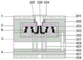
FIG. 2 is a schematic side sectional view of the present invention;
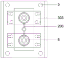
fig. 3 is a schematic top view of the present invention.
In the figure: the die comprises a die body 1, a fixed die component 2, a movable die component 3, an ejection component 4, a guide component 5, a die casting 6, a top plate 201, a fixed die plate 202, a fixed die insert 203, a positioning ring 204, a sprue bush 205, a pouring gate 206, an inclined guide post 207, a movable die plate 301, a movable die insert 302, a slide block 303, a bottom plate 304, square iron 305, a lower backing plate 401, an upper backing plate 402, a top rod 403, a reset rod 404, a guide sleeve 501 and a guide post 502.
Detailed Description
The technical solutions in the embodiments of the present invention will be described clearly and completely with reference to the accompanying drawings in the embodiments of the present invention, and it is obvious that the described embodiments are only some embodiments of the present invention, not all embodiments.
It is to be noted that, in the description of the present invention, "a plurality" means two or more unless otherwise specified; the terms "upper", "lower", "left", "right", "inner", "outer", "front", "rear", "head", "tail", and the like indicate orientations or positional relationships based on the orientations or positional relationships shown in the drawings, and are merely for convenience of description and simplicity of description, and do not indicate or imply that the device or element being referred to must have a particular orientation, be constructed and operated in a particular orientation, and thus, should not be construed as limiting the present invention.
Furthermore, the terms "first," "second," "third," and the like are used for descriptive purposes only and are not to be construed as indicating or implying relative importance.
Meanwhile, in the description of the present invention, unless otherwise explicitly specified or limited, the terms "connected" and "connected" should be interpreted broadly, and may be, for example, fixedly connected, detachably connected, or integrally connected; the connection can be mechanical connection or electrical connection; may be directly connected or indirectly connected through an intermediate. The specific meaning of the above terms in the present invention can be understood in specific cases to those skilled in the art.
Referring to fig. 1 to 3, the present invention provides a specific technical embodiment of a die-casting mold for a belt pulley of a sports apparatus:
a sports equipment pulley die casting mold, comprising: the die comprises a die body 1, a fixed die component 2, a movable die component 3, an ejection component 4, a guide component 5, a die casting 6, a top plate 201, a fixed die plate 202, a fixed die insert 203, a positioning ring 204, a sprue bush 205, a pouring gate 206, an inclined guide post 207, a movable die plate 301, a movable die insert 302, a slide block 303, a bottom plate 304, square iron 305, a lower backing plate 401, an upper backing plate 402, a top rod 403, a reset rod 404, a guide sleeve 501 and a guide post 502; the appearance characteristic of the die body 1 is a cuboid structure, and the die body 1 is provided with a fixed die component 2, a movable die component 3, an ejection component 4 and a guide component 5; the die casting 6 is formed between the fixed die assembly 2 and the movable die assembly 3; the top of the fixed die component 2 is provided with a top plate 201; a fixed template 202 is arranged on the lower side of the top plate 201, and the fixed template 202 is connected with the top plate 201 through bolts; a fixed die insert 203 is arranged in the fixed die plate 202, and the fixed die insert 203 is connected with the fixed die plate 202 through bolts; a positioning ring 204 is arranged above the top plate 201, and the positioning ring 204 is connected with the top plate 201 through bolts; a sprue bush 205 is arranged in the middle of the fixed die plate 202, and the sprue bush 205 is in interference fit with the fixed die plate 202; a pouring channel 206 is arranged below the sprue bush 205; an inclined guide post 207 is arranged on the fixed die plate 202, and the inclined guide post 207 is in interference fit with the fixed die plate 202; a movable template 301 is arranged on the movable mold component 3; a movable die insert 302 is arranged on the movable die plate 301, and the movable die insert 302 is connected with the movable die plate 301 through bolts; the movable template 301 is provided with a slide block 303; the bottom of the movable mold component 3 is provided with a bottom plate 304; a square iron 305 is arranged above the bottom plate 304, and the square iron 305 is connected with the bottom plate 304 through bolts; the bottom of the ejection assembly 4 is provided with a lower backing plate 401; an upper cushion plate 402 is arranged above the lower cushion plate 401, and the upper cushion plate 402 is connected with the lower cushion plate 401 through bolts; the upper backing plate 402 is provided with a push rod 403 and a reset rod 404, and the push rod 403 and the reset rod 404 are in interference fit with the upper backing plate 402; the fixed die assembly 2 and the movable die assembly 3 are connected through a guide sleeve 501 and a guide pillar 502.
Specifically, as shown in fig. 1 and fig. 3, the die casting 6 is formed on two symmetrical sliding blocks 303 in a side shape, and each sliding block is provided with two inclined guide post holes, and the inclined guide post holes are matched with the inclined guide posts 207, so that the belt pulley die casting can be conveniently formed on the side surface.
Specifically, as shown in fig. 1 and 2, a plurality of ejector rods 403 are arranged in an annular array on the lower side of the die casting 6, and the ejector rods 403 are arranged below the pouring gate 206, so that the die casting 6 can be ejected conveniently.
Specifically, as shown in fig. 1, guide sleeves 501 are disposed at four corners of the fixed die plate 202, and the guide sleeves 501 are in interference fit with the fixed die plate 202, so that a guiding effect is achieved during die assembly.
Specifically, as shown in fig. 1, guide posts 502 are disposed at four corners of the movable die plate 301, the guide posts 502 are in interference fit with the movable die plate 301, and the guide posts 502 correspond to the guide sleeves 501 in position, so that a guiding effect is achieved during die assembly.
The method comprises the following specific implementation steps:
when the sports equipment belt pulley die-casting die is used, the die body 1 is arranged on the die-casting machine, the die-casting machine is operated, molten metal enters the die body 1 through the sprue bush 205 and the pouring channel 206, after cooling for a certain time, the die opening button is started, the fixed die component 2 is separated from the movable die component 3, during the mold opening process, the slide block 303 slides outwards under the action of the inclined guide post 207, the formed die casting 6 is ejected under the action of the ejector rod 403, under the action of the spring on the reset rod 404, the ejection assembly 4 is reset, the mold closing button is started, and during mold closing, the slide block 303 slides inward under the action of the angle guide post 207, starting the next molding cycle, this sport equipment belt pulley die casting die has structural design rationally, makes things convenient for the side shaping of belt pulley die casting, and convenient ejecting advantage has satisfied the shaping requirement of belt pulley.
In summary, the following steps: the die-casting die for the belt pulley of the sports equipment is formed on two symmetrical slide blocks through the shape of the side surface of a die-casting piece, and each slide block is provided with two inclined guide post holes which are matched with the inclined guide posts, so that the side surface of the belt pulley die-casting piece is conveniently formed; a plurality of ejector rods are arranged on the lower side of the die casting in an annular array mode, and the ejector rods are arranged below the pouring gate, so that the die casting can be ejected out conveniently; through the improvement to a sport equipment belt pulley die casting die, it is reasonable to have structural design, makes things convenient for the side shaping of belt pulley die casting, makes things convenient for ejecting advantage, thereby effectual solution the utility model discloses the problem that proposes in background art one with not enough.
Although embodiments of the present invention have been shown and described, it will be appreciated by those skilled in the art that changes, modifications, substitutions and alterations can be made in these embodiments without departing from the principles and spirit of the invention, the scope of which is defined in the appended claims and their equivalents.
Claims (5)
1. A sports equipment pulley die casting mold, comprising: the die comprises a die body (1), a fixed die assembly (2), a movable die assembly (3), an ejection assembly (4), a guide assembly (5), a die casting (6), a top plate (201), a fixed die plate (202), a fixed die insert (203), a positioning ring (204), a sprue bush (205), a pouring gate (206), an inclined guide post (207), a movable die plate (301), a movable die insert (302), a sliding block (303), a bottom plate (304), square iron (305), a lower backing plate (401), an upper backing plate (402), a push rod (403), a reset rod (404), a guide sleeve (501) and a guide post (502); the method is characterized in that: the appearance of the die body (1) is of a rectangular structure, and the die body (1) is provided with a fixed die assembly (2), a movable die assembly (3), an ejection assembly (4) and a guide assembly (5); the die casting (6) is formed between the fixed die assembly (2) and the movable die assembly (3); a top plate (201) is arranged at the top of the fixed die assembly (2); a fixed template (202) is arranged on the lower side of the top plate (201), and the fixed template (202) is connected with the top plate (201) through bolts; a fixed die insert (203) is arranged in the fixed die plate (202), and the fixed die insert (203) is connected with the fixed die plate (202) through bolts; a positioning ring (204) is arranged above the top plate (201), and the positioning ring (204) is connected with the top plate (201) through bolts; a sprue bush (205) is arranged in the middle of the fixed die plate (202), and the sprue bush (205) is in interference fit with the fixed die plate (202); a pouring channel (206) is arranged below the sprue bush (205); an inclined guide post (207) is arranged on the fixed die plate (202), and the inclined guide post (207) is in interference fit with the fixed die plate (202); a movable template (301) is arranged on the movable mold component (3); a movable die insert (302) is arranged on the movable die plate (301), and the movable die insert (302) is connected with the movable die plate (301) through bolts; a sliding block (303) is arranged on the movable template (301); a bottom plate (304) is arranged at the bottom of the movable mold component (3); a square iron (305) is arranged above the bottom plate (304), and the square iron (305) is connected with the bottom plate (304) through bolts; a lower backing plate (401) is arranged at the bottom of the ejection assembly (4); an upper backing plate (402) is arranged above the lower backing plate (401), and the upper backing plate (402) is connected with the lower backing plate (401) through bolts; the upper backing plate (402) is provided with a push rod (403) and a reset rod (404), and the push rod (403) and the reset rod (404) are in interference fit with the upper backing plate (402); the fixed die assembly (2) is connected with the movable die assembly (3) through a guide sleeve (501) and a guide pillar (502).
2. The casting mold for a pulley for sports equipment as claimed in claim 1, wherein: the side surface of the die casting (6) is shaped on two symmetrical sliding blocks (303), each sliding block is provided with two inclined guide post holes, and the inclined guide post holes are matched with the inclined guide posts (207).
3. The casting mold for a pulley for sports equipment as claimed in claim 1, wherein: the die casting piece (6) is provided with a plurality of ejector rods (403) in an annular array on the lower side, and the ejector rods (403) are arranged below the pouring gate (206).
4. The casting mold for a pulley for sports equipment as claimed in claim 1, wherein: guide sleeves (501) are arranged at four corners of the fixed die plate (202), and the guide sleeves (501) are in interference fit with the fixed die plate (202).
5. The casting mold for a pulley for sports equipment as claimed in claim 1, wherein: guide posts (502) are arranged at four corners of the movable template (301), the guide posts (502) are in interference fit with the movable template (301), and the guide posts (502) correspond to the guide sleeves (501).
Priority Applications (1)
| Application Number | Priority Date | Filing Date | Title |
|---|---|---|---|
| CN202022087766.1U CN213530712U (en) | 2020-09-22 | 2020-09-22 | Sport equipment belt pulley die casting die |
Applications Claiming Priority (1)
| Application Number | Priority Date | Filing Date | Title |
|---|---|---|---|
| CN202022087766.1U CN213530712U (en) | 2020-09-22 | 2020-09-22 | Sport equipment belt pulley die casting die |
Publications (1)
| Publication Number | Publication Date |
|---|---|
| CN213530712U true CN213530712U (en) | 2021-06-25 |
Family
ID=76493478
Family Applications (1)
| Application Number | Title | Priority Date | Filing Date |
|---|---|---|---|
| CN202022087766.1U Expired - Fee Related CN213530712U (en) | 2020-09-22 | 2020-09-22 | Sport equipment belt pulley die casting die |
Country Status (1)
| Country | Link |
|---|---|
| CN (1) | CN213530712U (en) |
-
2020
- 2020-09-22 CN CN202022087766.1U patent/CN213530712U/en not_active Expired - Fee Related
Similar Documents
| Publication | Publication Date | Title |
|---|---|---|
| CN213530712U (en) | Sport equipment belt pulley die casting die | |
| CN217454802U (en) | Large-scale automobile auxiliary instrument board die with large sliding block synchronous external core pulling mechanism | |
| CN211248270U (en) | Magnesium metal die casting die with supplementary alignment device just can collect waste material | |
| CN211489624U (en) | Metal mold convenient to get piece | |
| CN210996310U (en) | Fired mold structure of valve body | |
| CN210910985U (en) | Yarn nozzle mould | |
| CN211194760U (en) | Die for processing paper feeding channel of printer | |
| CN211052482U (en) | Motor end cover die casting die | |
| CN112757583A (en) | Injection mold for ejecting injection molding piece and operation method | |
| CN207873039U (en) | A kind of mold for producing Metal earphone shell | |
| CN210877428U (en) | Gear die | |
| CN219561363U (en) | Die casting die who turns to drawing of patterns | |
| CN210161529U (en) | Automobile shell production mold | |
| CN218340948U (en) | Casting mold for cigarette machine castings with low cost | |
| CN218310691U (en) | Wax injection mold for inclined hole part | |
| CN211679955U (en) | Die-casting die | |
| CN220739427U (en) | High-pressure casting die for shell of aluminum alloy water-cooling charging box of hybrid electric vehicle | |
| CN213410272U (en) | Die-casting die | |
| CN211727481U (en) | Die-casting inner mold core | |
| CN219357883U (en) | Forming die of radiator | |
| CN217290067U (en) | Shock-proof connecting rod mould convenient for demoulding | |
| CN215242619U (en) | Bicycle basket injection mold with multiple demoulding blocks | |
| CN214768807U (en) | Handle die casting die | |
| CN219634405U (en) | Injection mold structure for forming part below forming plate | |
| CN211941926U (en) | Injection mold |
Legal Events
| Date | Code | Title | Description |
|---|---|---|---|
| GR01 | Patent grant | ||
| GR01 | Patent grant | ||
| CF01 | Termination of patent right due to non-payment of annual fee |
Granted publication date: 20210625 Termination date: 20210922 |
|
| CF01 | Termination of patent right due to non-payment of annual fee |