CN213519793U - Automatic switch structure of power circuit breaker - Google Patents
Automatic switch structure of power circuit breaker Download PDFInfo
- Publication number
- CN213519793U CN213519793U CN202022123608.7U CN202022123608U CN213519793U CN 213519793 U CN213519793 U CN 213519793U CN 202022123608 U CN202022123608 U CN 202022123608U CN 213519793 U CN213519793 U CN 213519793U
- Authority
- CN
- China
- Prior art keywords
- circuit breaker
- sliding
- fixedly connected
- breaker body
- protective shell
- Prior art date
- Legal status (The legal status is an assumption and is not a legal conclusion. Google has not performed a legal analysis and makes no representation as to the accuracy of the status listed.)
- Active
Links
Images


Landscapes
- Breakers (AREA)
Abstract
The utility model discloses an automatic switch structure of electric power circuit breaker, including the circuit breaker body, automatic switch structure's protective housing fixed connection is on a lateral wall of circuit breaker body, operating handle is close to the one end rotation of protective housing and is connected with the motion arm, motion arm middle part position in the protective housing rotates and connects on the lateral wall of circuit breaker body, the other end of motion arm rotates and connects on the bullet piece that slides, fixedly connected with spring between slip bullet piece top and the protective housing top, lie in two sets of slide rail platforms of fixedly connected with before the slip bullet piece in the protective housing, sliding connection has the absorption motion piece between two sets of slide rail platforms, it installs the electro-magnet to adsorb the bottom gomphosis that the motion piece corresponds the slip bullet piece, it slides to adsorb the motion piece to drive it through micro motor, and be provided with the. The utility model has the advantages of can long-rangely realize opening and shutting of circuit breaker, be convenient for carry out the improvement to having the circuit breaker.
Description
Technical Field
The utility model relates to a power equipment technical field, specific automatic switch structure of power circuit breaker that says so.
Background
The circuit breaker is a switching device capable of closing, carrying, and opening/closing a current under a normal circuit condition and a current under an abnormal circuit condition within a prescribed time. The circuit breakers are divided into high-voltage circuit breakers and low-voltage circuit breakers according to the application range, the high-voltage and low-voltage boundary lines are relatively vague, and the circuit breakers above 3kV are generally called high-voltage electric appliances. The circuit breaker can be used for distributing electric energy, starting an asynchronous motor infrequently, protecting a power supply circuit, the motor and the like, and automatically cutting off a circuit when faults such as serious overload, short circuit, undervoltage and the like occur, and the function of the circuit breaker is equivalent to the combination of a fuse type switch, an over-under-heat relay and the like. Furthermore, no parts need to be changed after breaking the fault current. At present, it has been widely used.
The circuit breaker among the prior art is mostly artifical to its control that opens and shuts, can't realize remote control, and the result of use is relatively poor, consequently needs a structure that can remote control circuit breaker open and shut, and for realizing economic benefits, required structure still needs the convenience to improve existing circuit breaker.
Disclosure of Invention
To the above-mentioned weak point that exists among the prior art, the utility model aims at providing a can long-rangely realize opening and shutting of circuit breaker, be convenient for carry out the power circuit breaker automatic switch structure that improves to having the circuit breaker.
The utility model discloses a realize that the technical scheme that above-mentioned purpose adopted is: an automatic switch structure of a power circuit breaker comprises a circuit breaker body, wherein an operating handle is arranged on the circuit breaker body, an automatic switch structure is arranged on one side of the circuit breaker body and comprises a protective shell, a moving arm, a sliding elastic block and an adsorption moving block, the protective shell is fixedly connected on one side wall of the circuit breaker body, one end, close to the protective shell, of the operating handle is rotatably connected with the moving arm, a moving groove is formed in the protective shell, the moving arm penetrates through the moving groove, the middle position of the moving arm in the protective shell is rotatably connected on the side wall of the circuit breaker body, the other end of the moving arm is rotatably connected on the sliding elastic block, a sliding strip is fixedly connected on the side wall of the circuit breaker body corresponding to the sliding elastic block, a sliding groove is formed in the sliding elastic block, and the sliding strip is slidably connected with the sliding groove, the utility model discloses a novel bullet piece, including slip bullet piece, protective housing, fixed connection has a spring between the protective housing top, the protective housing is internal to be located two sets of slide rail platforms of fixedly connected with before the slip bullet piece, slide rail platform bottom fixed connection is on the mount table, mount table fixed connection be in on the protective housing, it is two sets of sliding connection has between the slide rail platform adsorb the motion piece, it corresponds to adsorb the motion piece the electro-magnet is installed to the bottom gomphosis of slip bullet piece, be provided with the screw on adsorbing the motion piece, screw female connection has a set of lead screw, the lead screw top is rotated and is connected on the protective housing, the lead screw bottom is passed mount table and fixed connection are in the micro motor fixed connection.
The inside integrated control box and the battery of being provided with of protective housing, inside singlechip, wireless signal transmission module, current detection module and the battery control module of being provided with of integrated control box, electro-magnet, micro motor, wireless signal transmission module, current detection module and battery control module all with singlechip signal connection, current detection module with circuit breaker body electric connection, battery control module with battery, circuit breaker body electric connection, wireless signal transmission module then wireless connection has the removal end.
The end of the operating handle is fixedly connected with a first shaft rod, the sliding elastic block is fixedly connected with a second shaft rod, the middle of the moving arm is fixedly connected with a third shaft rod, rotating holes are formed in the two ends of the moving arm, the rotating holes are rotatably connected with the first shaft rod and the second shaft rod, and the third shaft rod is rotatably connected to the side wall of the circuit breaker body.
The slide rail bench sets up the rail groove, all be provided with the slider on the both sides of adsorbing the motion piece, slider sliding connection is in the rail groove.
The control system of the power circuit breaker is provided with the automatic switch structure of the power circuit breaker, and the single chip microcomputer is used for sending corresponding command signals according to logic programming;
the wireless signal transmission module is used for realizing wireless transmission of signals;
the current detection module is used for detecting the current inside the circuit breaker body;
the battery control module is used for controlling the storage battery to realize the charging and discharging work of the storage battery;
the mobile terminal is used for sending a control instruction, the control instruction comprises a breaking instruction, a closing instruction and a restarting instruction, the breaking instruction and the closing instruction are suitable for being used when the breaker body is not automatically broken, and the restarting instruction is suitable for being used after the breaker is automatically broken;
after the mobile terminal sends a circuit breaking instruction, the automatic switch structure controls the circuit breaker body according to the instruction to realize circuit breaking;
after the moving end sends a closing instruction, the automatic switch structure controls the broken circuit breaker body according to the instruction to realize circuit connection;
when the circuit breaker body is overloaded by current, and the circuit breaking protection function is realized, the automatic switch structure can be matched with corresponding action, so that the circuit of the circuit breaker body is broken;
after the breaker body breaks, the moving end can send a restarting instruction, and the automatic switch structure controls the breaker body according to the instruction to realize the circuit re-connection.
The utility model has the advantages that: this device can realize the disconnection and the combined floodgate of remote control circuit breaker body through removing the end, and does not influence the overload protection effect of circuit breaker body self, and the result of use is splendid, and the device structure is comparatively independent, is convenient for like this install existing circuit breaker to improve existing circuit breaker, use the flexibility strong.
Drawings
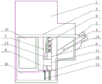
FIG. 1 is a schematic view of the overall structure of the present invention;
FIG. 2 is a schematic view of the internal structure of the protective shell according to the present invention;
FIG. 3 is a schematic view of the automatic switch structure of the present invention;
fig. 4 is a schematic diagram of the signal transmission structure controlled by the middle mobile terminal of the present invention.
In the figure: the circuit breaker comprises a circuit breaker body 1, an operating handle 2, a protective shell 3, a motion arm 4, a motion groove 5, a sliding elastic block 6, a slide bar 7, a spring 8, a slide rail table 9, a mounting table 10, an adsorption motion block 11, an electromagnet 12, a lead screw 13, a micro motor 14, an integrated control box 15, a storage battery 16, a single chip microcomputer 17, a wireless signal transmission module 18, a current detection module 19, a battery control module 20, a moving end 21, a first shaft lever 22, a second shaft lever 23, a third shaft lever 24 and a rotary hole 25.
Detailed Description
The technical solutions in the embodiments of the present invention will be described clearly and completely with reference to the accompanying drawings in the embodiments of the present invention, and it is obvious that the described embodiments are only some embodiments of the present invention, not all embodiments. Based on the embodiments in the present invention, all other embodiments obtained by a person skilled in the art without creative work belong to the protection scope of the present invention.
Example one
Referring to fig. 1-3, an automatic switch structure of a power circuit breaker includes a circuit breaker body 1, an operating handle 2 is disposed on the circuit breaker body 1, the opening and closing of the circuit breaker body 1 can be controlled by the operating handle 2, an automatic switch structure is disposed on one side of the circuit breaker body 1, the automatic switch structure includes a protective shell 3, a moving arm 4, a sliding elastic block 6 and an adsorption moving block 11, the protective shell 3 is fixedly connected to one side wall of the circuit breaker body 1, one end of the operating handle 2 close to the protective shell 3 is rotatably connected to the moving arm 4, a moving groove 5 is disposed on the protective shell 3, the moving arm 4 passes through the moving groove 5, the middle position of the moving arm 4 in the protective shell 3 is rotatably connected to the side wall of the circuit breaker body 1, the other end of the moving arm 4 is rotatably connected to the sliding elastic block 6, thus the moving arm 4 forms a lever structure, a sliding bar 7 is, the sliding elastic block 6 is provided with a sliding groove, the sliding strip 7 is connected with the sliding groove in a sliding manner, so that the sliding elastic block can slide on the sliding strip 7 in a linear manner, a spring 8 is fixedly connected between the top of the sliding elastic block 6 and the top of the protective shell 3, when the operating handle 2 is in a switching-on state, the spring 8 is in a stretching state, two groups of sliding rail platforms 9 are fixedly connected in front of the sliding elastic block 6 in the protective shell 3, the bottoms of the sliding rail platforms 9 are fixedly connected on an installation platform 10, the installation platform 10 is fixedly connected on the protective shell 3, an adsorption moving block 11 is slidably connected between the two groups of sliding rail platforms 9, the adsorption moving block 11 is provided with an electromagnet 12 corresponding to the bottom embedded of the sliding elastic block 6, a screw hole is arranged on the adsorption moving block 11, a group of lead screws 13 is connected with the screw hole in a threaded manner, the top ends of the lead screws, the lead screw 13 can be driven to rotate by the micro motor 14, so that the adsorption motion block 11 slides on the slide rail table 9, and the sliding direction of the adsorption motion table can be controlled by controlling the positive and negative rotation of the micro motor 14. The adsorption motion block 11 and the screw rod can also form a screw-nut mechanism. The lead screw is located between two slide rail platforms, can not interfere with the spring.
In this embodiment, the end of the operating handle 2 is fixedly connected with a first shaft rod 22, the sliding elastic block 6 is fixedly connected with a second shaft rod 23, the middle position of the moving arm 4 is fixedly connected with a third shaft rod 24, the two ends of the moving arm 4 are both provided with rotating holes 25, the rotating holes 25 are rotatably connected with the first shaft rod 22 and the second shaft rod 23, and the third shaft rod 24 is rotatably connected to the side wall of the circuit breaker body 1, so that various rotating connection effects of the moving arm 4 are realized;
set up the rail groove on the slide rail platform 9, all be provided with the slider on the both sides of adsorbing the motion piece 11, slider sliding connection is in the rail groove to this realizes adsorbing the sliding connection effect of motion piece 11 on slide rail platform 9.
Example two
Referring to fig. 2 and 4, in the first embodiment, an integrated control box 15 and a storage battery 16 are disposed inside a protective shell 3 of an automatic switch structure, a single chip microcomputer 17, a wireless signal transmission module 18, a current detection module 19 and a battery control module 20 are disposed inside the integrated control box 15, an electromagnet 12, a micro motor 14, the wireless signal transmission module 18, the current detection module 19 and the battery control module 20 are all in signal connection with the single chip microcomputer 17, the current detection module 19 is electrically connected with a circuit breaker body 1, the battery control module 20 is electrically connected with the storage battery 16 and the circuit breaker body 1, and the wireless signal transmission module 18 is wirelessly connected with a moving end 21, so as to control the automatic switch structure.
With the structure, the single chip microcomputer 17 is used for sending corresponding instruction signals according to logic programming;
the wireless signal transmission module 18 is used for realizing wireless transmission of signals;
the current detection module 19 is used for detecting the current inside the circuit breaker body 1;
the battery control module 20 is used for controlling the storage battery 16 and realizing the charging and discharging work of the storage battery 16;
the mobile terminal 21 is used for sending a control instruction, the control instruction includes a breaking instruction, a closing instruction and a restarting instruction, the breaking instruction and the closing instruction are suitable for being used when the breaker body 1 is not automatically broken, and the restarting instruction is suitable for being used after the breaker is automatically broken;
after the moving end 21 sends a breaking instruction, the automatic switch structure controls the circuit breaker body 1 according to the instruction to realize circuit breaking;
after the moving end 21 sends a closing instruction, the automatic switch structure controls the circuit breaker body 1 which is broken according to the instruction to realize circuit connection;
when the circuit breaker body 1 is overloaded by current, and the circuit breaking protection function is realized, the automatic switch structure can be matched with corresponding action, so that the circuit of the circuit breaker body 1 is broken;
after the circuit breaker body 1 breaks, the mobile terminal 21 can send a restart instruction, and the automatic switch structure controls the circuit breaker body 1 according to the instruction to realize the circuit re-connection.
In this embodiment, the mobile terminal 21 is a mobile phone, a corresponding APP is provided in the mobile phone, and the wireless signal transmission module 18 is a 4g module.
EXAMPLE III
Referring to fig. 1-4, according to the first and second embodiments, the present embodiment provides the specific working method of the present invention:
after the moving end 21 sends a circuit breaking instruction, the wireless signal transmission module 18 receives the circuit breaking instruction and transmits the circuit breaking instruction to the single chip microcomputer 17, the single chip microcomputer 17 controls the micro motor 14 to rotate according to the circuit breaking instruction, so that the micro motor 14 drives the screw rod 13 to rotate, the adsorption moving block 11 moves upwards on the sliding rail table 9, the adsorption moving block 11 pushes the elastic sliding block, the moving arm 4 is pulled to move upwards, and at the moment, due to the lever effect, the moving arm 4 can drive the operating handle 2 to press downwards, so that the circuit breaking of the circuit breaker body 1 is cut off;
after the circuit breaker is cut off, the shell of the moving end 21 sends a closing instruction, the wireless signal transmission module 18 receives the closing instruction and transmits the closing instruction to the single chip microcomputer 17, the single chip microcomputer 17 controls the micro motor 14 to rotate according to the closing instruction, so that the micro motor 14 drives the screw rod 13 to rotate, the adsorption moving block 11 moves downwards on the sliding rail table 9, at the moment, the electromagnet 12 adsorbs the elastic sliding block, the adsorption moving block 11 drives the elastic sliding block to move downwards, the moving arm 4 is pulled downwards, at the moment, the moving arm 4 drives the operating handle 2 to lift upwards due to the lever effect, and the circuit breaker body 1 is closed;
when the circuit breaker body 1 realizes an automatic protection function due to current overload, the current detection module 19 also detects the current overload, the current detection module 19 transmits an overload signal to the single chip microcomputer 17, and the single chip microcomputer 17 controls the electromagnet 12 to be powered off, so that the electromagnet 12 cannot adsorb the elastic sliding block when the operating handle 2 automatically falls, and the operating handle 2 can quickly fall due to the action of the spring 8, so that a circuit of the circuit breaker body 1 is cut off;
when the circuit breaker is automatically switched off due to automatic protection, a restart instruction can be sent through the moving end 21, the wireless signal transmission module 18 receives the restart instruction and transmits the restart instruction to the single chip microcomputer 17, the single chip microcomputer 17 controls the micro motor 14 to rotate according to the restart instruction, meanwhile, the micro motor 14 drives the lead screw 13 to rotate, the adsorption moving block 11 is enabled to move upwards on the sliding rail table 9, the single chip microcomputer 17 controls the electromagnet 12 to magnetize until the adsorption moving block 11 moves to the bottom of the elastic sliding block, the electromagnet 12 adsorbs the elastic sliding block, then, the single chip microcomputer 17 controls the micro motor 14 again, the adsorption moving block 11 drives the elastic sliding block to move downwards until the operating handle 2 is lifted through the moving arm 4, and switching-on of the circuit breaker body 1 is achieved.
It is obvious to a person skilled in the art that the invention is not restricted to details of the above-described exemplary embodiments, but that it can be implemented in other specific forms without departing from the spirit or essential characteristics of the invention. The present embodiments are therefore to be considered in all respects as illustrative and not restrictive, the scope of the invention being indicated by the appended claims rather than by the foregoing description, and all changes which come within the meaning and range of equivalency of the claims are therefore intended to be embraced therein. Any reference sign in a claim should not be construed as limiting the claim concerned.
Furthermore, it should be understood that although the present description refers to embodiments, not every embodiment may contain only a single embodiment, and such description is for clarity only, and those skilled in the art should integrate the description, and the embodiments may be combined as appropriate to form other embodiments understood by those skilled in the art.
Claims (4)
1. The utility model provides an automatic switch structure of power circuit breaker, includes circuit breaker body (1), be provided with operating handle (2) on circuit breaker body (1), its characterized in that: the automatic switch structure is arranged on one side of the circuit breaker body (1), and comprises a protective shell (3), a moving arm (4), a sliding elastic block (6) and an adsorption moving block (11), wherein the protective shell (3) is fixedly connected onto one side wall of the circuit breaker body (1), one end, close to the protective shell (3), of an operating handle (2) is rotatably connected with the moving arm (4), a moving groove (5) is formed in the protective shell (3), the moving arm (4) penetrates through the moving groove (5), the middle position of the moving arm (4) in the protective shell (3) is rotatably connected onto the side wall of the circuit breaker body (1), the other end of the moving arm (4) is rotatably connected onto the sliding elastic block (6), a sliding strip (7) is fixedly connected onto the side wall of the circuit breaker body (1) corresponding to the sliding elastic block (6), the sliding elastic block (6) is provided with a sliding groove, the sliding strip (7) is in sliding connection with the sliding groove, a spring (8) is fixedly connected between the top of the sliding elastic block (6) and the top of the protective shell (3), two groups of sliding rail tables (9) are fixedly connected in front of the sliding elastic block (6) in the protective shell (3), the bottoms of the sliding rail tables (9) are fixedly connected on an installation table (10), the installation table (10) is fixedly connected on the protective shell (3), the adsorption moving block (11) is in sliding connection between the two groups of sliding rail tables (9), the adsorption moving block (11) is provided with an electromagnet (12) corresponding to the bottom embedded part of the sliding elastic block (6), the adsorption moving block (11) is provided with a screw hole, the screw hole is in threaded connection with a group of screw rods (13), and the top end of each screw rod (13) is rotatably connected on the protective shell (3), the bottom end of the screw rod (13) penetrates through the mounting table (10) and is fixedly connected with a micro motor (14) fixedly connected to the bottom of the mounting table (10).
2. An automatic switch structure of a power circuit breaker according to claim 1, characterized in that: the protection shell (3) is internally provided with an integrated control box (15) and a storage battery (16), the integrated control box (15) is internally provided with a single chip microcomputer (17), a wireless signal transmission module (18), a current detection module (19) and a battery control module (20), the electromagnet (12), the micro motor (14), the wireless signal transmission module (18), the current detection module (19) and the battery control module (20) are all connected with the single chip microcomputer (17) through signals, the current detection module (19) is electrically connected with the circuit breaker body (1), the battery control module (20) is electrically connected with the storage battery (16) and the circuit breaker body (1), and the wireless signal transmission module (18) is wirelessly connected with a mobile terminal (21).
3. An automatic switch structure of a power circuit breaker according to claim 1, characterized in that: the end fixedly connected with first axostylus axostyle (22) of operating handle (2), fixedly connected with second axostylus axostyle (23) is gone up in slip bullet piece (6), the middle part position fixedly connected with third axostylus axostyle (24) of motion arm (4), the both ends of motion arm (4) all are provided with changes hole (25), change hole (25) with first axostylus axostyle (22), second axostylus axostyle (23) rotate and are connected, third axostylus axostyle (24) rotate and are connected on the lateral wall of circuit breaker body (1).
4. An automatic switch structure of a power circuit breaker according to claim 1, characterized in that: the slide rail table (9) is provided with a rail groove, the two sides of the adsorption motion block (11) are provided with slide blocks, and the slide blocks are connected in the rail groove in a sliding mode.
Priority Applications (1)
| Application Number | Priority Date | Filing Date | Title |
|---|---|---|---|
| CN202022123608.7U CN213519793U (en) | 2020-09-25 | 2020-09-25 | Automatic switch structure of power circuit breaker |
Applications Claiming Priority (1)
| Application Number | Priority Date | Filing Date | Title |
|---|---|---|---|
| CN202022123608.7U CN213519793U (en) | 2020-09-25 | 2020-09-25 | Automatic switch structure of power circuit breaker |
Publications (1)
| Publication Number | Publication Date |
|---|---|
| CN213519793U true CN213519793U (en) | 2021-06-22 |
Family
ID=76449843
Family Applications (1)
| Application Number | Title | Priority Date | Filing Date |
|---|---|---|---|
| CN202022123608.7U Active CN213519793U (en) | 2020-09-25 | 2020-09-25 | Automatic switch structure of power circuit breaker |
Country Status (1)
| Country | Link |
|---|---|
| CN (1) | CN213519793U (en) |
-
2020
- 2020-09-25 CN CN202022123608.7U patent/CN213519793U/en active Active
Similar Documents
| Publication | Publication Date | Title |
|---|---|---|
| CN112185771A (en) | Automatic switch structure of power circuit breaker and control system thereof | |
| CN213519793U (en) | Automatic switch structure of power circuit breaker | |
| CN201167247Y (en) | Operating mechanism for intelligent double-power supply throwing-cutting apparatus | |
| CN103065884B (en) | automatic reclosing controller | |
| CN203596327U (en) | Energy storage system of breaker operation mechanism | |
| CN214411096U (en) | Switching-on and switching-off driving and controlling device of intelligent circuit breaker | |
| CN204497163U (en) | A kind of circuit breaker failure tripping indicating device | |
| CN205028871U (en) | Miniature circuit breaker control structure and contain miniature circuit breaker controlling means of this structure | |
| CN210015829U (en) | Electric switching-on and switching-off device of air circuit breaker | |
| CN208336127U (en) | A kind of motor-operating mechanism | |
| CN205984791U (en) | Outdoor monopole vacuum circuit breaker for railway | |
| CN215680592U (en) | Over-voltage and under-voltage protection device of small circuit breaker | |
| CN220208868U (en) | Remote control type low-voltage circuit breaker operating device | |
| CN201663071U (en) | Operation mechanism for dual-power switch | |
| CN219040385U (en) | Tripping structure of circuit breaker | |
| CN203205359U (en) | Auto-reclosing controller | |
| CN204332854U (en) | A kind of transmission device of auxiliary switch for circuit breaker | |
| CN219202989U (en) | Breaker equipment running-in device | |
| CN215497695U (en) | Full-automatic control system of high tension switchgear | |
| CN209328825U (en) | A kind of permanent magnet mechanism Electronic Control Assembly of gas insulation breaker cabinet | |
| CN109786147B (en) | Automatic transfer switch electric appliance with re-buckling function | |
| CN216213210U (en) | Transmission system and circuit breaker | |
| CN117219476B (en) | High-safety automatic reset circuit breaker | |
| CN220821437U (en) | Portable thing networking circuit breaker of wiring | |
| CN110120319B (en) | Vertical telescopic pneumatic high-voltage isolating switch |
Legal Events
| Date | Code | Title | Description |
|---|---|---|---|
| GR01 | Patent grant | ||
| GR01 | Patent grant |