CN213506897U - Fermentation cylinder convenient to adjust - Google Patents
Fermentation cylinder convenient to adjust Download PDFInfo
- Publication number
- CN213506897U CN213506897U CN202021077460.1U CN202021077460U CN213506897U CN 213506897 U CN213506897 U CN 213506897U CN 202021077460 U CN202021077460 U CN 202021077460U CN 213506897 U CN213506897 U CN 213506897U
- Authority
- CN
- China
- Prior art keywords
- stirring
- rod
- fixed mounting
- electric telescopic
- stirring shell
- Prior art date
- Legal status (The legal status is an assumption and is not a legal conclusion. Google has not performed a legal analysis and makes no representation as to the accuracy of the status listed.)
- Active
Links
Images


Abstract
The utility model discloses a fermentation tank convenient to adjust, which comprises a fixed base, a fixed frame is fixedly arranged at the top of the fixed base, a stirring mechanism is fixedly arranged at one side of the fixed frame, a groove is arranged at the top of the fixed frame, a first stirring shell is fixedly arranged at the bottom end of the groove opposite to a position, a second stirring shell is fixedly arranged at the bottom end of the first stirring shell, a mixing mechanism is respectively and fixedly arranged at two sides of the second stirring shell, the scheme pushes a slide block on a connecting rod upwards through the extension and retraction of a first electric telescopic rod, the slide block drives a support rod to move up and down through the sliding of the slide block, the stirring fan blades are convenient to move up and down, the horizontal position of a servo motor on an L-shaped rod is driven to be adjusted through the up and down movement of the support rod, the stirring fan blades on the rotating rod at the bottom end are driven to rotate, make things convenient for stirring fan blade to pass through the fluting, improve the efficiency of stirring.
Description
Technical Field
The utility model relates to the technical field of machining, specifically be a fermentation cylinder convenient to adjust.
Background
A fermenter refers to an apparatus used industrially for carrying out microbial fermentation. The main body is generally a main cylinder made of stainless steel plate, and the volume of the main cylinder is 1m3 to hundreds m 3. In the design and processing, attention should be paid to the structure is tight and reasonable, the steam sterilization can be endured, certain operation elasticity is provided, the internal accessories are reduced as much as possible (dead angles are avoided), the material and energy transfer performance is strong, certain adjustment can be carried out so as to facilitate cleaning and reduce pollution, and the steam sterilization machine is suitable for the production of various products and reduces energy consumption.
Along with the continuous development of modern chemical industry, traditional anti-fermentation cylinder is not convenient for adjust the reaction effect that influences between raw materials and the interpolation material agent to the agitator when mixing between raw materials and the interpolation material agent, and the reaction is ended and is not convenient for clear up the inside of fermentation cylinder.
SUMMERY OF THE UTILITY MODEL
An object of the utility model is to provide a supply fermentation cylinder convenient to adjust to when traditional anti-fermentation jar mixes between raw materials and interpolation material agent on solving the existing market that above-mentioned background art provided, be not convenient for adjust the agitator and influence the raw materials and add the reaction effect between the material agent, the reaction finishes the problem of the inside problem of clearing up of the fermentation cylinder of being not convenient for.
In order to achieve the above object, the utility model provides a following technical scheme: the utility model provides a fermentation cylinder convenient to adjust, includes the fixing base, the top fixed mounting of fixing base has fixed frame, one side fixed mounting of fixed frame has rabbling mechanism, the fluting has been seted up at fixed frame's top, the fluting bottom is just being provided with first stirring shell to the position department is fixed, the bottom fixed mounting of first stirring shell has second stirring shell, the both sides of second stirring shell are fixed mounting respectively has mixing mechanism.
Preferably, the stirring mechanism comprises a supporting block fixedly connected with one side of the fixed frame, a rod post is fixedly mounted at the top of the supporting block, a groove is formed in the rod post, a connecting rod is fixedly mounted in the groove, a sliding block is slidably connected to the outer side of the connecting rod, one side of the sliding block is fixedly connected with one end of the supporting rod, a first electric telescopic rod is fixedly mounted at the bottom end of the sliding block, an L-shaped rod is fixedly mounted at the top of the other end of the supporting rod, a servo motor is fixedly mounted at the top of the L-shaped rod, a rotating rod is fixedly mounted at the output end of the servo motor, three second electric telescopic rods are arranged on the outer side of the bottom end of the rotating rod, and stirring fan blades are.
Preferably, two the mixing mechanism include with second stirring shell one side fixed mounting have the bumper shock absorber, one side fixed mounting of bumper shock absorber has driving motor, driving motor's one end fixed mounting has the dwang, the one end fixed mounting of dwang has the stirring leaf.
Preferably, the top of the fixed seat is fixedly provided with an LED illuminating lamp.
Preferably, one side fixed mounting of fixing base has the PLC controller, first electric telescopic handle, servo motor, second electric telescopic handle and LED light and PLC controller electric connection.
Compared with the prior art, the beneficial effects of the utility model are that:
(1) through the flexible of the first electric telescopic handle that sets up, slider on the connecting rod upwards promotes, drive the bracing piece then through the slip of slider and reciprocate, the stirring fan blade of being convenient for reciprocates, the horizontal position's of servo motor on driving L type pole adjustment then through the removal about the bracing piece, the stirring fan blade on the bull stick of rotation drive bottom through servo motor rotates, the flexible adjustment stirring fan blade that is convenient for through second electric telescopic handle extends the face, make things convenient for stirring fan blade to pass through the fluting, the efficiency of stirring is improved.
Drawings
Fig. 1 is a schematic structural diagram of the present invention;
fig. 2 is one of the schematic structural diagrams of the present invention;
fig. 3 is a second schematic structural diagram of the present invention;
fig. 4 is a schematic structural view of a driving motor in the present invention;
fig. 5 is a schematic view of the structure of the post of the present invention.
In the figure: 101. a fixed seat; 102. a fixed frame; 103. a stirring mechanism; 104. grooving; 105. a first stirring shell; 106. a second stirring shell; 107. a mixing mechanism; 108. a support block; 109. a post; 110. a groove; 111. a connecting rod; 112. a slider; 113. a support bar; 114. a first electric telescopic rod; 115. an L-shaped rod; 116. a servo motor; 117. a rotating rod; 118. a second electric telescopic rod; 119. a stirring fan blade; 120. a shock absorber; 121. a drive motor; 122. rotating the rod; 123. stirring the leaves.
Detailed Description
The technical solutions in the embodiments of the present invention will be described clearly and completely with reference to the accompanying drawings in the embodiments of the present invention, and it is obvious that the described embodiments are only some embodiments of the present invention, not all embodiments. Based on the embodiments in the present invention, all other embodiments obtained by a person skilled in the art without creative work belong to the protection scope of the present invention.
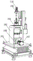
Referring to fig. 1-5, the present invention provides a technical solution: the utility model provides a fermentation cylinder convenient to adjust, includes fixing base 101, and the top fixed mounting of fixing base 101 has fixed frame 102, and one side fixed mounting of fixed frame 102 has rabbling mechanism 103, and fluting 104 has been seted up at fixed frame 102's top, and fluting 104 bottom is just to the fixed first stirring shell 105 that is provided with of position department, and the bottom fixed mounting of first stirring shell 105 has second stirring shell 106, and the both sides difference fixed mounting of second stirring shell 106 has mixing mechanism 107.
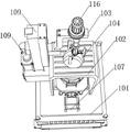
In this embodiment, the stirring mechanism 103 includes a supporting block 108 fixedly connected to one side of the fixed frame 102, a rod column 109 is fixedly mounted at the top of the supporting block 108, a groove 110 is formed inside the rod column 109, a connecting rod 111 is fixedly mounted inside the groove 110, a slider 112 is slidably connected to the outer side of the connecting rod 111, one side of the slider 112 is fixedly connected to one end of a supporting rod 113, a first electric telescopic rod 114 is fixedly mounted at the bottom end of the slider 112, an L-shaped rod 115 is fixedly mounted at the top of the other end of the supporting rod 113, a servo motor 116 is fixedly mounted at the top of the L-shaped rod 115, a rotating rod 117 is fixedly mounted at the output end of the servo motor 116, three second electric telescopic rods 118 are arranged at the outer side of the bottom end of the rotating.
Specifically, when stirring the inside material of first stirring shell 105, at first through the flexible of first electric telescopic handle 114, slider 112 on connecting rod 111 upwards promotes, slider 112's slip drives bracing piece 113 then and reciprocates, the removal about bracing piece 113 drives servo motor 116's on the L type pole 115 horizontal position's adjustment then, make servo motor 116 rotate through the PLC controller, stirring fan blade 119 on the bull stick 117 that drives the bottom through servo motor 116's rotation rotates, be convenient for adjust stirring fan blade 119 expansion face through the flexible of second electric telescopic handle 118, make things convenient for stirring fan blade 119 to pass through fluting 104, the efficiency of stirring is improved.
In this embodiment, the two mixing mechanisms 107 include a damper 120 fixedly mounted on one side of the second stirring shell 106, a driving motor 121 fixedly mounted on one side of the damper 120, a rotating rod 122 fixedly mounted on one end of the driving motor 121, and a stirring blade 123 fixedly mounted on one end of the rotating rod 122.
Specifically, the driving motor 121 is convenient to absorb shock in the rotating process through the use of the shock absorber 120, and the stirring blade 123 which drives one end of the rotating rod 122 to stir in the second stirring shell 106 through the rotation of the driving motor 121, so that the stirring efficiency is improved.
In this embodiment, an LED lighting lamp is fixedly mounted on the top of the fixing base 101.
In particular, it is convenient to illuminate the workers who operate at night.
In this embodiment, a PLC controller is fixedly mounted on one side of the fixing base 101, and the first electric telescopic rod 114, the servo motor 116, the second electric telescopic rod 118 and the LED lighting lamp are electrically connected to the PLC controller.
Specifically, be convenient for through the PLC controller control the equipment on the fermentation cylinder of adjusting.
Although the present invention has been described in detail with reference to the foregoing embodiments, it will be apparent to those skilled in the art that modifications and equivalents may be made without departing from the spirit and scope of the invention.
Claims (5)
1. The utility model provides a fermentation cylinder convenient to adjust, includes fixing base (101), its characterized in that, the top fixed mounting of fixing base (101) has fixed frame (102), one side fixed mounting of fixed frame (102) has rabbling mechanism (103), fluting (104) have been seted up at the top of fixed frame (102), fluting (104) bottom is just fixed being provided with first stirring shell (105) to position department, the bottom fixed mounting of first stirring shell (105) has second stirring shell (106), the both sides difference fixed mounting of second stirring shell (106) has mixing mechanism (107).
2. The fermenter of claim 1, wherein: the stirring mechanism (103) comprises a supporting block (108) fixedly connected with one side of a fixed frame (102), a rod column (109) is fixedly installed at the top of the supporting block (108), a groove (110) is formed in the rod column (109), a connecting rod (111) is fixedly installed in the groove (110), a sliding block (112) is slidably connected to the outer side of the connecting rod (111), one side of the sliding block (112) is fixedly connected with one end of a supporting rod (113), a first electric telescopic rod (114) is fixedly installed at the bottom end of the sliding block (112), an L-shaped rod (115) is fixedly installed at the top of the other end of the supporting rod (113), a servo motor (116) is fixedly installed at the top of the L-shaped rod (115), a rotating rod (117) is fixedly installed at the output end of the servo motor (116), and three second electric telescopic rods (118) are arranged on the outer side of the bottom end, one end of the second electric telescopic rod (118) is fixedly provided with a stirring fan blade (119).
3. A fermenter for facilitating the adjustment according to claim 2, wherein: two mixing mechanism (107) include with second stirring shell (106) one side fixed mounting's bumper shock absorber (120), one side fixed mounting of bumper shock absorber (120) has driving motor (121), the one end fixed mounting of driving motor (121) has dwang (122), the one end fixed mounting of dwang (122) has stirring leaf (123).
4. A fermenter of claim 3, wherein: and the top of the fixed seat (101) is fixedly provided with an LED illuminating lamp.
5. The fermenter of claim 4, wherein: one side fixed mounting of fixing base (101) has the PLC controller, first electric telescopic handle (114), servo motor (116), second electric telescopic handle (118) and LED light and PLC controller electric connection.
Priority Applications (1)
| Application Number | Priority Date | Filing Date | Title |
|---|---|---|---|
| CN202021077460.1U CN213506897U (en) | 2020-06-12 | 2020-06-12 | Fermentation cylinder convenient to adjust |
Applications Claiming Priority (1)
| Application Number | Priority Date | Filing Date | Title |
|---|---|---|---|
| CN202021077460.1U CN213506897U (en) | 2020-06-12 | 2020-06-12 | Fermentation cylinder convenient to adjust |
Publications (1)
| Publication Number | Publication Date |
|---|---|
| CN213506897U true CN213506897U (en) | 2021-06-22 |
Family
ID=76379989
Family Applications (1)
| Application Number | Title | Priority Date | Filing Date |
|---|---|---|---|
| CN202021077460.1U Active CN213506897U (en) | 2020-06-12 | 2020-06-12 | Fermentation cylinder convenient to adjust |
Country Status (1)
| Country | Link |
|---|---|
| CN (1) | CN213506897U (en) |
-
2020
- 2020-06-12 CN CN202021077460.1U patent/CN213506897U/en active Active
Similar Documents
| Publication | Publication Date | Title |
|---|---|---|
| CN108788277A (en) | A kind of ductile iron pipe processing cutting equipment | |
| CN209364949U (en) | It is a kind of for processing the blank remedying device of porcelain tube | |
| CN211945181U (en) | Spreading device of aquatic product processing machine | |
| CN213506897U (en) | Fermentation cylinder convenient to adjust | |
| CN209793328U (en) | Grinding device is used in transformer production | |
| CN213652469U (en) | Portable fermentation cylinder for food processing | |
| CN201380552Y (en) | Wallboard cutting machine | |
| CN203566797U (en) | Feeding mechanism of numerical control cut-to-size saw | |
| CN116116361A (en) | Self-cleaning reaction kettle with variable-speed stirring function | |
| CN217313117U (en) | Mixing arrangement is used in production of multidirectional stirring formula water proof coating | |
| CN212819550U (en) | Coating material mixing and stirring equipment with high automation degree | |
| CN214022872U (en) | Stainless steel drawing machine easy to operate | |
| CN213036895U (en) | Device for clamping raw material and driving rotation by using cylinder | |
| CN210111904U (en) | Self-cleaning solar photovoltaic support | |
| CN209938060U (en) | Novel UV flatbed printer's location device | |
| CN213314992U (en) | Reaction kettle stirring device with adjusting structure | |
| CN202123419U (en) | Novel aluminum product circular arc polishing machine | |
| CN219005442U (en) | Gear processing blowing device | |
| CN202123420U (en) | Reciprocating rotary swing table device applied to aluminum arc polishing machine | |
| CN215428662U (en) | Rapid stirring and dispersing equipment for preparing florfenicol solution microemulsion | |
| CN219463189U (en) | Glass lining reaction kettle for retarder production | |
| CN209439709U (en) | The woodruff key mounting device of angle grinder front cover | |
| CN219249181U (en) | Slurry hanging machine for producing fish products | |
| CN213624115U (en) | A fermentation cylinder for microbial inoculum production | |
| CN219939568U (en) | Fermentation tank |
Legal Events
| Date | Code | Title | Description |
|---|---|---|---|
| GR01 | Patent grant | ||
| GR01 | Patent grant |