CN213505609U - Rotor hoisting device of sand making machine - Google Patents
Rotor hoisting device of sand making machine Download PDFInfo
- Publication number
- CN213505609U CN213505609U CN202022583443.1U CN202022583443U CN213505609U CN 213505609 U CN213505609 U CN 213505609U CN 202022583443 U CN202022583443 U CN 202022583443U CN 213505609 U CN213505609 U CN 213505609U
- Authority
- CN
- China
- Prior art keywords
- welded
- rotor
- hoisting
- block
- lead screw
- Prior art date
- Legal status (The legal status is an assumption and is not a legal conclusion. Google has not performed a legal analysis and makes no representation as to the accuracy of the status listed.)
- Active
Links
Images


Abstract
The utility model discloses a system sand machine rotor hoist device, including playing the gallows, it has solid fixed ring to play the welding on the side surface of gallows, the lower skin weld of playing the gallows has the fixed block, the welding has the second chuck on the fixed block side table wall, play the upper surface of gallows and seted up first slide rail on the length direction central line, first slide rail both ends respectively weld there is a spacing, sliding connection has the slider in the first slide rail, the last skin weld of slider has rings, rings and slider respectively are provided with two. The utility model discloses in, at the in-process that uses, after the rotor centre gripping of system sand machine, before hoist and mount, need the staff to remove rings on first slide rail, guarantee that the rotor focus of system sand machine and the focus of gallows are on the same perpendicular line, prevent to hoist and mount in-process focus and take place the skew, and lead to the rotor of system sand machine to take place to drop.
Description
Technical Field
The utility model relates to a general mechanical equipment makes technical field, especially relates to a system sand machine rotor hoist device.
Background
The sand making machine is widely applied to various departments such as large, smelting, building materials, roads, railways, water conservancy, chemical industry and the like, when the working time of the sand making machine is longer, a rotor needs to be replaced or maintained, when the rotor of the sand making machine is maintained or assembled, the rotor needs to be inserted into a stator, and the rotor of the sand making machine is larger, so that the sand making machine is more troublesome to carry and has low working efficiency.
When the existing sand making machine rotor is maintained or assembled, the clamping mechanism of the existing hoisting device cannot change the clamping distance, so that the existing sand making machine rotor cannot be suitable for various models, the existing hoisting ring of the hoisting device cannot be moved, the gravity center of the rotor cannot be easily shifted to fall off at the center of the hoisting frame when hoisting is caused, and the personal safety of workers is threatened.
SUMMERY OF THE UTILITY MODEL
The utility model aims at solving the shortcoming that exists among the prior art, and the system sand machine rotor of the applicable multiple different models that provides, according to the center of the different rotors before lifting by crane and change the position of rings, make a system sand machine rotor hoist device that the hoist and mount process is safer.
In order to achieve the above purpose, the utility model adopts the following technical scheme: a rotor hoisting device of a sand making machine comprises a hoisting frame, wherein a fixing ring is welded on the side surface of the hoisting frame, a fixing block is welded on the lower surface of the hoisting frame, a second chuck is welded on the side surface wall of the fixing block, a first slide rail is arranged on the upper surface of the hoisting frame along the length direction central line, two limiting strips are welded at two ends of the first slide rail respectively, a slide block is connected in the first slide rail in a sliding manner, a hoisting ring is welded on the upper surface of the slide block, the hoisting ring and the slide block are respectively provided with two hoisting rings, a second slide rail is arranged on the lower surface of the hoisting frame along the length direction central line, a screw motor is fixed on the outer surface wall of one side of the hoisting frame, which is far away from the fixing ring, a screw rod is connected on the output shaft of the screw rod in a rotating manner through a shaft coupling, a first bearing is sleeved at one, the safety device is characterized in that a screw nut seat is connected to the screw in a threaded manner, a movable block is welded to the screw nut seat, a first chuck is welded to the side surface wall of the movable block, a rotating rod is connected to the lower surface of the movable block in a rotating manner, and a safety plate is welded to the bottom end of the rotating rod.
Preferably, the first chuck has seted up the jack catch groove on the table wall outward, and the inside sliding connection in jack catch groove has the jack catch, the inside welding in jack catch groove has the fixing base, threaded connection has the threaded rod on the fixing base, and the one end of threaded rod runs through the fixing base and extends to the outside and weld and have the second bearing, second bearing welded fastening is on the jack catch, be provided with the rubber pad on the jack catch.
Preferably, four clamping jaw grooves are formed in the clamping jaw groove, the four clamping jaw grooves are distributed in an annular shape, and included angles between every two adjacent clamping jaw grooves are equal.
Preferably, a limiting block is welded on the surface wall of the other side of the movable block, a limiting pipe is welded on the surface wall of the side of the rotating rod, and a limiting pin is inserted into the limiting pipe and the limiting block.
Preferably, the side surface wall of the lifting frame is provided with a limit pin, and the limit pin penetrates through the lifting frame and extends to the inside of the first slide rail to be inserted into the slide block.
Compared with the prior art, the beneficial effects of the utility model are that:
1. the utility model discloses in, this system sand machine rotor hoist device is provided with two chucks altogether, and first chuck is fixed on the movable block, and at the in-process that uses, through opening lead screw motor, drive the motion of screw nut seat, make the motion of the movable block of fixing on the screw nut seat, the effect chuck through lead screw motor can carry out the centre gripping to the system sand machine rotor of different models, and the movable block all is provided with the safety plate with the fixed block below in the hoist and mount, can prevent that the in-process rotor from taking place to drop and cause the injury to the staff.
2. The utility model discloses in, this system sand machine rotor hoist device, at the in-process that uses, after the rotor centre gripping of system sand machine, before hoist and mount, need the staff to remove rings on first slide rail, guarantee that the rotor focus of system sand machine and the focus of play gallows are on the same vertical line, prevent to hoist and mount in-process focus and take place the skew, and lead to the rotor of system sand machine to take place to drop.
Drawings
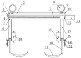
Fig. 1 is a schematic structural view of a rotor hoisting device of a sand making machine provided by the utility model;
fig. 2 is a side view of a rotor hoisting device of a sand making machine provided by the utility model;
fig. 3 is the utility model provides a system sand machine rotor hoist device's structural schematic of first chuck.
Illustration of the drawings:
1. lifting the hanger; 2. a first slide rail; 3. a fixing ring; 4. a first bearing; 5. a second slide rail; 6. a fixed block; 7. a lead screw; 8. lifting a lifting ring; 9. a slider; 91. a limit pin; 10. a limiting strip; 11. a lead screw motor; 12. a lead screw nut seat; 13. a movable block; 14. a first chuck; 141. a jaw slot; 142. a fixed seat; 143. a threaded rod; 144. a claw; 145. a second bearing; 146. a rubber pad; 15. a spacing pin; 151. a limiting block; 152. a limiting pipe; 16. a rotating rod; 17. a security pane; 18. a second chuck.
Detailed Description
The technical solutions in the embodiments of the present invention will be described clearly and completely with reference to the accompanying drawings in the embodiments of the present invention, and it is obvious that the described embodiments are only some embodiments of the present invention, not all embodiments. Based on the embodiments in the present invention, all other embodiments obtained by a person skilled in the art without creative work belong to the protection scope of the present invention.
In the description of the present invention, it should be noted that the terms "center", "upper", "lower", "left", "right", "vertical", "horizontal", "inner", "outer", and the like indicate orientations or positional relationships based on the orientations or positional relationships shown in the drawings, and are only for convenience of description and simplification of description, but do not indicate or imply that the device or element referred to must have a specific orientation, be constructed and operated in a specific orientation, and thus, should not be construed as limiting the present invention; the terms "first," "second," and "third" are used for descriptive purposes only and are not to be construed as indicating or implying relative importance; furthermore, unless expressly stated or limited otherwise, the terms "mounted," "connected," and "connected" are to be construed broadly, as they may be fixedly connected, detachably connected, or integrally connected, for example; can be mechanically or electrically connected; they may be connected directly or indirectly through intervening media, or they may be interconnected between two elements. The specific meaning of the above terms in the present invention can be understood in specific cases to those skilled in the art.
Referring to fig. 1-3, a rotor hoisting device of a sand making machine comprises a lifting frame 1, a fixing ring 3 is welded on the side surface of the lifting frame 1, a fixing block 6 is welded on the lower surface of the lifting frame 1, a second chuck 18 is welded on the side surface wall of the fixing block 6, a first slide rail 2 is arranged on the upper surface of the lifting frame 1 along the length direction central line, two limiting strips 10 are respectively welded on two ends of the first slide rail 2, a slide block 9 is connected in the first slide rail 2 in a sliding manner, a lifting ring 8 is welded on the upper surface of the slide block 9, two lifting rings 8 and two slide blocks 9 are respectively arranged, a second slide rail 5 is arranged on the lower surface of the lifting frame 1 along the length direction central line, a lead screw motor 11 is fixed on the outer surface wall of one side of the lifting frame 1 far away from the fixing ring 3 through a bolt, a lead screw 7 is rotatably connected on, and the first bearing 4 is welded and fixed on the inner surface wall of the second slide rail 5, the screw 7 is in threaded connection with a screw nut seat 12, a movable block 13 is welded on the screw nut seat 12, a first chuck 14 is welded on the surface wall on the side of the movable block 13, the lower surface of the movable block 13 is rotatably connected with a rotating rod 16, and the bottom end of the rotating rod 16 is welded with a safety plate 17.
The outer surface wall of the first chuck 14 is provided with a jaw groove 141, a jaw 144 is slidably connected to the inside of the jaw groove 141, a fixed seat 142 is welded to the inside of the jaw groove 141, a threaded rod 143 is connected to the fixed seat 142 in a threaded manner, one end of the threaded rod 143 penetrates through the fixed seat 142 and extends to the outside, a second bearing 145 is welded to the fixed seat 142, the second bearing 145 is welded to the jaw 144, and a rubber pad 146 is arranged on the jaw 144.
The number of the claw grooves 141 is four, the four claw grooves 141 are distributed annularly, and the included angles between two adjacent claw grooves 141 are equal.
The other side table wall of movable block 13 has welded stopper 151, and the side table wall of bull stick 16 has welded spacing pipe 152, and stopper 151 and spacing pipe 152 interpolation have been connected with spacer pin 15.
Be provided with stop pin 91 on the side table wall of play gallows 1, stop pin 91 runs through the inside grafting that plays gallows 1 and extend to first slide rail 2 on slider 9.
The working principle is as follows:
this a system sand machine rotor hoist device when using, advance jack catch 144 to open or contract through using twisting threaded rod 143 screw propulsion before hoist and mount earlier, make the rotor one end clamping of system sand machine fix on second chuck 18, start lead screw motor 11 simultaneously and drive first chuck 14 and move, make things convenient for the other end of centre gripping system sand machine rotor, after clamping process, after hoist and mount, before carrying out, remove rings 8 on first slide rail through the staff, make the rotor focus of system sand machine and the focus of lifting frame 1 be on the same vertical line, prevent that the rotor of system sand machine from taking place to drop, connect the haulage rope on solid fixed ring 3, the staff passes through the haulage rope, prevent that system sand machine rotor from rocking at the in-process of carrying out hoist and mount.
The above, only be the concrete implementation of the preferred embodiment of the present invention, but the protection scope of the present invention is not limited thereto, and any person skilled in the art is in the technical scope of the present invention, according to the technical solution of the present invention and the utility model, the concept of which is equivalent to replace or change, should be covered within the protection scope of the present invention.
Claims (5)
1. A rotor hoisting device of a sand making machine comprises a hoisting frame (1) and is characterized in that a fixing ring (3) is welded on the side surface of the hoisting frame (1), a fixing block (6) is welded on the lower surface of the hoisting frame (1), a second chuck (18) is welded on the side surface wall of the fixing block (6), a first sliding rail (2) is arranged on the upper surface of the hoisting frame (1) along the length direction center line, two limiting strips (10) are respectively welded at two ends of the first sliding rail (2), a sliding block (9) is connected in the first sliding rail (2) in a sliding manner, a hoisting ring (8) is welded on the upper surface of the sliding block (9), two hoisting rings (8) and two sliding blocks (9) are respectively arranged, a second sliding rail (5) is arranged on the lower surface of the hoisting frame (1) along the length direction center line, and a lead screw motor (11) is fixed on the outer surface wall of one side of the hoisting frame (1) far away from, and the output shaft of lead screw motor (11) is gone up to rotate through the shaft coupling and is connected with lead screw (7), first bearing (4) have been cup jointed to lead screw (7) one end, and first bearing (4) welded fastening is on the interior table wall of second slide rail (5), threaded connection has lead screw nut seat (12) on lead screw (7), the welding has movable block (13) on lead screw nut seat (12), the welding has first chuck (14) on movable block (13) side table wall, the lower surface of movable block (13) rotates and is connected with bull stick (16), the bottom welding of bull stick (16) has safety plate (17).
2. The rotor hoisting device for the sand making machine as claimed in claim 1, wherein a jaw groove (141) is formed in the outer surface wall of the first chuck (14), a jaw (144) is slidably connected to the inside of the jaw groove (141), a fixed seat (142) is welded inside the jaw groove (141), a threaded rod (143) is connected to the fixed seat (142) in a threaded mode, one end of the threaded rod (143) penetrates through the fixed seat (142) to extend to the outside, a second bearing (145) is welded to the fixed seat, the second bearing (145) is welded to the jaw (144), and a rubber pad (146) is arranged on the jaw (144).
3. The rotor hoisting device for the sand making machine as claimed in claim 2, wherein the number of the claw grooves (141) is four, the four claw grooves (141) are distributed annularly, and the included angles between two adjacent claw grooves (141) are equal.
4. The rotor hoisting device of the sand making machine as claimed in claim 1, wherein a limiting block (151) is welded on the surface wall of the other side of the movable block (13), a limiting pipe (152) is welded on the surface wall of the side of the rotating rod (16), and a limiting pin (15) is inserted into the limiting block (151) and the limiting pipe (152).
5. A rotor hoisting device for a sand making machine according to claim 1, characterized in that a limit pin (91) is arranged on the side surface wall of the lifting frame (1), and the limit pin (91) extends to the inside of the first slide rail (2) through the lifting frame (1) and is inserted into the slide block (9).
Priority Applications (1)
| Application Number | Priority Date | Filing Date | Title |
|---|---|---|---|
| CN202022583443.1U CN213505609U (en) | 2020-11-10 | 2020-11-10 | Rotor hoisting device of sand making machine |
Applications Claiming Priority (1)
| Application Number | Priority Date | Filing Date | Title |
|---|---|---|---|
| CN202022583443.1U CN213505609U (en) | 2020-11-10 | 2020-11-10 | Rotor hoisting device of sand making machine |
Publications (1)
| Publication Number | Publication Date |
|---|---|
| CN213505609U true CN213505609U (en) | 2021-06-22 |
Family
ID=76422616
Family Applications (1)
| Application Number | Title | Priority Date | Filing Date |
|---|---|---|---|
| CN202022583443.1U Active CN213505609U (en) | 2020-11-10 | 2020-11-10 | Rotor hoisting device of sand making machine |
Country Status (1)
| Country | Link |
|---|---|
| CN (1) | CN213505609U (en) |
Cited By (1)
| Publication number | Priority date | Publication date | Assignee | Title |
|---|---|---|---|---|
| CN113816257A (en) * | 2021-09-29 | 2021-12-21 | 广西玉柴机器股份有限公司 | Sand core hoisting equipment capable of adjusting width |
-
2020
- 2020-11-10 CN CN202022583443.1U patent/CN213505609U/en active Active
Cited By (2)
| Publication number | Priority date | Publication date | Assignee | Title |
|---|---|---|---|---|
| CN113816257A (en) * | 2021-09-29 | 2021-12-21 | 广西玉柴机器股份有限公司 | Sand core hoisting equipment capable of adjusting width |
| CN113816257B (en) * | 2021-09-29 | 2024-03-15 | 广西玉柴机器股份有限公司 | Sand core lifting device capable of adjusting width |
Similar Documents
| Publication | Publication Date | Title |
|---|---|---|
| CN213505609U (en) | Rotor hoisting device of sand making machine | |
| CN202449788U (en) | Special crane device for wall bricks | |
| CN215326725U (en) | Hoisting device for civil engineering building material installation | |
| CN212127258U (en) | Hoisting accessory for construction | |
| CN106541394A (en) | Reinforcement jaw and mechanical hand | |
| CN203199874U (en) | Automatic lifting tool for steel plates | |
| CN216004959U (en) | Electric single-beam portal crane for building construction | |
| CN215558390U (en) | Hoisting apparatus for fire control construction | |
| CN212387586U (en) | Building engineering lifting device | |
| CN211283481U (en) | Anti-swing pulley connecting device of grab crane | |
| CN213952926U (en) | Pulling-up hanging basket for construction of constructional engineering | |
| CN214326899U (en) | Hoisting equipment for prefabricated components of fabricated building | |
| CN220787869U (en) | Lifting platform for radial arm crane | |
| CN213257233U (en) | Automatic machine tool for machining pin holes of main angle steel of intermediate section of tower crane | |
| CN220787792U (en) | Traveling crane for steel structure production | |
| CN215160315U (en) | Chemical industry equipment hoisting accessory | |
| CN213202154U (en) | Hoisting device for civil engineering house building | |
| CN214087338U (en) | Steel structural member hoisting device | |
| CN212799412U (en) | Hoisting mechanism of heat treatment equipment | |
| CN217501622U (en) | Derrick for lifting outlet shaft well head | |
| CN217458571U (en) | Tower crane safety gap bridge device | |
| CN213710454U (en) | Building wall device for building | |
| CN217296924U (en) | Concrete prefabricated part hoisting accessory for port and pier | |
| CN214935664U (en) | Brick fortune for building rises equipment | |
| CN108639943A (en) | A kind of stable type car rig |
Legal Events
| Date | Code | Title | Description |
|---|---|---|---|
| GR01 | Patent grant | ||
| GR01 | Patent grant |