CN213495396U - Self-adaptive elastic jig - Google Patents
Self-adaptive elastic jig Download PDFInfo
- Publication number
- CN213495396U CN213495396U CN202021829453.2U CN202021829453U CN213495396U CN 213495396 U CN213495396 U CN 213495396U CN 202021829453 U CN202021829453 U CN 202021829453U CN 213495396 U CN213495396 U CN 213495396U
- Authority
- CN
- China
- Prior art keywords
- elastic
- plate
- bearing plate
- pressing
- adaptive
- Prior art date
- Legal status (The legal status is an assumption and is not a legal conclusion. Google has not performed a legal analysis and makes no representation as to the accuracy of the status listed.)
- Active
Links
Images


Landscapes
- Laser Beam Processing (AREA)
Abstract
The utility model discloses a self-adaptive elastic jig, which comprises a pressing mechanism, a pressing plate, a lifting mechanism, an elastic component and a bearing plate for positioning a workpiece, wherein the pressing plate is positioned above the bearing plate and is arranged at the output end of the pressing mechanism, and the pressing plate is driven by the pressing mechanism to lift; the bearing plate is arranged at the output end of the lifting mechanism and driven by the lifting mechanism to lift; the elastic component is arranged on the bearing plate, and the workpiece can be elastically borne on the bearing plate by means of elastic expansion of the elastic component. The utility model discloses an adaptive elastic jig has simple structure, fixes a position accuracy and advantage such as qualification rate height.
Description
Technical Field
The utility model relates to a laser cleaning equipment field especially relates to a self-adaptation elastic jig.
Background
During chip production, laser cleaning of the chip may be required. During laser processing, the chip is often clamped by a jig and then laser processing is performed. However, the existing jig is not only complex in structure, but also easy to crush the chip in the positioning process due to the lack of elasticity, so that the qualification rate of the chip is seriously affected, and the existing production requirements cannot be met.
Therefore, there is a need for an adaptive flexible fixture to overcome the above-mentioned drawbacks.
SUMMERY OF THE UTILITY MODEL
An object of the utility model is to provide a can effectively protect self-adaptation elasticity tool of product, it has advantages such as simple structure, location accuracy and qualification rate height.
In order to achieve the above object, the present invention provides an adaptive elastic jig, which includes a pressing mechanism, a pressing plate, a lifting mechanism, an elastic assembly and a bearing plate for positioning a workpiece, wherein the pressing plate is located above the bearing plate, the pressing plate is mounted at an output end of the pressing mechanism, and the pressing plate is driven by the pressing mechanism to lift; the bearing plate is arranged at the output end of the lifting mechanism and driven by the lifting mechanism to lift; the elastic component is arranged on the bearing plate, and the workpiece can be elastically borne on the bearing plate by means of elastic expansion of the elastic component.
Preferably, the pressing mechanism comprises a mounting plate and a first lifting device mounted on the mounting plate, the pressing plate is mounted at the output end of the first lifting device, and the pressing plate is driven by the first lifting device to lift.
Preferably, the pressing mechanisms are symmetrically connected to two sides of the lower pressing plate.
Preferably, the lower pressing plate is provided with a processing hole for laser to pass through.
Preferably, the lifting mechanism comprises a connecting plate and a second lifting device installed on the connecting plate, the connecting plate is installed at the output end of the second lifting device, and the connecting plate is driven by the second lifting device to lift.
Preferably, the bearing plate comprises a bottom plate and a mounting seat arranged on the bottom plate, positioning columns used for positioning workpieces are arranged on the bottom plate and the mounting seat, mounting grooves are formed in the mounting seat corresponding to the elastic assemblies, and the elastic assemblies are arranged in the mounting grooves.
Preferably, the elastic component includes a fixing seat and an elastic element embedded in the fixing seat, and the fixing seat is mounted on the bearing plate.
Specifically, the elastic element comprises a fixing column, a propping column and an elastic piece, the fixing column is installed on the fixing seat and is provided with a cavity, a communication hole is formed in the top end of the fixing column, the propping column is slidably arranged in the cavity and extends out of the cavity or retracts through the communication hole, and the elastic piece is arranged between the cavity and the propping column so that the propping column constantly has a tendency of extending out of the cavity.
Specifically, the abutting column comprises a sliding column body and a limiting edge formed by the sliding column body extending outwards, and when the abutting column extends out of the cavity, the limiting edge abuts against the inner wall of the cavity to limit.
Specifically, the elastic elements are arranged in the fixing seat in a rectangular shape.
Compared with the prior art, the self-adaptive elastic jig of the utility model combines the pressing mechanism, the pressing plate, the lifting mechanism, the elastic component and the bearing plate for positioning the workpiece together, wherein the pressing plate is positioned above the bearing plate and is arranged at the output end of the pressing mechanism, and the pressing plate is driven by the pressing mechanism to lift; the bearing plate is arranged at the output end of the lifting mechanism, the bearing plate is driven by the lifting mechanism to lift, and the lower pressing plate and the bearing plate are matched with each other to press the workpiece together; the elastic component is arranged on the bearing plate, and the workpiece can be elastically borne on the bearing plate by virtue of elastic expansion of the elastic component, so that the workpiece can be elastically supported between the bearing plate and the lower pressing plate, the workpiece is prevented from being crushed by the lower pressing plate and the bearing plate, and the qualified rate of the workpiece is improved. Additionally, the utility model discloses a self-adaptation elastic jig not only descends the purpose that the clamp plate goes up and down and the lift of loading board reached the work piece that compresses tightly jointly, and the lift of loading board can also realize nimble adjustment to elastic component's elastic force moreover, and when the elastic force was not enough, the loading board rose in order to reach the purpose of elastic force compensation, and when the elastic force was too big, the loading board descended in order to reduce the elastic force. Because the utility model discloses an adaptive elastic jig still has advantages such as simple structure and location accuracy.
Drawings
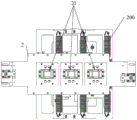
Fig. 1 is a schematic perspective view of the adaptive elastic jig of the present invention.
Fig. 2 is a schematic plane structure view of the adaptive elastic fixture in fig. 1 in a front view direction.
Fig. 3 is a schematic plan view of the adaptive elastic fixture in fig. 1.
Fig. 4 is a schematic perspective view of the lifting mechanism in the adaptive elastic fixture of the present invention.
Fig. 5 is a schematic perspective view of the loading plate and the elastic assembly in the adaptive elastic fixture of the present invention.
Fig. 6 is a schematic view of a three-dimensional structure of the loading plate and the elastic component after the workpiece is hidden in the adaptive elastic fixture of the present invention.
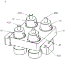
Fig. 7 is a schematic perspective view of an elastic assembly in the adaptive elastic fixture according to the present invention.
Fig. 8 is a schematic perspective view of an elastic element of an elastic assembly in the adaptive elastic fixture according to the present invention.
Detailed Description
In order to explain technical contents and structural features of the present invention in detail, the following description is made with reference to the embodiments and the accompanying drawings.
Referring to fig. 1 to 6, the present invention provides an adaptive elastic fixture 100, which includes a pressing mechanism 3, a pressing plate 2, a lifting mechanism 1, an elastic component 4 and a bearing plate 5 for positioning a workpiece 200, wherein the pressing plate 2 is located above the bearing plate 5, the pressing plate 2 is installed at an output end of the pressing mechanism 3, and the pressing plate 2 is driven by the pressing mechanism 3 to lift; the bearing plate 5 is arranged at the output end of the lifting mechanism 1, the bearing plate 5 is driven by the lifting mechanism 1 to lift, and the workpieces 200 can be pressed together by the mutual matching of the lower pressing plate 2 and the bearing plate 5, so that the purpose of positioning is achieved; the elastic component 4 is installed on the bearing plate 5, and the workpiece 200 can be elastically supported on the bearing plate 5 by virtue of the elastic expansion of the elastic component 4, so that the workpiece 200 can be elastically supported between the bearing plate 5 and the lower pressing plate 2, thereby preventing the lower pressing plate 2 and the bearing plate 5 from crushing the workpiece 200, and further improving the qualification rate of the workpiece 200. Additionally, the utility model discloses an not only the lift of holding down plate 2 of self-adaptation elastic jig 100 reaches the purpose that compresses tightly work piece 200 jointly with the lift of loading board 5, and the lift of loading board 5 can also realize nimble adjustment to the elastic force of elastic component 4 in addition, and when the elastic force was not enough, loading board 5 rose in order to reach the purpose of elastic force compensation, and when the elastic force was too big, loading board 5 descended in order to reduce the elastic force, had the purpose of adjusting in a flexible way. More specifically, the following:
referring to fig. 1, the pressing mechanism 3 includes a mounting plate 31 and a first lifting device 32 mounted on the mounting plate 31, the mounting plate 31 is used for being connected to an external machine to achieve a fixing purpose, the pressing plate 2 is mounted at an output end of the first lifting device 32, and the pressing plate 2 is driven by the first lifting device 32 to lift. The lower pressing mechanisms 3 are symmetrically connected to two sides of the lower pressing plate 2, so that the smoothness and stability of the lifting of the lower pressing plate 2 are improved. In this embodiment, two pressing mechanisms 3 are provided, and the two pressing mechanisms 3 are symmetrically disposed on two sides of the pressing plate 2. Preferably, the first lifting device 32 is a driving motor, but is not limited thereto.
Referring to fig. 1, a machining hole 21 for allowing laser to pass through is formed in the lower pressing plate 2, and the machining hole 21 is disposed such that the lower pressing plate 2 can press the workpiece 200 and simultaneously allow the laser to pass through the machining hole 21 to perform laser processing on the pressed workpiece 200. Preferably, all the machining holes 21 are provided at equal intervals in the longitudinal direction of the lower platen 2. In this embodiment, there are three laser stations, three corresponding machining holes 21 are provided, and all the machining holes 21 are provided at equal intervals along the length direction of the lower platen 2.
Referring to fig. 1 and 5 to 6, the lifting mechanism 1 includes a connection plate 11 and a second lifting device 12 installed on the connection plate 11, the connection plate 11 is used for connecting with an external machine to achieve a fixing purpose, the connection plate 11 is installed at an output end of the second lifting device 12, and the connection plate 11 is driven by the second lifting device 12 to lift. Specifically, the bearing plate 5 includes a bottom plate 51 and an installation seat 52 disposed on the bottom plate 51, positioning columns 53 for positioning the workpiece 200 are disposed on the bottom plate 51 and the installation seat 52, all the positioning columns 53 jointly form a clamping position clamped with the workpiece 200, an installation groove 521 is disposed on the installation seat 52 corresponding to the elastic component 4, and the elastic component 4 is disposed in the installation groove 521, so as to achieve the positioning purpose.
Referring to fig. 6 to 8, the elastic assembly 4 includes a fixing base 41 and an elastic element 42 embedded in the fixing base 41, and the fixing base 41 is mounted on the supporting plate 5. The elastic element 42 includes a fixed column 421, a supporting column 422 and an elastic element 423, the fixed column 421 is installed on the fixed seat 41, the fixed column 421 has a cavity 4211, the cavity 4211 is cylindrical, a communication hole 4212 is formed at the top end of the fixed column 421, the supporting column 422 is slidably disposed in the cavity 4211 and extends out of the cavity 4211 or retracts back through the communication hole 4212, and the elastic element is disposed between the cavity 4211 and the supporting column 422 so that the supporting column 422 has a tendency of extending out of the cavity 4211. Specifically, the supporting column 422 includes a sliding column 4221 and a limit edge 4222 formed by the sliding column 4221 extending outward, when the supporting column 422 extends out of the cavity 4211, the limit edge 4222 supports against the inner wall of the cavity 4211 for limiting, so as to avoid the supporting column 422 from falling out. Preferably, the elastic elements 42 are arranged in the fixing base 41 in a rectangular shape, so as to realize stable propping. In the present embodiment, the elastic elements 42 are arranged in groups of four, and three groups are arranged to correspond to three laser stations.
Referring to fig. 1 to 8, the working principle of the adaptive elastic fixture 100 of the present invention is further described as follows:
the workpiece 200 is placed on the bearing plate 5, the positioning column 53 of the bearing plate 5 positions the workpiece 200 together, the lower pressing plate 2 is driven by the lower pressing mechanism 3 to lift, the bearing plate 5 is driven by the lifting mechanism 1 to lift, the lower pressing plate 2 and the bearing plate 5 are matched with each other to compress the workpiece 200 together, the workpiece 200 can be elastically borne on the bearing plate 5 through elastic expansion and contraction of the elastic assembly 4, so that the workpiece 200 can be elastically pressed between the bearing plate 5 and the lower pressing plate 2, in the process, when the elastic force is insufficient, the bearing plate 5 is driven by the lifting mechanism 1 to lift to achieve the purpose of elastic force compensation, and when the elastic force is too large, the bearing plate 5 is driven by the lifting mechanism 1 to lower to reduce the elastic force.
The lower pressing plate 2 is positioned above the bearing plate 5 by combining the lower pressing mechanism 3, the lower pressing plate 2, the lifting mechanism 1, the elastic component 4, the bearing plate 5 for positioning the workpiece 200 and the like together, the lower pressing plate 2 is arranged at the output end of the lower pressing mechanism 3, and the lower pressing plate 2 is driven by the lower pressing mechanism 3 to lift; the bearing plate 5 is arranged at the output end of the lifting mechanism 1, the bearing plate 5 is driven by the lifting mechanism 1 to lift, and the lower pressing plate 2 and the bearing plate 5 are matched with each other to press the workpiece 200 together; the elastic component 4 is installed on the bearing plate 5, and the workpiece 200 can be elastically supported on the bearing plate 5 by virtue of the elastic expansion of the elastic component 4, so that the workpiece 200 can be elastically supported between the bearing plate 5 and the lower pressing plate 2, thereby preventing the lower pressing plate 2 and the bearing plate 5 from crushing the workpiece 200, and further improving the qualification rate of the workpiece 200. Additionally, the utility model discloses an not only the lift of holding down plate 2 and the lift of loading board 5 of self-adaptation elastic jig 100 reach the purpose that compresses tightly work piece 200 jointly, and the lift of loading board 5 can also realize nimble adjustment to the elastic force of elastic component 4 moreover, and when the elastic force was not enough, loading board 5 rose in order to reach the purpose of elastic force compensation, and when the elastic force was too big, loading board 5 descended in order to reduce the elastic force. Because the utility model discloses an adaptive elastic jig 100 still has advantages such as simple structure and location accuracy.
The above disclosure is only a preferred embodiment of the present invention, and the scope of the claims of the present invention should not be limited thereby, and all the equivalent changes made in the claims of the present invention are intended to be covered by the present invention.
Claims (10)
1. The utility model provides a self-adaptation elasticity tool which characterized in that: the device comprises a pressing mechanism, a pressing plate, a lifting mechanism, an elastic assembly and a bearing plate for positioning a workpiece, wherein the pressing plate is positioned above the bearing plate, the pressing plate is arranged at the output end of the pressing mechanism, and the pressing plate is driven by the pressing mechanism to lift; the bearing plate is arranged at the output end of the lifting mechanism and driven by the lifting mechanism to lift; the elastic component is arranged on the bearing plate, and the workpiece can be elastically borne on the bearing plate by means of elastic expansion of the elastic component.
2. The adaptive elastic jig according to claim 1, wherein the pressing mechanism comprises a mounting plate and a first lifting device mounted on the mounting plate, the pressing plate is mounted at an output end of the first lifting device, and the pressing plate is driven by the first lifting device to lift.
3. The adaptive elastic jig according to claim 1, wherein the pressing mechanisms are symmetrically connected to both sides of the lower pressing plate.
4. The adaptive elastic jig according to claim 1, wherein the lower press plate is provided with a processing hole for passing laser.
5. The adaptive elastic jig according to claim 1, wherein the lifting mechanism comprises a connecting plate and a second lifting device installed on the connecting plate, the connecting plate is installed at an output end of the second lifting device, and the connecting plate is driven by the second lifting device to lift.
6. The adaptive elastic jig according to claim 1, wherein the bearing plate comprises a bottom plate and a mounting seat arranged on the bottom plate, positioning columns for positioning a workpiece are arranged on the bottom plate and the mounting seat, a mounting groove is formed in the mounting seat corresponding to the elastic component, and the elastic component is arranged in the mounting groove.
7. The adaptive elastic fixture according to claim 1, wherein the elastic assembly comprises a fixing seat and an elastic element embedded in the fixing seat, and the fixing seat is mounted on the bearing plate.
8. The adaptive elastic fixture according to claim 7, wherein the elastic element comprises a fixed column, an abutting column and an elastic element, the fixed column is mounted on the fixed seat, the fixed column has a cavity, a communication hole is formed in the top end of the fixed column, the abutting column is slidably disposed in the cavity and extends out of or retracts into the cavity through the communication hole, and the elastic element is disposed between the cavity and the abutting column so that the abutting column always tends to extend out of the cavity.
9. The adaptive elastic jig according to claim 8, wherein the abutting columns comprise sliding columns and limiting edges formed by the sliding columns extending outwards, and when the abutting columns extend out of the cavity, the limiting edges abut against the inner wall of the cavity to limit the position.
10. The adaptive elastic fixture according to claim 7, wherein the elastic elements are arranged in the fixing seat in a rectangular shape.
Priority Applications (1)
| Application Number | Priority Date | Filing Date | Title |
|---|---|---|---|
| CN202021829453.2U CN213495396U (en) | 2020-08-27 | 2020-08-27 | Self-adaptive elastic jig |
Applications Claiming Priority (1)
| Application Number | Priority Date | Filing Date | Title |
|---|---|---|---|
| CN202021829453.2U CN213495396U (en) | 2020-08-27 | 2020-08-27 | Self-adaptive elastic jig |
Publications (1)
| Publication Number | Publication Date |
|---|---|
| CN213495396U true CN213495396U (en) | 2021-06-22 |
Family
ID=76442579
Family Applications (1)
| Application Number | Title | Priority Date | Filing Date |
|---|---|---|---|
| CN202021829453.2U Active CN213495396U (en) | 2020-08-27 | 2020-08-27 | Self-adaptive elastic jig |
Country Status (1)
| Country | Link |
|---|---|
| CN (1) | CN213495396U (en) |
-
2020
- 2020-08-27 CN CN202021829453.2U patent/CN213495396U/en active Active
Similar Documents
| Publication | Publication Date | Title |
|---|---|---|
| CN209869496U (en) | Clamp for fixing die | |
| CN104476272A (en) | Special fixture for clamping frame artifacts | |
| CN102699715B (en) | Clamping device | |
| CN213495396U (en) | Self-adaptive elastic jig | |
| CN213351648U (en) | Clamp for machining thin accessory of communication equipment | |
| CN202701823U (en) | Clamping device | |
| CN206084864U (en) | Assembly jig | |
| CN215357126U (en) | Press fitting device | |
| CN211101772U (en) | V-shaped groove machining device | |
| CN220347772U (en) | Pump cover shell clamp for vertical machining center | |
| CN216913460U (en) | Machine table clamp device | |
| CN219562012U (en) | Efficient welding positioning clamping fixture | |
| CN220560987U (en) | Clamp for machining ultra-deep groove workpiece | |
| CN218476049U (en) | Casing frock clamp | |
| CN211247948U (en) | Die holder for simultaneously punching double sides of automobile U-shaped support piece | |
| CN218284646U (en) | Pneumatic supporting structure and pneumatic supporting device | |
| CN220480972U (en) | Processing jig for plate-shaped metal piece | |
| CN219094907U (en) | Mounting fixture with raising and lowering functions | |
| CN214721872U (en) | Positioning fixture for welding fastening nut of tail gate rib plate | |
| CN216760851U (en) | Pressure maintaining jig | |
| CN212019549U (en) | Positioning jig and digit control machine tool | |
| CN219521349U (en) | Movable platen processing jig | |
| CN217595676U (en) | Flanging die | |
| CN210908887U (en) | Automatic screw driving machine | |
| CN220611946U (en) | Clamping device for lifting lug machining |
Legal Events
| Date | Code | Title | Description |
|---|---|---|---|
| GR01 | Patent grant | ||
| GR01 | Patent grant |