CN213491106U - Drip cup of infusion apparatus - Google Patents
Drip cup of infusion apparatus Download PDFInfo
- Publication number
- CN213491106U CN213491106U CN202021721071.8U CN202021721071U CN213491106U CN 213491106 U CN213491106 U CN 213491106U CN 202021721071 U CN202021721071 U CN 202021721071U CN 213491106 U CN213491106 U CN 213491106U
- Authority
- CN
- China
- Prior art keywords
- pipe
- toper
- kettle
- liquid feeding
- drip cup
- Prior art date
- Legal status (The legal status is an assumption and is not a legal conclusion. Google has not performed a legal analysis and makes no representation as to the accuracy of the status listed.)
- Active
Links
Images
Abstract
The utility model discloses a transfusion system kettle, including the kettle, connect the feed liquor pipe in the top of kettle, connect the drain pipe in the below of kettle the charge device is connected to top one side of kettle, and charge device includes the liquid feeding pipe, and the below of liquid feeding pipe is equipped with uncovered intercommunication the kettle connects the toper pipe in one side of liquid feeding pipe, and the great one end opening intercommunication of toper pipe the liquid feeding pipe sets up elastic sealing device in the toper intraductal, and elastic sealing device is used for the shutoff the less one end opening of toper pipe. The utility model has the advantages that: this device sets up the liquid feeding pipe through top one side at the kettle, can make things convenient for medical personnel to add the medicine, sets up the toper pipe in one side of liquid feeding pipe, sets up elastic sealing device in the toper pipe, not only can make the syringe disect insertion toper intraductal add the medicine, can also effectively seal the mouth of pipe of toper pipe, prevents that the air from getting into in the kettle.
Description
Technical Field
The utility model relates to the technical field of medical equipment, especially, relate to a kettle is dripped to transfusion system.
Background
An infusion set, a very common medical device, establishes a path between a vein and a medical fluid for intravenous infusion. Some medications are administered via a drip chamber during the treatment of the patient to achieve the best treatment with the least adverse consequences to the patient, especially during surgery, which is often required. This type of administration requires the medical care personnel to use the syringe needle to directly puncture the medication channel beside the drip cup, which often causes the syringe needle to prick the operator himself, especially a new person who has just participated in the work. Thus, not only are the health care workers themselves injured, but contamination of the medication may also occur, and in addition, the possibility of transmission of some infectious diseases between the health care workers and the patient is increased.
SUMMERY OF THE UTILITY MODEL
The utility model aims to solve the defects in the prior art and provides a drip cup of an infusion apparatus.
In order to achieve the above purpose, the utility model adopts the following technical scheme:
the utility model provides a kettle drips transfusion system, includes the kettle that drips, connects the feed liquor pipe in the top of kettle, connects the drain pipe in the below of kettle drip the charge device is connected to top one side of kettle, and charge device includes the liquid feeding pipe, and the below of liquid feeding pipe is equipped with uncovered intercommunication the kettle that drips connects the conical tube in one side of liquid feeding pipe, the great one end opening intercommunication of conical tube the liquid feeding pipe sets up elastic sealing device in the conical tube, and elastic sealing device is used for the shutoff the less one end opening of conical tube.
Preferably, the elastic sealing device comprises two fixing plates, the two fixing plates are respectively vertically connected to two opposite side walls in the conical tube, a through hole is formed in each fixing plate, a sliding rod is inserted into each through hole in a sliding mode, one end, facing the smaller opening of the conical tube, of each sliding rod is connected with a connecting plate, an insertion column is connected to the end portion of each connecting plate, and the two insertion columns are used for plugging the smaller end opening of the conical tube.
Preferably, each connecting plate is horizontally parallel to the adjacent side wall in the conical tube, and an included angle between each connecting plate and the corresponding inserting column is degree.
Preferably, each sliding rod is sleeved with a spring, one end of each spring is connected to one side of the fixed plate, and the other end of each spring is connected to one side of the connecting plate.
Preferably, an oval sphere is connected to an outlet at the lower part of the liquid inlet pipe, a cavity is arranged in the sphere and communicated with the liquid inlet pipe, an opening is arranged below the cavity, and a floating ball is arranged in the cavity.
Preferably, a vertical bar is connected below the floating ball, the vertical bar penetrates through the opening downwards, a transverse bar is connected below the vertical bar, two ends of the transverse bar are both connected with the floating plate, a piston block is connected below the middle of the transverse bar, the piston block is used for plugging the opening of the liquid outlet pipe, and the lower end of the piston block is conical.
The utility model has the advantages that: the utility model provides a transfusion system drip cup sets up the liquid feeding pipe through top one side at the drip cup, can make things convenient for medical personnel to add the medicine, sets up the toper pipe in one side of liquid feeding pipe, sets up elastic sealing device in the toper is intraductal, not only can make the syringe disect insertion toper intraductal add the medicine, can also effectively seal the mouth of pipe of toper pipe, prevents that the air from getting into in the drip cup.
Drawings
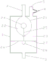
Fig. 1 is a schematic structural view of a drip cup of an infusion apparatus provided by the present invention;
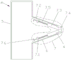
fig. 2 is a schematic view of the structure of the drug adding device.
Detailed Description
In order to make the objects, technical solutions and advantages of the present invention more clearly understood, the present invention is further described in detail below with reference to the accompanying drawings and embodiments. It should be understood that the specific embodiments described herein are merely illustrative of the invention and are not intended to limit the invention.
As shown in fig. 1, the utility model provides a drip cup of infusion apparatus, which comprises a drip cup 1, a liquid inlet pipe 2 is connected above the drip cup 1, a liquid outlet pipe 3 is connected below the drip cup 1, an oval sphere 2.1 is connected at the lower outlet of the liquid inlet pipe 2, a cavity 2.2 is arranged in the sphere 2.1, the cavity 2.2 is communicated with the liquid inlet pipe 2, an opening 2.3 is arranged below the cavity 2.2, a floating ball 2.4 is arranged in the cavity 2.2, the density of the floating ball 2.4 is less than that of the liquid medicine, so that the floating ball 2.4 can float above the liquid medicine, the diameter of the floating ball 2.4 is more than that of the opening 2.3, the floating ball 2.4 can block the opening 2.3, the liquid medicine in the infusion bottle enters the cavity 2.2 along the liquid inlet pipe 2, the liquid medicine fills the cavity 2.2, the floating ball 2.4 floats on the liquid medicine, when the liquid medicine in the cavity 2.2.2 completely enters the drip cup 1, the liquid medicine moves downwards along the drip cup 2.4 to, the liquid medicine in the liquid outlet pipe 3 is static, and air is prevented from entering the human body.
However, when the floating ball 2.4 blocks the opening 2.3, a part of liquid medicine is still left in the drip cup 1 at this time, which causes waste, so the vertical bar 2.5 is connected below the floating ball 2.4, the vertical bar 2.5 passes through the opening 2.3 downwards, the horizontal bar 2.6 is connected below the vertical bar 2.5, the floating plates 2.7 are connected at both ends of the horizontal bar 2.6, the density of the floating plates 2.7 is less than that of the liquid medicine, the piston block 2.8 is connected below the middle of the horizontal bar 2.7, the diameter of the piston block 2.8 is equal to the inner diameter of the liquid outlet pipe 3, the piston block 2.8 is used for blocking the liquid outlet pipe 3, and the lower end of the piston block 2.8 is in a pointed cone shape, which can be inserted into the liquid outlet pipe 3 more conveniently.
When all the liquid medicine in the drip cup 1 enters the liquid outlet pipe 3, the floating plate 2.7 descends to drive the piston block 2.8 to descend, and the piston block 2.8 is inserted into the pipe orifice of the liquid outlet pipe 3, so that the liquid outlet pipe 3 is blocked, the liquid medicine in the liquid inlet pipe stops flowing, and air is prevented from entering the blood vessel after the liquid medicine is completely infused.
Elastic sealing device 7 includes two fixed plates 7.1, and two fixed plates 7.1 are connected perpendicularly respectively on the relative both sides wall in the conical tube 6, all be equipped with the through-hole on every fixed plate 7.1, at every through-hole in equal slip grafting slide bar 7.2, at every slide bar 7.2 orientation connecting plate 7.3 is all connected to the less open-ended one end of conical tube 6, all connects limiting plate 7.6 at every slide bar 7.2's the other end, all cup joints spring 7.5 on every slide bar 7.2, and one side at fixed plate 7.1 is all connected to the one end of every spring 7.5, and one side at connecting plate 7.3 is all connected to every spring 7.5's the other end.
Each connecting plate 7.3 is horizontally parallel to the adjacent side wall in the conical tube 6, an inserting column 7.4 is connected to the end of each connecting plate 7.3, the included angle between each connecting plate 7.3 and the corresponding inserting column 7.4 is 150 degrees, and the two inserting columns 7.3 are used for inserting and plugging the smaller end opening of the conical tube 6.
When medical personnel add medicine in to drip cup 1, insert in the less one end mouth of pipe of conical duct 6 through the front end osculum of syringe, thereby promote two peg graft post 7.3, make two peg graft post 7.3 to conical duct 6 inboard one side, thereby make two peg graft post 7.3 break away from the less mouth of pipe of conical duct 6, make the front end osculum of syringe enter into conical duct 6 in, then inject the liquid medicine into conical duct 6, then the liquid medicine carries out in the filling tube 5 along conical duct 6's inside wall, enter into drip cup 1 at last, then make and take out the syringe, make two peg graft post 7.3 seal the less one end mouth of pipe of conical duct 6 under spring 7.5's effect, can effectively prevent that the air from entering into in the drip cup.
Claims (6)
1. The utility model provides a kettle is dripped to transfusion system, includes and drips kettle (1), connects feed liquor pipe (2) in the top of dripping kettle (1), connects drain pipe (3) in the below of dripping kettle (1), its characterized in that: medicine adding device (4) is connected to top one side of drip cup (1), and medicine adding device (4) includes liquid feeding pipe (5), and the below of liquid feeding pipe (5) is equipped with uncovered intercommunication drip cup (1), connects toper pipe (6) in one side of liquid feeding pipe (5), and the great one end opening of toper pipe (6) communicates liquid feeding pipe (5) set up elastic sealing device (7) in toper pipe (6), and elastic sealing device (7) are used for the shutoff less one end opening of toper pipe (6).
2. The infusion set drip cup according to claim 1, wherein: elastic sealing device (7) include two fixed plates (7.1), and two fixed plates (7.1) are connected perpendicularly respectively on the relative both sides wall in toper pipe (6), all are equipped with the through-hole on every fixed plate (7.1), at equal slip grafting slide bar (7.2) in every through-hole, at every slide bar (7.2) orientation connecting plate (7.3) are all connected to the less open-ended one end of toper pipe (6), limiting plate (7.6) are all connected to the other end at every slide bar (7.2), peg graft post (7.4) are all connected to the tip at every connecting plate (7.3), and two peg graft posts (7.3) are used for pegging graft the shutoff the less one end opening of toper pipe (6).
3. The infusion set drip chamber of claim 2, wherein: each connecting plate (7.3) is horizontally parallel to the adjacent side wall in the conical tube (6), and the included angle between each connecting plate (7.3) and the corresponding inserting column (7.4) is 150 degrees.
4. The infusion set drip chamber of claim 2, wherein: each sliding rod (7.2) is sleeved with a spring (7.5), one end of each spring (7.5) is connected to one side of the fixed plate (7.1), and the other end of each spring (7.5) is connected to one side of the connecting plate (7.3).
5. The infusion set drip cup according to claim 1, wherein: an oval sphere (2.1) is connected to an outlet at the lower part of the liquid inlet pipe (2), a cavity (2.2) is arranged in the sphere (2.1), the cavity (2.2) is communicated with the liquid inlet pipe (2), an opening (2.3) is arranged below the cavity (2.2), and a floating ball (2.4) is arranged in the cavity (2.2).
6. The infusion set drip cup according to claim 5, wherein: the lower extreme of floater (2.4) is connected vertical bar (2.5), and vertical bar (2.5) pass downwards opening (2.3), connect horizontal bar (2.6) in the below of vertical bar (2.5), all connect kickboard (2.7) at the both ends of horizontal bar (2.6), connect piston block (2.8) in the centre below of horizontal bar (2.7), and piston block (2.8) are used for the shutoff drain pipe (3), and the lower extreme of piston block (2.8) is the taper.
Priority Applications (1)
| Application Number | Priority Date | Filing Date | Title |
|---|---|---|---|
| CN202021721071.8U CN213491106U (en) | 2020-08-18 | 2020-08-18 | Drip cup of infusion apparatus |
Applications Claiming Priority (1)
| Application Number | Priority Date | Filing Date | Title |
|---|---|---|---|
| CN202021721071.8U CN213491106U (en) | 2020-08-18 | 2020-08-18 | Drip cup of infusion apparatus |
Publications (1)
| Publication Number | Publication Date |
|---|---|
| CN213491106U true CN213491106U (en) | 2021-06-22 |
Family
ID=76440400
Family Applications (1)
| Application Number | Title | Priority Date | Filing Date |
|---|---|---|---|
| CN202021721071.8U Active CN213491106U (en) | 2020-08-18 | 2020-08-18 | Drip cup of infusion apparatus |
Country Status (1)
| Country | Link |
|---|---|
| CN (1) | CN213491106U (en) |
-
2020
- 2020-08-18 CN CN202021721071.8U patent/CN213491106U/en active Active
Similar Documents
| Publication | Publication Date | Title |
|---|---|---|
| US3332418A (en) | Injection site for venoclysis apparatus | |
| EP2496288B1 (en) | Double-lumen spike connector with a gas-blocking element for a hemodialysis tube set | |
| WO2023138704A1 (en) | Automatic liquid-stop and blood-return-prevention infusion set | |
| CN109620721A (en) | A kind of sterile automatic medicine dispensing device and its application method | |
| CN213491106U (en) | Drip cup of infusion apparatus | |
| NO172277B (en) | SHELTER INTENDED FOR INSERT INTO AN INTRAVENOST DELIVERY EQUIPMENT | |
| US20190351130A1 (en) | Thorough-dripping medical infusion apparatus with infusion bottle having inbuilt balloon | |
| CN203970912U (en) | Disposable totally-enclosed suction, injection connector makes up a prescription | |
| CN211096608U (en) | Dropping funnel and siphon intravenous injection device | |
| CN208678058U (en) | One kind stopping liquid type bag transfusion system | |
| CN208492831U (en) | Automatic exhaust, only liquid, accurate filter device | |
| CN216061505U (en) | Medicine adding piece for infusion apparatus | |
| CN209475276U (en) | A kind of infusion apparatus | |
| CN201042544Y (en) | Device for powder preparation medicament dissolution and transfusion | |
| CN203954198U (en) | Disposable totally-enclosed suction medicine injection connector | |
| CN215653039U (en) | Novel normal saline tube sealing liquid device | |
| CN213031512U (en) | Disposable transfusion system | |
| CN204864015U (en) | Liquid syringe is joined in marriage to filtration formula | |
| CN215274995U (en) | Infusion apparatus capable of preventing air embolism | |
| CN208943076U (en) | A kind of double passage transfusion device | |
| CN216963177U (en) | Anti-backflow venous infusion apparatus | |
| CN219110407U (en) | Precise filtering transfusion device capable of needleless dosing | |
| CN210991908U (en) | Enteral nutrition injector | |
| CN215133417U (en) | Safe type liquid distribution infusion bag | |
| CN216536389U (en) | Anti-backflow infusion apparatus |
Legal Events
| Date | Code | Title | Description |
|---|---|---|---|
| GR01 | Patent grant | ||
| GR01 | Patent grant |