CN213486173U - Irrigation device for hydraulic engineering - Google Patents
Irrigation device for hydraulic engineering Download PDFInfo
- Publication number
- CN213486173U CN213486173U CN202022337272.4U CN202022337272U CN213486173U CN 213486173 U CN213486173 U CN 213486173U CN 202022337272 U CN202022337272 U CN 202022337272U CN 213486173 U CN213486173 U CN 213486173U
- Authority
- CN
- China
- Prior art keywords
- fixedly connected
- filter screen
- box
- irrigation device
- filter box
- Prior art date
- Legal status (The legal status is an assumption and is not a legal conclusion. Google has not performed a legal analysis and makes no representation as to the accuracy of the status listed.)
- Active
Links
Images
Classifications
-
- Y—GENERAL TAGGING OF NEW TECHNOLOGICAL DEVELOPMENTS; GENERAL TAGGING OF CROSS-SECTIONAL TECHNOLOGIES SPANNING OVER SEVERAL SECTIONS OF THE IPC; TECHNICAL SUBJECTS COVERED BY FORMER USPC CROSS-REFERENCE ART COLLECTIONS [XRACs] AND DIGESTS
- Y02—TECHNOLOGIES OR APPLICATIONS FOR MITIGATION OR ADAPTATION AGAINST CLIMATE CHANGE
- Y02P—CLIMATE CHANGE MITIGATION TECHNOLOGIES IN THE PRODUCTION OR PROCESSING OF GOODS
- Y02P60/00—Technologies relating to agriculture, livestock or agroalimentary industries
- Y02P60/12—Technologies relating to agriculture, livestock or agroalimentary industries using renewable energies, e.g. solar water pumping
Landscapes
- Filtration Of Liquid (AREA)
Abstract
The utility model discloses a irrigation device for hydraulic engineering relates to irrigation equipment field, including the rose box, the one end of the inner chamber of rose box is provided with the filter screen, the week side of filter screen and the inner chamber wall fixed connection of rose box, one side of filter screen is provided with the clamp plate, a terminal surface fixedly connected with brush of clamp plate, the brush is connected with a side laminating of filter screen, the up end fixedly connected with movable rod of clamp plate, the upper end inner wall of rose box is run through to the upper end of movable rod and extends to the top of rose box. The utility model discloses a fixedly connected with runner and flabellum respectively at the both ends of loose axle, one side of runner has the connecting rod through connecting axle swing joint, and the connecting rod is through round pin axle and loose rod swing joint, and the flabellum rotates under the wind-force effect, and then drives the brush and can scrub the side of filter screen, avoids the filter screen to be blockked up, and this device uses wind-force as power, the more energy can be saved during the use.
Description
Technical Field
The utility model relates to a irrigation equipment field, in particular to irrigation device for hydraulic engineering.
Background
Nowadays, the economy of China realizes high-speed development, various supporting facilities are improved, hydraulic engineering is the key point of basic engineering construction of China, and the development of the national economy of China is inseparable and has important influence on the life of people. To improve the function of hydraulic engineering, the quality of hydraulic engineering needs to be improved continuously. On the basis to hydraulic engineering irrigation construction technical research, quality that can progressively promote hydraulic engineering irrigation, it can ensure hydraulic engineering irrigation's quality. At present, current irrigation device for hydraulic engineering, its filter screen uses easily by debris jam for a long time to waste time and energy when the filter screen clearance.
Therefore, it is necessary to provide a water conservancy irrigation device for water conservancy projects to solve the above problems.
SUMMERY OF THE UTILITY MODEL
An object of the utility model is to provide a irrigation device for hydraulic engineering to solve the problem that proposes in the above-mentioned background art.
In order to achieve the above object, the utility model provides a following technical scheme: a water conservancy irrigation device for hydraulic engineering comprises a filter box, wherein a filter screen is arranged at one end of an inner cavity of the filter box, the periphery of the filter screen is fixedly connected with the inner cavity wall of the filter box, a pressing plate is arranged at one side of the filter screen, a brush is fixedly connected with one end face of the pressing plate and is connected with one side face of the filter screen in a laminating manner, a movable rod is fixedly connected with the upper end face of the pressing plate, the upper end of the movable rod penetrates through the inner wall of the upper end of the filter box and extends to the upper part of the filter box, a rotating wheel is arranged at one side of the upper end of the movable rod, a connecting shaft is movably inserted into the edge of one side face of the rotating wheel through a bearing, a connecting rod is fixedly connected with one end of the connecting shaft, the lower end of the connecting rod is movably connected with the upper end of the, one end of the movable shaft is fixedly connected with the middle part of the rotating wheel in an inserting mode, and the other end of the movable shaft is fixedly connected with a fan blade.
Preferably, the two end faces of the filter box are communicated with connecting pipes, and the inner wall of the other end of the filter box is connected with a baffle in an attaching mode.
Preferably, the upper end of the baffle is movably connected with the upper end of the inner wall of the other end of the filter box through a pin shaft, and the upper end of the baffle is fixedly connected with a limiting rod.
Preferably, the lower surface of the filter box is fixedly connected with a collecting box, the collecting box is communicated with the inner cavity of the filter box, and the collecting box is located under the pressing plate.
Preferably, the opening has been seted up to the lower extreme inner wall of collecting box, the lower surface laminating of collecting box is connected with the closing plate.
Preferably, the two sides of the sealing plate are clamped with clamping blocks, and the clamping blocks are fixedly connected with the lower surface of the collecting box.
Preferably, one end of the sealing plate is connected with a positioning bolt in an inserting mode through threads, and a plurality of lightening holes distributed in an annular array mode are formed in one side face of the rotating wheel.
The utility model discloses a technological effect and advantage:
1. the utility model discloses a both ends at the loose axle respectively fixedly connected with runner and flabellum, one side of runner has the connecting rod through connecting axle swing joint, the connecting rod is through round pin axle and loose rod swing joint, the flabellum rotates under the wind-force effect, and then drives the loose rod and slide in vertical direction, thereby make the brush can scrub the side of filter screen, avoid the filter screen to be blockked up, this device uses wind-force as power, the more energy can be saved during the use, and need not manual operation, therefore labour saving and time saving more;
2. the utility model discloses an it is connected with the baffle to laminate at the other end inner wall of rose box, the upper end of baffle is through the other end inner wall swing joint of round pin axle with the rose box, the lower extreme intercommunication of rose box has the collecting box, when this device irrigates, the baffle is opened automatically under the water impact, when stopping irrigating, the baffle self-closing under the action of gravity leaves the inner chamber of rose box with debris, and the clamp plate can impel the inner chamber of collecting box and collect with debris, consequently this device can effectively avoid debris to flow back to in the water tank (not drawn in the picture).
Drawings
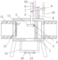
Fig. 1 is a schematic view of the overall structure section of the present invention.
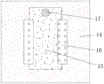
Fig. 2 is a schematic bottom view of the sealing plate structure of the present invention.
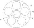
Fig. 3 is a schematic side view of the runner structure of the present invention.
In the figure: 1. a filter box; 2. a filter screen; 3. pressing a plate; 4. a brush; 5. a movable rod; 6. a rotating wheel; 61. a connecting shaft; 62. lightening holes; 7. a connecting rod; 8. a fixed mount; 9. a movable shaft; 10. a fan blade; 11. a connecting pipe; 12. a baffle plate; 13. a limiting rod; 14. a collection box; 15. a sealing plate; 16. a clamping block; 17. and (6) positioning the bolt.
Detailed Description
The technical solutions in the embodiments of the present invention will be described clearly and completely with reference to the accompanying drawings in the embodiments of the present invention, and it is obvious that the described embodiments are only some embodiments of the present invention, not all embodiments. Based on the embodiments in the present invention, all other embodiments obtained by a person skilled in the art without creative work belong to the protection scope of the present invention.
The utility model provides a water conservancy irrigation device for water conservancy project as shown in figures 1-3, as shown in figure 1, the irrigation device comprises a filter box 1, one end of the inner cavity of the filter box 1 is provided with a filter screen 2, the peripheral side of the filter screen 2 is fixedly connected with the inner cavity wall of the filter box 1, the filter screen 2 is used for filtering sundries in water, one side of the filter screen 2 is provided with a press plate 3, one end surface of the press plate 3 is fixedly connected with a brush 4, the brush 4 is connected with one side surface of the filter screen 2 in a fitting manner, the press plate 3 can drive the brush 4 to clean the side surface of the filter screen 2 when moving up and down in the vertical direction, thereby avoiding the filter screen 2 from being blocked due to excessive adhered sundries, the upper end surface of the press plate 3 is fixedly connected with a movable rod 5, the upper end of the movable rod 5 penetrates through the upper end inner wall of the filter box 1 and extends, the outer side wall of the movable rod 5 is connected with a sealing gasket in an adhering manner to improve the sealing performance between the movable rod 5 and the filter box 1, one side of the upper end of the movable rod 5 is provided with a rotating wheel 6, the edge of one side surface of the rotating wheel 6 is movably inserted with a connecting shaft 61 through a bearing, one end of the connecting shaft 61 is fixedly connected with a connecting rod 7, the lower end of the connecting rod 7 is movably connected with the upper end of the movable rod 5 through a pin shaft, a crank connecting rod mechanism is formed between the rotating wheel 6 and the connecting shaft 61 and the connecting rod 7, therefore, the rotating wheel 6 can drive the movable rod 5 to slide up and down in the vertical direction, one end of the upper surface of the filter box 1 is fixedly connected with a fixed frame 8, the upper end of the fixed frame 8 is connected with a movable shaft 9 in a penetrating manner, one end of the movable shaft 9 is fixedly inserted with, therefore this device uses wind-force as power, more energy can be saved, the both ends face of rose box 1 all communicates there is connecting pipe 11, connecting pipe 11 is used for being connected with water conservancy pipeline, the laminating of the other end inner wall of rose box 1 is connected with baffle 12, the upper end of baffle 12 is through the upper end swing joint of the other end inner wall of round pin axle and rose box 1, baffle 12 can rotate, the upper end fixedly connected with gag lever post 13 of baffle 12, gag lever post 13 can carry out spacingly to the rotation of baffle 12, when the water pump (not drawn in the picture) is drawn water, rivers impact baffle 12 and open baffle 12, filter screen 2 filters the debris in the aquatic, when stopping drawing water, baffle 12 closes under the action of gravity, thereby make debris can stop in the inner chamber of rose box 1.
As shown in fig. 2, a collecting box 14 is fixedly connected to the lower surface of the filter box 1, the collecting box 14 is communicated with the inner cavity of the filter box 1, the collecting box 14 is used for collecting sundries, the collecting box 14 is positioned right below the pressing plate 3, therefore, when the pressing plate 3 moves up and down in the vertical direction, the pressing plate 3 extrudes sundries in the inner cavity of the filter box 1, thereby extruding the sundries into the inner cavity of the collecting box 14, the inner wall of the lower end of the collecting box 14 is provided with an opening, the lower surface of the collecting box 14 is connected with a sealing plate 15 in a fitting way, the two sides of the sealing plate 15 are both clamped with clamping blocks 16, the clamping blocks 16 are fixedly connected with the lower surface of the collecting box 14, therefore, the opening of the lower end of the collecting box 14 can be opened by sliding the sealing plate 15, thereby be convenient for discharge the debris in the collecting box 14, the one end of sealing plate 15 has positioning bolt 17 through threaded plug connection, and positioning bolt 17's setting can be fixed sealing plate 15.
As shown in fig. 3, a plurality of lightening holes 62 distributed in an annular array are formed in one side surface of the runner 6, and the arrangement of the lightening holes 62 can reduce the overall weight of the runner 6 and prevent the runner 6 from blocking the flow of air.
The utility model discloses the theory of operation:
when the device is used, a water pump (not shown in the figure) is started, the water flow impacts the baffle 12 to open the baffle 12, the filter screen 2 filters sundries in water, and when the water pump (not shown in the figure) is closed, the baffle 12 rotates to be vertically placed under the action of gravity, so that the sundries can stay in an inner cavity of the filter box 1;
when external wind blows, the fan blades 10 are driven to rotate by wind power, the rotating wheel 6 is driven to rotate, the rotating wheel 6 drives the pressing plate 3 to move up and down in the vertical direction through the connecting action of the connecting shaft 61, the connecting rod 7 and the movable rod 5, and the brush 4 can brush the side face of the filter screen 2, so that the blockage caused by excessive sundries adhered to the surface of the filter screen 2 is avoided, and the pressing plate 3 can extrude sundries in the inner cavity of the filter box 1 when moving downwards, so that the sundries in the inner cavity of the filter box 1 are extruded into the inner cavity of the collecting box 14;
when the sundries are collected too much in the collecting box 14, the opening at the lower end of the collecting box 14 can be opened by sliding the sealing plate 15, thereby facilitating the discharge of the sundries in the inner cavity of the collecting box 14.
Finally, it should be noted that: although the present invention has been described in detail with reference to the foregoing embodiments, it will be apparent to those skilled in the art that modifications and variations can be made in the embodiments or in part of the technical features of the embodiments without departing from the spirit and the scope of the invention.
Claims (7)
1. The utility model provides a irrigation device for hydraulic engineering, includes rose box (1), its characterized in that: the filter box is characterized in that a filter screen (2) is arranged at one end of an inner cavity of the filter box (1), the periphery of the filter screen (2) is fixedly connected with the inner cavity wall of the filter box (1), a pressing plate (3) is arranged at one side of the filter screen (2), a brush (4) is fixedly connected with one end face of the pressing plate (3), the brush (4) is attached to one side face of the filter screen (2), a movable rod (5) is fixedly connected with the upper end face of the pressing plate (3), the upper end of the movable rod (5) penetrates through the inner wall of the upper end of the filter box (1) and extends to the upper side of the filter box (1), a rotating wheel (6) is arranged at one side of the upper end of the movable rod (5), a connecting shaft (61) is movably inserted into the edge of one side face of the rotating wheel (6) through a bearing, a connecting rod (7) is fixedly connected with one end of the connecting shaft (61, the one end fixedly connected with mount (8) of the upper surface of rose box (1), the upper end through connection of mount (8) has loose axle (9), the fixed grafting in middle part of the one end of loose axle (9) and runner (6), the other end fixedly connected with flabellum (10) of loose axle (9).
2. The irrigation device as claimed in claim 1, wherein: the two end faces of the filter box (1) are communicated with connecting pipes (11), and the inner wall of the other end of the filter box (1) is attached and connected with a baffle (12).
3. The irrigation device as claimed in claim 2, wherein: the upper end of the baffle (12) is movably connected with the upper end of the inner wall of the other end of the filter box (1) through a pin shaft, and the upper end of the baffle (12) is fixedly connected with a limiting rod (13).
4. The irrigation device as claimed in claim 3, wherein: the lower surface of the filter box (1) is fixedly connected with a collecting box (14), the collecting box (14) is communicated with the inner cavity of the filter box (1), and the collecting box (14) is located under the pressing plate (3).
5. The irrigation device as claimed in claim 4, wherein: an opening is formed in the inner wall of the lower end of the collecting box (14), and a sealing plate (15) is attached to the lower surface of the collecting box (14).
6. The irrigation device as claimed in claim 5, wherein: clamping blocks (16) are clamped on two sides of the sealing plate (15), and the clamping blocks (16) are fixedly connected with the lower surface of the collecting box (14).
7. The irrigation device as claimed in claim 6, wherein: one end of the sealing plate (15) is connected with a positioning bolt (17) in an inserting mode through threads, and a plurality of lightening holes (62) distributed in an annular array mode are formed in one side face of the rotating wheel (6).
Priority Applications (1)
| Application Number | Priority Date | Filing Date | Title |
|---|---|---|---|
| CN202022337272.4U CN213486173U (en) | 2020-10-20 | 2020-10-20 | Irrigation device for hydraulic engineering |
Applications Claiming Priority (1)
| Application Number | Priority Date | Filing Date | Title |
|---|---|---|---|
| CN202022337272.4U CN213486173U (en) | 2020-10-20 | 2020-10-20 | Irrigation device for hydraulic engineering |
Publications (1)
| Publication Number | Publication Date |
|---|---|
| CN213486173U true CN213486173U (en) | 2021-06-22 |
Family
ID=76400346
Family Applications (1)
| Application Number | Title | Priority Date | Filing Date |
|---|---|---|---|
| CN202022337272.4U Active CN213486173U (en) | 2020-10-20 | 2020-10-20 | Irrigation device for hydraulic engineering |
Country Status (1)
| Country | Link |
|---|---|
| CN (1) | CN213486173U (en) |
Cited By (3)
| Publication number | Priority date | Publication date | Assignee | Title |
|---|---|---|---|---|
| CN113856299A (en) * | 2021-11-08 | 2021-12-31 | 宁夏大学 | Filter equipment who strikes off structure with possessing intermittent type formula based on yellow river water is irrigated |
| CN114097576A (en) * | 2021-11-24 | 2022-03-01 | 徐州市贾汪区好莓农业科技有限公司 | Irrigation equipment for agricultural machine |
| CN116100479A (en) * | 2022-12-29 | 2023-05-12 | 无锡承拓机械科技有限公司 | High-heat-dissipation diamond grinding wheel |
-
2020
- 2020-10-20 CN CN202022337272.4U patent/CN213486173U/en active Active
Cited By (4)
| Publication number | Priority date | Publication date | Assignee | Title |
|---|---|---|---|---|
| CN113856299A (en) * | 2021-11-08 | 2021-12-31 | 宁夏大学 | Filter equipment who strikes off structure with possessing intermittent type formula based on yellow river water is irrigated |
| CN114097576A (en) * | 2021-11-24 | 2022-03-01 | 徐州市贾汪区好莓农业科技有限公司 | Irrigation equipment for agricultural machine |
| CN116100479A (en) * | 2022-12-29 | 2023-05-12 | 无锡承拓机械科技有限公司 | High-heat-dissipation diamond grinding wheel |
| CN116100479B (en) * | 2022-12-29 | 2023-11-07 | 无锡承拓机械科技有限公司 | High-heat-dissipation diamond grinding wheel |
Similar Documents
| Publication | Publication Date | Title |
|---|---|---|
| CN213486173U (en) | Irrigation device for hydraulic engineering | |
| CN111042081A (en) | Water resource garbage cleaning device | |
| CN218814208U (en) | Drainage diverging device for water supply and drainage engineering | |
| CN215977180U (en) | Water conservancy water and electricity dam water inlet floater cleaning device | |
| CN211158760U (en) | Domestic sewage treatment anti-clogging device | |
| CN115573310A (en) | Water retaining dam special for hydraulic and hydroelectric engineering | |
| CN212294564U (en) | Hydraulic engineering is with novel river sluice | |
| CN213328962U (en) | Water surface garbage treatment device for hydraulic engineering | |
| CN213448760U (en) | Foundation is handled with preventing blockking up sewage collecting pipe | |
| CN111749215B (en) | Lake surface floating green alga automatic collection device for constructed wetland | |
| CN209865471U (en) | Efficient condensate water recycling and filtering device | |
| CN210786431U (en) | Convenient fixed sewage purification device for environmental protection | |
| CN221589800U (en) | Auxiliary anti-blocking structure of water supply and drainage pipeline | |
| CN220878016U (en) | Grid machine for sewage treatment | |
| CN221422207U (en) | Pump station rubbish fishing device | |
| CN219863226U (en) | Road drainage device for preventing sponge city from being blocked | |
| CN213773201U (en) | Hydraulic pressure dam with surface of water pollutant collects mechanism | |
| CN217710589U (en) | Flashboard for hydraulic and hydroelectric engineering construction | |
| CN220433795U (en) | Rainwater collector | |
| CN215801432U (en) | Power station dam ecological flow hole trash device | |
| CN218188432U (en) | Rural domestic sewage treatment management device | |
| CN218911682U (en) | Waterproof drainage device | |
| CN221181834U (en) | Full-automatic impurity-removing automatic slag-discharging filter | |
| CN219151028U (en) | Flood drainage device for engineering management | |
| CN220813755U (en) | Branch salvaging equipment for hydraulic engineering |
Legal Events
| Date | Code | Title | Description |
|---|---|---|---|
| GR01 | Patent grant | ||
| GR01 | Patent grant |